2
Table of contents
01 General information................................................. 3
01.01 Safety......................................................................3
01.02 Warranty and liability ...............................................3
01.03 Disposal...................................................................3
02 Product description ................................................ 3
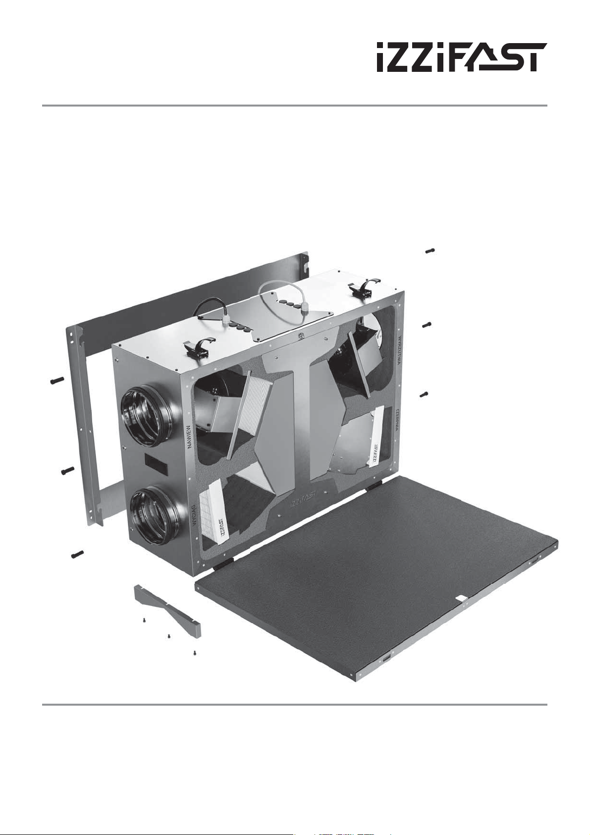
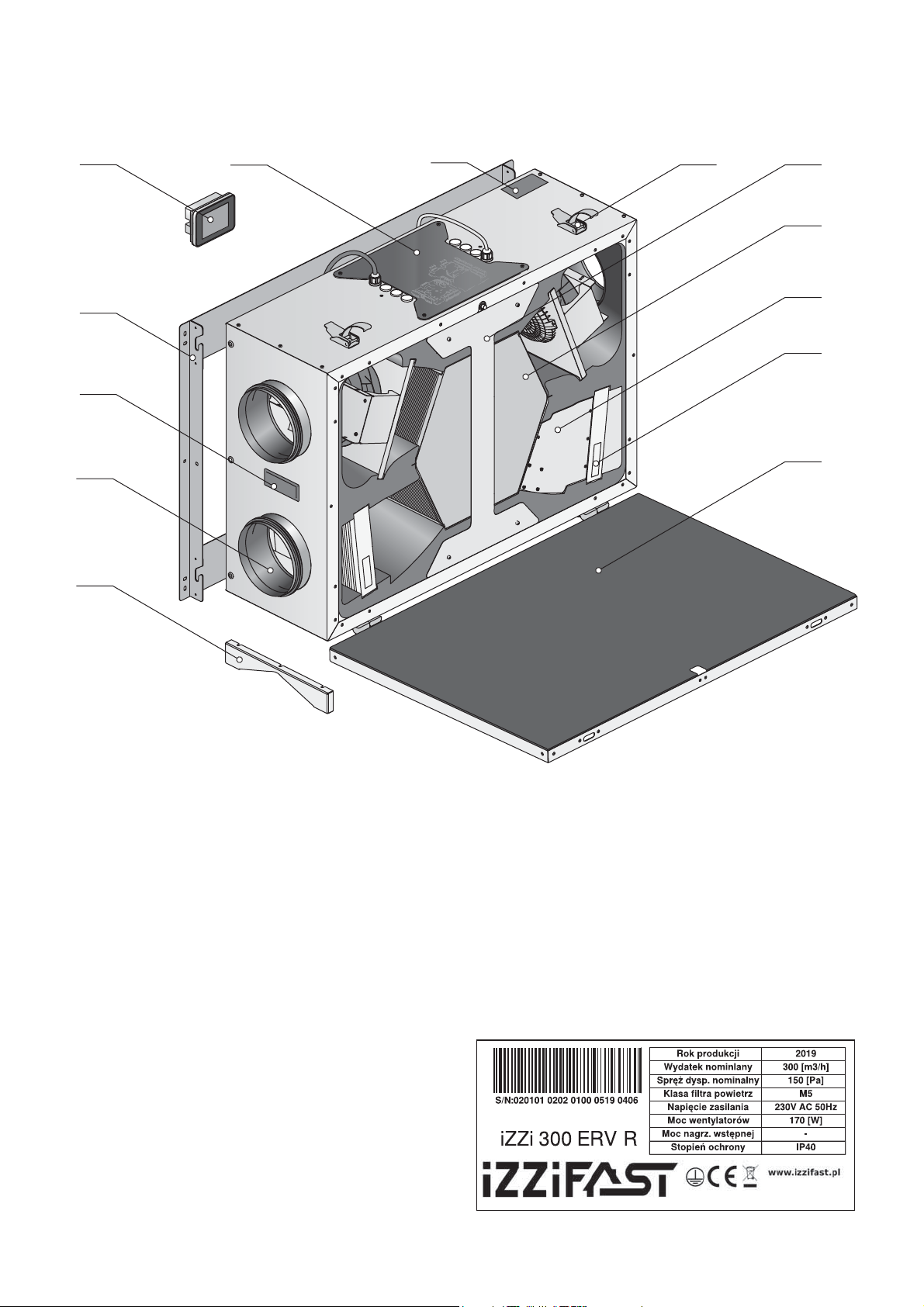
02.01 2.1 Design of iZZi 300 ERV R air handling unit (right
version). 4
02.01.1 Rating plate ............................................................4
02.02 Recuperator operation method................................5
02.03 Bypass.....................................................................5
02.04 Enthalpy heat exchanger..........................................5
02.05 Freeze protection system ........................................6
03 Dane techniczne.......................................................6
03.01 Flow characteristics ................................................7
03.02 Technical drawing of the recuperator....................... 7
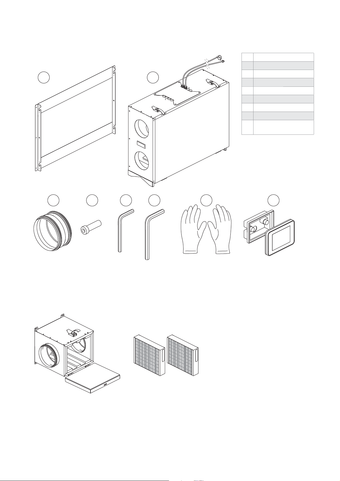
04 Scope of delivery..................................................... 8
04.01 Equipment...............................................................8
04.02 Optional equipment .................................................8
05 Planning....................................................................9
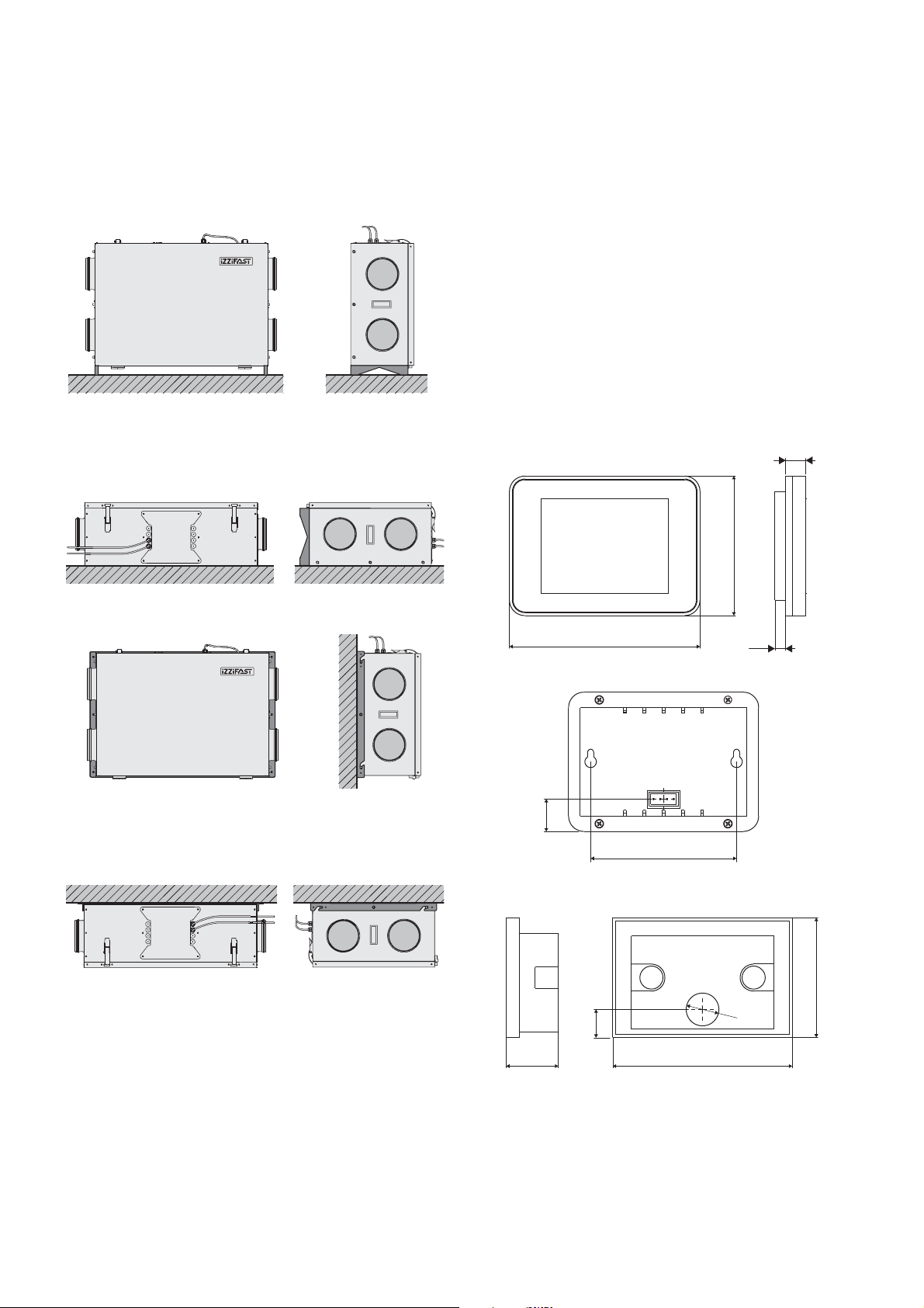
05.01 Methods of assembly ...............................................9
05.01.1 Vertical, on the floor ................................................9
05.01.2 Horizontal, on the floor ............................................9
05.01.3 On the wall...............................................................9
05.01.4 On a ceiling..............................................................9
05.02 Requirements for the assembly location ..................9
05.03 Electric connection .................................................9
05.04 Control panel ...........................................................9
05.05 Safe area ............................................................... 10
05.06 Anti-smog filter box - option.................................. 10
06 Assembly.................................................................11
06.01 Frame assembly...................................................... 11
06.02 Assembly of recuperator on frame .......................... 11
07 Automation............................................................. 12
07.01 IZZiFAST control engineering diagrams.................. 12
07.02 Control engineering revision...................................13
07.03 Touch panel ............................................................13
07.04 Ground-air heat exchanger .....................................13
07.05 Duct reheater ........................................................ 14
07.05.1 Electric reheater.................................................... 14
07.05.2 Water reheater .......................................................15
07.06 Duct cooler.............................................................15
07.06.1 Water duct cooler ...................................................15
07.07 Simultaneous connection of cooler and reheater. ...16
07.08 Preheater ...............................................................16
07.09 Humidity sensor (hygrostat) or doorbell switch button
for ventilation .........................................................17
07.10 CO (carbon dioxide) sensor or on/off button ...........17
07.11 Switch at the hood..................................................18
07.12 Fire alarm (control) panel ........................................18
08 User's manual for the controller with touch panel.. 19
08.01 Basic features of the controller...............................19
08.02 Main screen and operating mode presentation........19
08.03 STANDBY screen on the main panel ........................21
08.04 OPTIONS screen .....................................................21
08.05 Operating modes and performance settings............21
08.05.1 VENTILATION mode................................................21
08.05.2 OUT OF HOME mode................................................21
08.05.3 AIR PURIFICATION mode........................................22
08.05.4 AUTOMATIC mode ..................................................22
08.05.5 AUTOMATIC MODE SETTINGS
–WEEKLYPROGRAMME ........................................22
08.05.6 MANUAL SPEEDS AND CORRECTION SETTINGS.....22
08.05.6.1 Manual mode speeds .............................................22
08.05.6.2Programming of speeds used in the manual mode .22
08.05.6.3Software-based performance correction...............23
08.06 SETTINGS screen ..................................................23
08.06.1 Date and time settings...........................................24
08.06.2 Sound level and screen saver settings....................24
08.06.3 Language settings.................................................24
08.06.4 Inspection of filters condition................................24
08.06.5 Factory settings ....................................................25
08.06.6 Icon descriptions...................................................25
08.07 Peripheral devices and operation control...............25
08.07.1 Duct cooler operation control ................................25
08.07.2 Operation of the humidity sensor (hygrostat) or
doorbell switch button for ventilation.....................26
08.07.3 Duct cooler operation control ................................26
08.07.4 Ground-air heat exchanger (GWC) ..........................26
08.07.5 Control of bypass operation...................................26
08.07.6 Operation of CO sensor or "on/off" ventilation button
27
08.08 Information icon .................................................... 27
08.08.1 Contact ................................................................. 27
08.08.2 Ventilation system temperatures control screen.... 27
08.09 Alerts and messages..............................................28
08.09.1 Defrosting .............................................................28
08.09.2 Check the filters ....................................................28
08.09.3 Sensor damage......................................................28
08.09.4 Open cover ............................................................28
09 Service and maintenance...................................... 28
09.01 Filter replacement .................................................28
09.02 Removing the recuperator cover............................29
09.03 FAQ........................................................................29
10 Warranty conditions .............................................. 30