J. A. Roby CUISINIERE User manual

November 5, 2015 Printed in Canada
Tested and listed to
ULC STD S627-00
UL 1482-7
CAN/CSA STD B415.1-10
490, rue de l'Argon
Quebec, CANADA G2N 2C9
Tel.: 418-849-8095 Fax: 418-849-0077
www.jaroby.com
PLEASE READ CAREFULLY AND KEEP
THIS MANUAL FOR FUTURE REFERENCE
Instruction Manual
CUISINIERE

November 5, 2015 2
TABLE OF CONTENT
Introduction ............................................................................... 3
Rating plate .............................................................................. 4
Appliance dimensions .............................................................. 5
Installation ................................................................................ 6
Floor protection .................................................................... 6
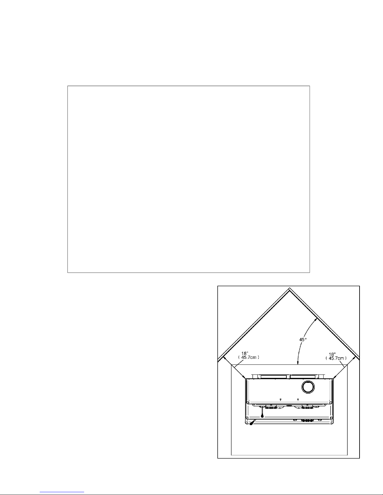
Minimum dimension of floor protection plate ................... 6
Clearances chart on floor plate ........................................ 7
Minimum clearances to combustible material ...................... 8
Assembly before installation ................................................ 9
Warming oven top Assembly ........................................... 9
Firebricks installation.......................................................... 11
Back firebricks installation ............................................. 11
Side firebricks installation .............................................. 11
Floor firebricks installation ............................................. 12
Firebricks installation on the pipes ................................. 12
General steps of stove installation ..................................... 14
Chimney connector installation .......................................... 15
Installation in a mobile home .................................................. 16
General steps of chimney installation ................................. 17
Vertical Installation Inside Masonry Chimney ................ 18
Outside Vertical Installation ........................................... 18
Vertical Installation on Cathedral Roof ........................... 19
Offset Vertical Installation .............................................. 19
Vertical Installation......................................................... 20
Combustion air intake ............................................................. 21
Exterior Air Intake pipe ....................................................... 21
Installation of Air Intake Pipe ......................................... 21
Air Inlet Obstruction ....................................................... 21
Replacement of stainless steel tubes ................................. 22
Installation of stainless steel tubes ................................ 22
Operating Instructions ............................................................ 23
Control of primary and secondary air admission ................ 2 3
Lightning fire ...................................................................... 23
First fire .............................................................................. 23
Keeping a fire ..................................................................... 23
Operation of cooking holes ................................................ 24
Storage of the cooking hole handle.................................... 24
Storage of warming oven handle ....................................... 24
Opening and closing of warming oven ............................... 25
Usage of oven for cooking ................................................. 25
Wood storage .................................................................... 25
Maintenance ........................................................................... 26
Ash Removal ................................................................. 26
Ash Disposal ................................................................. 26
Creosote Formation ....................................................... 26
Chimney Inspection ....................................................... 26
Chimney Sweeping ........................................................ 27
Door maintenance ......................................................... 27
Air Tighten Adjustment .................................................. 27
Cleaning up glass .......................................................... 27
Disassembly and reassembly of door ............................ 2 8
Replacing broken glass ................................................. 28
Replacing glass fiber rope ............................................. 28
What to do in case of Chimney Fire ....................................... 29
Annex 1 .................................................................................. 30
Door assembly ................................................................... 30
Wood Stove Door .......................................................... 30
Oven Door ..................................................................... 31
Annexe 2 ................................................................................ 32
Replacement parts ............................................................. 32
J. A. Roby Limited Lifetime warranty ...................................... 33

3
November 5, 2015
Introduction
Please read all the instructions carefully before installing your new J. A. ROBY CUISINIERE cook stove. A proper installation
is very important for a safe and effective use of your stove. If you have any doubts about the installation of your appliance,
we suggest to call a professional installer. A wrong installation may result in a fire, injury or loss of life.
Please keep this manual for future use.
This appliance must be connected to
A type HT chimney of 6 inch diameter (15.24 cm) listed to UL-103 or ULC-S629
A conforming masonry chimney of 6 inch diameter (15.24cm) with qualified internal lining
N.B: Please be aware that the local codes and regulations might be more specific than this manual. You can consult a
professional installer, the Fire Department or local authorities about restriction on installation of solid-fuel burning
appliances.
DO NOT CONNECT THIS APPLIANCE TO A CHIMNEY FLUE SERVING ANOTHER APPLIANCE.

4
November 5, 2015
Rating plate

5
November 5, 2015
Appliance dimensions

6
November 5, 2015
Installation
Floor protection
Your stove must be installed on a plate of non-combustible material to protect the floor and avoid fire caused by:
Projections of sparks at the moment of opening the door and loading;
The heat radiation of runaway which might cause self-ignition of floor and surface;
Possible creosote flow when there is a chimney fire.
UNITED STATES ONLY: The surface must be non-combustible and listed to the USA standard UL1618 or the local codes (Example:
cement, brick, ceramic tiles etc.)
Minimum dimension of floor protection plate
The following dimensions are the minimum values.
Canada:
49 7/8 in (126.6 cm)
66 3/8 in (168.6 cm)
3/8 in thickness (1 cm)
USA:
47 7/8 in (121.6 cm)
66 3/8 in (168.6 cm)
3/8 in thickness (1 cm)
UNITED STATES ONLY: It’s necessary to protect the floor beneath the horizontal part of chimney connector extending 2 inch (5cm)
beyond each side of the pipe. You can extend the floor protection panel while respecting the clearances of each side of stove.

7
November 5, 2015
Clearances chart on floor plate
The following dimensions are the minimums values.
Canada :
8 inches (20.3 cm) rear
8 inches (20.3 cm) side
18 inches (45.7 cm) loading door
USA :
8 inches (20.3 cm) rear
8 inches (20.3 cm) side
16 inches (40.6 cm) loading door

8
November 5, 2015
Minimum clearances to combustible material
This appliance needs a minimum space because of these reduced clearances. Whether in the living room or the dining room, the
CUISINIERE cook stove will match perfectly by its originality and heating. It requires a MINIMUM clearance of 12 inches at the back
(for a single pipe with a heat shield) and an 18 inch MINIMUM clearance on each side.
In case of a single pipe without heat shield, you must keep CUISINIERE cook stove 18 inches away from all
combustible material so that the MINIMUM clearance at the back of the stove will be 16¼ inches (41.3cm).
For a 45° corner installation, or other corner installation, the
minimum clearance between the cook stove and combustible
material must be 18 inches.

9
November 5, 2015
Assembly before installation
The stove leg and the warming oven top might not be assembled
in the factory, in order to save space for transportation and
storage. You must therefore assemble these parts before
installing the cook stove.
Warming oven top Assembly
At this moment, you need to know which type of smoke pipe you
are installing: a single pipe or a double pipe.
For the single pipe, it is not necessary to remove the pre-cut
metal part.
For the double pipe, you must remove the pre-cut metal part on
the top, inside and in front of the warmer, see pictures below.
1) Place the backside on the product package to protect
the painted part.
2) Fix the left side.
3) Fix the right side.
Couper le contour
Cut the edge
Couper le contour
Cut the edge
Couper le contour
Cut the ed
g
e

10
November 5, 2015
4) Attach the front part (with the door) to the two sides
and the back. Keep the horizontal holes for the
chrome decoration.
5) Insert the chrome decorations in the holes and fix
them with carriage bolt and nut (2 bolts each).
6) Fix the top with the back and the front. Do not fix the
chrome head now.
7) Insert the left decorative panel and attach it to the left
chrome decoration.
8) Fix the right decorative panel and attach it to the right
chrome decoration.
9) Remove the side panels of the cook stove.
10) Put and fix the warmer with the 4 bolts of each side to
the cook stove. 4 bolt extend out from the surface.
11) Fix the 2 carriage bolts at the front through the chimney
hole or the round cook opening.
12) Remove the screw on top and install the decorative
head.

11
November 5, 2015
Firebricks installation
Back firebricks installation
1) Place 4 bricks «A» and 1 brick «C» in the middle.
2) Set the 3 big screws in the holes for this purpose. Do not
tighten up these screws too much, so that washers will be
easily installed.
3) Add two bricks «A» horizontally on the 5 bricks.
4) Tighten the 3 screws.
Side firebricks installation
1) Put 3 bricks «A» on the right hand.
2) Place 2 screws and insert split washers.
3) Tighten the screws.
4) Repeat the same 3 steps to make the other side.

12
November 5, 2015
Floor firebricks installation
1) Place 2 bricks «A» in the bottom as shown in the picture.
2) After, insert 4 bricks «A» in front of the 2 bricks
previously installed.
3) Insert 1 brick «A» on the right of the ash dump plug.
4) Insert 1 brick «B» on the left of the ash dump plug.
Firebricks installation on the pipes
The firebricks must be placed on the 4 pipes from the bottom of
combustion chamber. Bricks keep a maximum heat inside the
combustion chamber so that the air coming from the pipes could
burn the entire gas coming out from wood, which is combustible
only in this way
The rockwool over the brick can prevent considerable leakage
between the bricks and keep a maximum heat inside combustion
chamber. It must cover up all the bricks and the each side of top
of the air corridor.
IMPORTANT: The rockwool must not obstruct the smoke exit.
Verify from the holes on the collar of the chimney to make sure
that it is in the right position. Then, place 2 stainless half round
plate as shown in the picture.
1) Place 2 bricks « A » over the two top pipes so that they
can be aligned lengthwise. Make sure that they are hold
properly on the bricks placed vertically at the back of the
combustible chamber and there is no space between
these bricks.
2) Place 4 bricks « A » over the two front pipes. It must be
placed as shown in the picture below. Be sure to leave
no space in between the bricks previously placed.

13
November 5, 2015
3) Put the rockwool over the bricks and verify from the
holes on the collar of the chimney to make sure the
smoke exit is not obstructed.
4) Place two stainless half round plate over the rockwool
by the rear deflector already in place.

14
November 5, 2015
General steps of stove installation
1) Read the entire installation manual before installing
and using your stove.
2) Choose a place to install your cook stove. Read the
sections about dimensions of floor protection panel,
localisation of stove over the floor protection panel, and
clearance to combustible materials. Once you have
decided where to install the stove, mark the center of
chimney on the floor.
o To make sure the vertical center of the
chimney, use a plumb line to mark on the
floor.
3) Check if it is possible to pass chimney without
damaging the structure of your house. You might have
to move the location of the stove while keeping the
minimum clearance. If you have to cut a joist, be sure
to respect the building code in effect to keep the
structural integrity of your house.
Note: This appliance have to be connected to:
A type HT chimney of 6 inch diameter (15.24 cm)
listed to UL-103 or ULC-S629.
A conforming masonry chimney of 6 inch
diameter (15.24cm) with qualified internal lining
4) Install the chimney following the manufacturer
instructions.
5) Put the stove on the floor aligned vertically with the
center of chimney, and trace the 4 sides of the stove
vertically on the floor. Please remove the stove.
6) Mark the dimensions of protection panel on the floor.
The edge clearance of the sides and the back is
8 inches (20.3 cm). At the front, it must be 16 inches
(40.6 cm) in US and 18 inches (45 cm) in Canada,
measured from the front door.
7) Install the floor protection panel according to the mark.
(It must be non-combustible)
8) Put the stove on the protection floor panel. Respect the
edge clearance that you have set at step 6 and the
centre of the chimney as well. We recommend to fix the
stove to the floor with bolt in the slots in the stove legs
made for this purpose. If you have a pedestal, use the
holes made for this purpose.
9) If you have an outside air inlet you must use 4 inches
(10.16 cm) flexible aluminum pipe. The pipe must be
sealed with thermal resistant sealant
10) Install the chimney connector from the stove. The pipe
must be attached with at least 2 screws, to the collars
of the stove and the chimney, also each joint of
connection.
Note:
The single or double wall chimney connector must
be 6 inch diameter (15,25 cm) and have a
minimum thickness of 24 gauge (0.025 inches
0.64 mm).
Do not use galvanised steel chimney connector.

15
November 5, 2015
Chimney connector installation
The chimney connector is a set of single or double wall flue pipes
and elbow installed between the stove collar and the chimney
collar. Components of single wall chimney connector are
available at any hardware store and there is no precise standard
or regulation. However, some rules must be followed to install
solid fuel burning equipment.
Double wall chimney connector
Your J.A. Roby CUISINIERE cook stove was approved for
the use of a single wall chimney connector with heat shield,
but it is possible to install a 6 inch (15.2 cm) double wall
certified chimney connector. In this case, you must detach
the pre-cut pieces of the top, the bottom and each side of
warming oven, in order to make holes for double wall
chimney connector.
We recommend to detach the removable pieces
before assembling the cook stove warmer.
ATTENTION:
For the clearance between combustible materials
and double wall chimney connector, see
manufacturer manual.
Single wall chimney connector
For the single wall chimney connector, you must use the
connector of 6 inch diameter with a minimum thickness of
24 gauge (0.025 inches 0.64 mm). For the section coming
out of the warming oven, install a metal heat shield,
covering the straight and curving sections with 1 inch (25.4
mm) thick.
ATTENTION:
If you don’t have heat shield, you must keep the
cook stove away in order to maintain the distance
of 18 inches or more from combustible materials.
Any horizontal section must be sloping upwards
1/4 inches (6.35 mm) by feet (30 cm) toward the
chimney collar. This section should not exceed
36 inches (91.4 cm).
The clearance between the roof and the single wall
chimney connector must be 18 inches (45.7 cm) or
more.
Regarding the clearance between the roof and the
double wall chimney connector, follow the
manufacturer indication.
1. Assembly of connecting parts
Make a brief installation of all sections and elbows (if necessary)
to ensure that you respect the clearances and inclinations of the
horizontal sections. You must also verify if you have all the
necessary parts for final installation.
o For direct vertical installation, you will need:
1 x vertical section of 24 inches (61 cm) or
more
1 x adequate length of telescopic chimney
part allowing you to connect the last chimney
connector section to the chimney collar.
Note: For higher roof, more parts might be needed.
o For horizontal installation, you will need:
1 x vertical section of 24 inches (61 cm) or
more;
1 x 90° elbow;
1 x adequate length of telescopic chimney
part.
Note: For better performance, two 45 degree elbows with
or without straight section in between are preferable.
2. Disassemble the whole thing and start screwing the pieces
from the stove to the roof chimney collar.
Couper le contour
Cut the edge
Couper le contour
Cut the ed
g
e
Couper le contour
Cut the edge

16
November 5, 2015
3. Insert entirely the roll formed end into the stove collar and
screwing it with a minimum of 3 screws.
WARNING: It is mandatory to attach the pipe to the
stove collar and also at each joint with at least of 3
screws.
4. Install all the next section up to the chimney support collar
and be sure to attach all parts with at least 3 screws.
ATTENTION: It is OBLIGATORY to attach the pipe on
the stove flue collar and each joint with at least 3
screws.
5. Install all other parts and attach them up to the chimney
collar.
6. Attach the connection pipe with 3 screws.
DO NOT CONNECT THIS APPLIANCE TO A CHIMNEY
SERVING ANOTHER APPLIANCE.
CONNECTOR PIPES SHOULD NEVER GO ACROSS A
CEILING, A WALL, A CLOSET, AN ATTIC OR OTHER
ENCLOSED AREA THAT COULD CAUSE HEAT
BUILDUP. IF YOU NEED TO PASS THROUGH
COMBUSTIBLE MATERIAL, MAKE SURE THAT YOUR
INSTALLATION COMPLIES WITH CAN / CSA-B365.
Installation in a mobile home
DO NOT INSTALL THIS APPLIANCE IN A
MOBILE HOME.

17
November 5, 2015
General steps of chimney installation
Use only approved chimneys of the same size as the output of
the appliance, which means 6 inches in the case of
CUISINIERE. The chimneys must be tested according to
CAN/ULC-S629-M87 in Canada and to UL-103 (type HT) In
USA. The CUISINIERE can be installed with a masonry chimney
according to ULC-S635, ULC-S640 and UL-1777. The masonry
chimney must be equipped with a stainless steel sleeve and
meet the standards for the masonry chimney with inner sleeve.
Provide a place for sweeping.
It is preferable, if possible, to avoid a chimney built outside of a
house and on an exterior wall, especially in cold regions.
Outside chimneys generally have a less efficient draft. They can
even have down draft since it is hard to heat them enough so
that they can reach their operating temperature. Cold chimneys
have tendencies of greater accumulation of creosote, less
efficient draft and worse efficiency. Draft is proportional to the
total chimney height as well as its temperature. It is therefore
possible to get better draft by increasing the chimney's height
and by reducing the heat loss with insulated lining. Make sure
that all pipe joints are really airtight. A leak reduces the efficiency
of the appliance and could even make its usage dangerous.
Note: This is a general chimney installation method. Be
sure to refer to the manufacturer’s manual for more details
of installation of your chimney.
1) Determine the total length necessary for your
chimney.
2) Make holes into all floors and roof.
3) If you need to cut a joist, be sure to strengthen the
adjacent joists and frame the hole respecting
the minimum dimensions between
combustible materials and the fireguard.
Follow the manufacturer's instructions
supplied with the fireguard. Never cut a
loadbearing joist/beam.
4) Frame the holes in each level and attic
respecting the minimum distance
recommended by the manufacturer of your
chimney. Install fireguard in each level.
5) Frame the hole into the roof.
6) Install a chimney support and a fireguard in
the ceiling where cook stove is installed.
7) Stack the prefabricated chimney sections on the
support and exceed the roof.
The chimney must exceed at least 3 feet
(91.4 cm) from the highest point of the hole
in the roof.
The chimney must also be at least 2 feet
over the highest point on the roof inside
10 feet (304 cm) radius around the chimney.
The minimum length of chimney is 12 feet
(365.8 cm).
ATTENTION: Be sure the chimney parts
are attached properly and lock onto the
chimney support.
Note: A chimney longer than the
minimum required can add more draft
and help the operation of the cook stove.
Try the minimum length first then add
section if you need more draft.
8) Put the roof flashing over the chimney and seal it with
roof caulking.
9) Nail the roof flashing.
10) Slide the storm collar over the chimney and fix it. Seal
it with high temperature caulking.
11) Lock the chimney cap and install the spark arrestor if
necessary.

18
November 5, 2015
Vertical Installation Inside Masonry
Chimney
The CUISINIERE cook stove must be installed in accordance
with the applicable local laws or the standards such as ULC-
S635, ULC-S640, and NFPA 211 (USA). Follow the chimney
manufacturer’s instructions to install the chimney.
Outside Vertical Installation
The CUISINIERE cook stove must be installed in
accordance with the applicable local laws or the CAN/CSA-
B365, NFPA 211 (USA). Follow the chimney
manufacturer’s instructions to install the chimney.

19
November 5, 2015
Vertical Installation on Cathedral Roof
The CUISINIERE cook stove must be installed in accordance
with the applicable local laws or the CAN/CSA-B365,
NFPA 211 (USA). Follow the chimney manufacturer’s
instructions to install the chimney.
.
Offset Vertical Installation
The CUISINIERE cook stove must be installed in accordance
with the applicable local laws or the CAN/CSA-B365,
NFPA 211 (USA). Follow the chimney manufacturer’s
instructions to install the chimney.

20
November 5, 2015
Vertical Installation
The CUISINIERE cook stove must be installed in accordance
with the applicable local laws or the CAN/CSA-B365,
NFPA 211 (USA). Follow the chimney manufacturer’s
instructions to install the chimney.
Other manuals for CUISINIERE
1
Table of contents
Other J. A. Roby Stove manuals
Popular Stove manuals by other brands

Pacific energy
Pacific energy trenton A series Installation and operating instructions

ACR STOVES
ACR STOVES Solis SOLMF Technical manual

Coopers
Coopers G156 Instructions for use

Blaze King
Blaze King Pegasus 9200 Owner's installation and operation manual

Palazzetti
Palazzetti ECOMONOBLOCCO WT 78F V DESCRIPTION / CLEANING / TECHNICAL DATA

Dometic
Dometic ORIGO 2000 operating manual