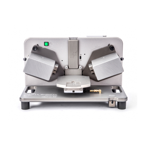
J.A. Woollam M-2000 User manual

M-2000®
Spectroscopic
Ellipsometer
Hardware Manual
Auto-Angle ESM-300 Base
CompleteEASE®Software

2 ©2023 J.A. Woollam Co. M-2000® Hardware Manual

©2023 J.A. Woollam Co. All rights reserved.
J.A. Woollam Co.
311 South 7th Street
Lincoln, NE 68508
USA
Ph: 1.402.477.7501
Fx: 1.402.477.8214
www.jawoollam.com
Thank you for purchasing a J.A. Woollam Co. Spectroscopic Ellipsometer. We hope the
information contained in this manual will help you develop a better understanding and
appreciation for the ellipsometer and any accessories purchased.
The contents of this manual are subject to change without notice and do not constitute a
commitment on the part of J.A. Woollam Co. Every effort has been made to ensure the
accuracy of this document. However, due to ongoing product improvements and revisions, J.A.
Woollam Co. cannot guarantee the accuracy of the printed material after the date of
publication nor can it accept responsibility for errors or omissions. J.A. Woollam Co. will update
and revise this document as needed.
Copying and Distribution
You are welcome to make backup copies of this manual for your own use and protection.
However, you are not permitted to make copies for others or for resale.
Trademarks
CompleteEASE and M-2000 are registered trademarks of the J.A. Woollam Co. All other
trademarks used within are the property of their respective owners.


M-2000® Hardware Manual ©2023 J.A. Woollam Co. v
Contents
1Safety Instructions .......................................................................................... 11
1.1 Message Boxes.................................................................................................................. 11
1.2 General Safety Instructions............................................................................................... 11
1.3 Environmental Operating Range....................................................................................... 12
2Hardware Description..................................................................................... 13
2.1 System Configurations...................................................................................................... 13
2.2 System Components ......................................................................................................... 13
Source Units ..................................................................................................................................................13
Receiver Units................................................................................................................................................18
Fiber Optic Cables..........................................................................................................................................19
Detector/Lamp Power Control Module.........................................................................................................20
Electronics Control (EC) Module ...................................................................................................................20
Computer ......................................................................................................................................................21
Surge Suppressor...........................................................................................................................................21
USB Camera (Optional)..................................................................................................................................21
Auto-Angle ESM-300 Base Unit.....................................................................................................................21
Power Control Module (Optional).................................................................................................................22
3Installation...................................................................................................... 23
3.1 System Assembly .............................................................................................................. 23
Preliminary ....................................................................................................................................................23
Base Assembly...............................................................................................................................................25
AC Wiring.......................................................................................................................................................29
Cabling...........................................................................................................................................................31
Computer ......................................................................................................................................................33
Rack Mount Table Option..............................................................................................................................33
System Enclosure Option ..............................................................................................................................36
Lamp Installation (if applicable) ....................................................................................................................41
3.2 Electronics Control (EC) Module Setup............................................................................. 42
Configuring the EC Module ...........................................................................................................................42
3.3 Operator Computer Setup................................................................................................ 43
Software Installation .....................................................................................................................................44
Windows Network Setup ..............................................................................................................................44
USB Camera...................................................................................................................................................46
High Performance Mode ...............................................................................................................................49
4Preparing the System for Use ......................................................................... 51
4.1 Power up Procedure ......................................................................................................... 51
4.2 Conventions Used in this Manual ..................................................................................... 52
4.3 File Organization & Manipulation..................................................................................... 53
4.4 Operation.......................................................................................................................... 53
System Alignment .........................................................................................................................................54

vi ©2023 J.A. Woollam Co. M-2000® Hardware Manual
Sample Alignment .........................................................................................................................................57
System Check (Calibration)............................................................................................................................57
4.5 System Alignment (with Manual Tip/Tilt)......................................................................... 58
Source Unit Alignment ..................................................................................................................................59
Receiver Unit Alignment................................................................................................................................61
Verify Signal...................................................................................................................................................63
4.6 System Alignment (with Automated Tip/Tilt)................................................................... 66
Source Unit Alignment ..................................................................................................................................68
Receiver Unit Alignment................................................................................................................................69
Verify Signal...................................................................................................................................................71
Sample Stage Alignment ...............................................................................................................................74
Lookdown Detector Alignment .....................................................................................................................77
4.7 Sample Alignment (with Manual Tip/Tilt)......................................................................... 82
4.8 Sample Alignment (with Automated Tip/Tilt) .................................................................. 84
4.9 System Check (Calibration)............................................................................................... 85
Evaluating Calibration Results.......................................................................................................................87
4.10 Instrument Shutdown....................................................................................................... 88
5Data Acquisition.............................................................................................. 89
5.1 Acquiring Ellipsometric Data............................................................................................. 89
5.2 Recipes.............................................................................................................................. 92
Prompt for Recipe Components....................................................................................................................93
Creating New Recipes....................................................................................................................................94
Creating New Acquisition Parameters ..........................................................................................................95
Creating New Analysis Models ......................................................................................................................95
Using a Recipe ...............................................................................................................................................95
5.3 Data Types......................................................................................................................... 97
Standard ........................................................................................................................................................97
Mueller Matrix...............................................................................................................................................98
Reflection Intensity .......................................................................................................................................99
5.4 Routine Test Measurements........................................................................................... 101
Initial Setup .................................................................................................................................................101
Viewing Results ...........................................................................................................................................102
6Focusing Optics............................................................................................. 103
6.1 General Overview ........................................................................................................... 103
6.2 Installation ...................................................................................................................... 104
Standard Receiver Unit................................................................................................................................105
Alignment Camera Receiver Unit ................................................................................................................108
6.3 Lens Correction............................................................................................................... 110
6.4 Sample Alignment & System Check with Focusing Optics.............................................. 111
6.5 Data Acquisition with Focusing Optics ........................................................................... 113
6.6 Removal .......................................................................................................................... 114
7Automated Translation (Optional) ................................................................ 115

M-2000® Hardware Manual ©2023 J.A. Woollam Co. vii
7.1 General Operation .......................................................................................................... 115
7.2 Scan Patterns .................................................................................................................. 116
Substrate Dimensions..................................................................................................................................117
Point List and Point Commands ..................................................................................................................117
Grid and Line Fill..........................................................................................................................................119
Test Scan .....................................................................................................................................................120
Alignment Position ......................................................................................................................................121
Save .............................................................................................................................................................121
7.3 Rotator Option................................................................................................................ 122
Wobble Correction ......................................................................................................................................123
8Sample Camera............................................................................................. 125
Illumination Control ....................................................................................................................................125
8.1 Marking the Measurement Beam Position..................................................................... 126
8.2 Field of View Calibration................................................................................................. 134
9In Situ137
10 Scheduled Maintenance ............................................................................... 139
10.1 D2 & QTH Lamps (M-2000D, DI, U, & UI) in XLS-200...................................................... 139
Lamp Installation/Replacement ..................................................................................................................139
Lamp Alignment ..........................................................................................................................................141
10.2 Xe Lamp (M-2000X, XI, X-210, & XI-210) in FLS-860....................................................... 141
Lamp Installation/Replacement ..................................................................................................................142
Lamp Alignment ..........................................................................................................................................145
Arc Lamp Disposal .......................................................................................................................................147
Mirror Replacement ....................................................................................................................................147
10.3 QTH Lamp (M-2000V & VI) in FQTH-100 ........................................................................ 148
Lamp Installation/Replacement ..................................................................................................................148
Lamp Alignment ..........................................................................................................................................150
10.4 Optical Fiber.................................................................................................................... 151
10.5 Cleaning........................................................................................................................... 151
11 Performance Checks ..................................................................................... 153
11.1 Calibration Wafer & Straight-Through Measurement.................................................... 153
11.2 System Check .................................................................................................................. 155
11.3 Verify Sample Alignment ................................................................................................ 155
11.4 Verify Signal/Lamp Intensity........................................................................................... 156
11.5 Verify System Alignment................................................................................................. 156
11.6 Angle of Incidence Offset Correction.............................................................................. 157
11.7 System Calibration .......................................................................................................... 157
Overview .....................................................................................................................................................158
System Calibration ......................................................................................................................................158
Wavelength Calibration...............................................................................................................................163
12 Troubleshooting............................................................................................ 165

viii ©2023 J.A. Woollam Co. M-2000® Hardware Manual
12.1 General Procedures ........................................................................................................ 165
Debug File....................................................................................................................................................165
12.2 Common Screen Error Messages.................................................................................... 166
Phase Sensor Error Message .......................................................................................................................166
Polarizer Homing Error Message.................................................................................................................167
Spectrometer Is Not Scanning.....................................................................................................................167
Communication Problems...........................................................................................................................167
12.3General Problems ........................................................................................................... 168
12.4 Software Problems and Error Messages......................................................................... 169
12.5 Calibration Problems....................................................................................................... 169
12.6 Signal Screen Problems................................................................................................... 169
12.7 Lamp and Light Problems................................................................................................ 170
12.8 USB Camera .................................................................................................................... 171
13 Specifications................................................................................................ 173
13.1 Components.................................................................................................................... 173
Electronics Control (EC) Module .................................................................................................................173
Detector / Lamp Power Supply Modules ....................................................................................................174
Power Control Module ................................................................................................................................176
Surge Suppressor.........................................................................................................................................178
Computer ....................................................................................................................................................178
Monitor .......................................................................................................................................................178
13.2 Environmental Operating Range..................................................................................... 178

M-2000® Hardware Manual ©2023 J.A. Woollam Co. ix


M-2000® Hardware Manual ©2023 J.A. Woollam Co. 11
1Safety
Instructions
1.1 Message Boxes
Three message boxes are used in this manual. They are explained below:
Warning: This box is used to warn the user of a potential hazard to the user or
persons in the area of the ellipsometer.
Caution: This box is used to alert the user that an incorrect operation or
procedure could cause damage to the equipment.
Note: This box contains tips, hints, and useful information relating to the
procedure in which it is located.
1.2 General Safety Instructions
Warning: For safe operation of this equipment, do not use it in any way other
than what is described in this user’s manual or as recommended by
the manufacturer.
Keep hands/fingers/body parts away from the instrument while making
motor position changes. Pinch points may be applicable (see below).

12 ©2023 J.A. Woollam Co. M-2000® Hardware Manual
Figure 1-1. Potential pinch points.
Ensure all system controls and power cables are tied/tucked
away/hidden/kept away/arranged such that persons walking around the
instrument area will not snag or trip on any of the cables.
Replace bad fuses only with proper type and rated fuse.
Never look into a tip of an optical fiber.
Never look directly at an operating lamp, severe eye injury may result.
Wear UV protective lenses, such as a welder’s helmet, when working
around operating lamps.
Permanent eye damage can result from looking directly into the beam. It
is best to view the beam using a piece of paper or business card.
Before servicing this equipment, ensure that the power source is
disconnected.
Before servicing the lamp housing, be sure to disconnect all cables. Make
certain the lamp is at room temperature (turn lamp off for at least 20
minutes).
Compact arc lamps contain highly pressurized gas, and present an
explosion hazard even when cold. Wear face protection, such as a full-
face shield, gloves and a long sleeve shirt whenever handling lamps.
1.3 Environmental Operating
Range
Temperature: 10°C to 35°C
Humidity: 20% to 80% (non-condensing)

M-2000® Hardware Manual ©2023 J.A. Woollam Co. 13
2Hardware
Description
2.1 System Configurations
This manual covers the full line of M-2000 based spectroscopic ellipsometers
mounted on the auto-angle ESM-300 base.
MODEL
SPECTRAL RANGE
LAMP(S)
M-2000D(I)
193-1000 (1690) nm
30W Deuterium and 20W QTH
M-2000X(I)
210 (245)-1000 (1690) nm
75W Xenon arc
M-2000U(I)
245-1000 (1690) nm
30W Deuterium and 20W QTH
M-2000V(I)
370-1000 (1690) nm
50W QTH
Table 2-1. M-2000 models, spectral range, and lamp(s).
2.2 System Components
The M-2000 spectroscopic ellipsometer system is based on advanced Diode
Array Rotating Compensator Ellipsometer (DARCETM) technology from the J.A.
Woollam Co. This technology provides consistently accurate ellipsometric data,
independent of the sample characteristics.
Source Units
The following source units are used for M-2000 ellipsometers.

14 ©2023 J.A. Woollam Co. M-2000® Hardware Manual
XLS-200 Source Unit
Figure 2-1. XLS-200 Source Unit.
M-2000D(I) and M-2000U(I) ellipsometers use the XLS-200 Source Unit. The XLS-
200 Light Source houses the D2 (Deuterium) and QTH (Quartz Tungsten Halogen)
lamps. Power for the lamps is supplied through highly regulated switching DC
power supplies located in the M-2000 XLS light source. The Source Unit also
contains the beam collimation optics, a fixed polarizer, and a compensator
located in a continuously rotating stepper motor.
30 watt D2 Lamp
Figure 2-2. D2 lamp.
The D2 (Deuterium) lamp supplies light from the UV to the visible region of the
spectrum. This lamp is mounted just behind the shutter aperture.

M-2000® Hardware Manual ©2023 J.A. Woollam Co. 15
20 watt QTH lamp
Figure 2-3. QTH lamp.
The QTH (Quartz Tungsten Halogen) lamp supplies light from the visible to the
NIR region of the spectrum. This lamp is mounted just behind the D2 lamp
aperture.
Warning: The D2 and QTH lamps get extremely hot during operation. Always
allow them to cool adequately before replacing them.
FLS-860 Source Unit
Figure 2-4. FLS-860 Source Unit.
M-2000X(I) ellipsometers use the FLS-860 Source Unit. The FLS-860 Light Source
houses the 75W Xenon arc lamp and igniter circuitry. The Source Unit also
contains the beam collimation optics, a fixed polarizer, and a compensator
located in a continuously rotating stepper motor.

16 ©2023 J.A. Woollam Co. M-2000® Hardware Manual
75 watt Xenon Arc Lamp
Figure 2-5. Typical arc lamp.
The Arc Lamp is a high pressure Xenon discharge point source lamp. It is filled
with Xenon gas at above atmospheric pressure. The lamp is mounted in an inner
enclosure within the source unit.
Warning: Compact arc lamps contain highly pressurized gas, and present an
explosion hazard even when cold. Wear face protection, such as a
welder’s helmet, whenever handling lamps.
Warning: The Xe arc lamp gets extremely hot during operation. Always allow
it to cool adequately before replacing the lamp.
Neutral Density Filter Wheel (Optional)
The Source Unit may include an optional neutral density (ND) filter wheel (auto
or manual). The auto filter wheel is controlled by the software and can be set to
auto select the intensity level by checking the "Auto" box. This is used to select
the optimum intensity level for the sample under measurement.
The intensity can also be set by the user to a specified value by un-checking the
"Auto" box and selecting the filter value from the drop down menu. This can be
helpful during system alignment.
Figure 2-6. Auto Filter Wheel intensity selection option.

M-2000® Hardware Manual ©2023 J.A. Woollam Co. 17
The manual filter wheel option has eight (8) detent positions:
POSITION
INTENSITY
0
100%
1
70%
2
50%
3
20%
4
10%
5
5%
6
3%
7
Yellow –Long Pass filter at 530nm
Table 2-2. Manual Filter Wheel positions.
Rotate the filter wheel to select the amount of light intensity needed for the
sample under measurement.
Figure 2-7. Source Unit Manual Filter Wheel.
FQTH-100 Source Unit
Figure 2-8. FQTH-100 Source Unit.
Filter shown at the 100%
light throughput position

18 ©2023 J.A. Woollam Co. M-2000® Hardware Manual
M-2000V(I) ellipsometers use the FQTH-100 Source Unit. The FQTH-100 Light
Source houses a 50W QTH (Quartz Tungsten Halogen) lamp. The Source Unit
also contains the beam collimation optics, a fixed polarizer, and a compensator
located in a continuously rotating stepper motor.
50 watt QTH Lamp
Figure 2-9. Typical QTH lamp.
The QTH (Quartz Tungsten Halogen) lamp is mounted just behind the pinhole in
the rear of the lamp housing.
Warning: The QTH lamp gets extremely hot during operation. Always allow it
to cool adequately before replacing the lamp.
Receiver Units
The following receiver units are used for M-2000 ellipsometers. There is also an
optional Internal Alignment Camera used for fast sample alignment.
MQD-Single Receiver Unit
Figure 2-10. MQD Single Receiver Unit.
The MQD Single Receiver Unit is used on the M-2000D, U, X, and V systems. It
consists of a stepper motor driven rotational stage which houses an analyzer.
There is also a four-quadrant detector used for alignment of the system. This
receiver contains one beam folding mirror and one fiber coupling lens (UV-VIS).

M-2000® Hardware Manual ©2023 J.A. Woollam Co. 19
MQD-Dual Receiver Unit
Figure 2-11. MQD Dual Receiver Unit.
The MQD Dual Receiver Unit is used on the M-2000DI, UI, XI, and VI systems. It
consists of a stepper motor driven rotational stage which houses an analyzer.
There is also a four-quadrant detector used for alignment of the system. This
receiver contains two beam folding mirrors and two fiber coupling lenses (UV-VIS
& VIS-NIR).
Fiber Optic Cables
Figure 2-12. Optical fiber.
Fiber Optic Cables are used to couple the beam from the Receiver Unit to the
Detector(s) located in the M-2000 Detector and Lamp Power Supply Module.
The fibers have a 200 micron core diameter (standard), and are terminated on
each end with an SMA connector for easy insertion and removal.
One DUV fiber is used in M-2000D, U, and X systems. M-2000V systems use one
IR fiber since the spectrum is limited to 370nm. If the ellipsometer system has
NIR extension, a second fiber is used for the NIR Detector. Fibers are normally 2
or 3 meters long, depending on application.
SMA Connector
Protective
Endcap
Fiber

20 ©2023 J.A. Woollam Co. M-2000® Hardware Manual
Note: When the fiber is first installed it needs to be oriented for maximum
light throughput. This is covered in Chapter 10 Scheduled
Maintenance.
Caution: Proper handling of the fiber is necessary to ensure long lifetime.
When removing the protective rubber end cap, hold the end cap
and pull the SMA connector nut. Do not pull directly on the fiber.
Never allow the fiber tip to contact any other surface (fingertip,
tabletop, etc.). Always cover the tips with protective rubber end
caps when the fiber is not in use. The bend radius of the fiber
should never be smaller than two inches. Never use a tool to
tighten the fiber - it should only be finger-tight.
Detector/Lamp Power Control Module
Figure 2-13. M-2000 Detector and Lamp Power Supply Module.
The M-2000 Detector and Lamp Power Supply Module contains a UV-VIS
Spectrometer covering a wavelength range of 193-1000 nm and an optional NIR
Spectrometer that covers a wavelength range of 1000-1690 nm. It also contains
highly regulated DC switching power supply for the Light Source. The switching
power supply provides a very stable source of power for the system lamp(s).
Electronics Control (EC) Module
Figure 2-14. Electronics Control Module.
The Electronics Control Module contains a 486DX2 embedded computer. This
computer is responsible for controlling the analog-to-digital (A/D) converter, the
stepper motor drivers, and communicating with the host computer via a network
card.
This manual suits for next models
4
Table of contents
Other J.A. Woollam Measuring Instrument manuals