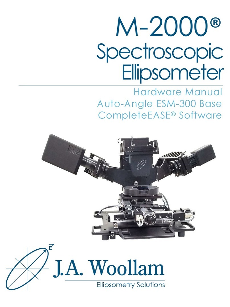
J.A. Woollam alpha-SE User manual

alpha-SE®
Spectroscopic
Ellipsometer
Hardware Manual


Copyright © 2004-2018 J.A. Woollam Co. All Rights Reserved.
J.A. Woollam Co.
645 M Street, Suite 102
Lincoln, NE 68508
USA
Ph: 402.477.7501
Fx: 402.477.8214
www.jawoollam.com
Thank you for purchasing a J.A. Woollam Co. Spectroscopic Ellipsometer. We hope the information
contained in this manual will help you develop a better understanding and appreciation for the
alpha-SE hardware.
The contents of this manual are subject to change without notice and do not constitute a
commitment on the part of J.A. Woollam Co. Every effort has been made to ensure the accuracy of
this document. However, due to ongoing product improvements and revisions, J.A. Woollam Co.
cannot guarantee the accuracy of the printed material after the date of publication nor can it
accept responsibility for errors or omissions. J.A. Woollam Co. will update and revise this
document as needed.
Copying and Distribution
You are welcome to make backup copies of the CompleteEASE software and documentation for
your own use and protection. However, you are not permitted to make copies for others or for
resale.
Trademarks
CompleteEASE and alpha-SE are trademarks of J. A. Woollam Co. All other trademarks used within
are the property of their respective owners.


alpha-SE Hardware Manual Contents
iii
Contents
1. Safety Instructions 1-1
1.1. Message Boxes.........................................................................................................1-1
1.2. General Safety Instructions ......................................................................................1-1
1.3. Environmental Operating Range ..............................................................................1-2
2. Quick Guide 2-1
2.1. Manual Overview.....................................................................................................2-1
2.2. Quick Setup..............................................................................................................2-3
1. Unpack and assemble the instrument ................................................................2-3
2. Install, activate, and run CompleteEASE software ...........................................2-3
3. Check the beam and calibrate the system..........................................................2-4
4. Collect data .......................................................................................................2-5
3. System Installation 3-1
3.1. alpha-SE Specifications............................................................................................3-1
Measurement Capabilities ........................................................................................3-1
Data Analysis Capabilities .......................................................................................3-1
3.2. Facilities Requirements ............................................................................................3-2
3.3. Unpacking the Hardware..........................................................................................3-3
Opening the Shipping Container ..............................................................................3-3
Attaching the Sample Chuck....................................................................................3-4
Releasing the Z-stage Shipping Lock.......................................................................3-5
3.4. Installing the Software..............................................................................................3-7
Before Installation ....................................................................................................3-7
Running the SETUP Program...................................................................................3-7
Operating Hardware ...............................................................................................3-12
3.5. Activating the Software..........................................................................................3-13
3.6. Connecting the alpha-SE ........................................................................................3-13
Verifying the alpha-SE Driver Installation.............................................................3-14
3.7. Running the CompleteEASE Software...................................................................3-15
3.8. Learning Data Analysis..........................................................................................3-16
4. Initial System Checks and Calibration 4-1
4.1. Initial System Operation...........................................................................................4-1
alpha-SE System Components..................................................................................4-1
Changing the Angle of Incidence (AOI) ..................................................................4-2
4.2. Checking Beam Alignment at 90°............................................................................4-4
4.3. Checking Signal Intensity.........................................................................................4-5
Low Intensity............................................................................................................4-5
High Intensity...........................................................................................................4-5
4.4. Checking Straight-Through SE Data Accuracy........................................................4-6
4.5. Measuring the Reference Wafer...............................................................................4-7
4.6. S-T Baseline ...........................................................................................................4-10
4.7. Off-Sample Baseline ..............................................................................................4-12
4.8. Calibrating the Angle of Incidence.........................................................................4-14
4.9. Powering Down......................................................................................................4-18
5. Data Collection 5-1

iv
Contents alpha-SE Hardware Manual
5.1. Measurement Tab Overview ....................................................................................5-1
5.2. Off-Sample Measurements.......................................................................................5-3
Measuring a Sample .................................................................................................5-3
5.3. Straight-Through Measurements ..............................................................................5-5
5.4. Mueller-matrix Measurements .................................................................................5-7
6. Hardware Tab 6-1
6.1. Hardware..................................................................................................................6-1
Re-initialize ..............................................................................................................6-1
Park Z-Stage.............................................................................................................6-1
6.2. Signal........................................................................................................................6-2
Display .....................................................................................................................6-2
Max. Sig. Display.....................................................................................................6-2
Z-Stage Scan.............................................................................................................6-2
6.3. Calibration................................................................................................................6-3
S-T Baseline .............................................................................................................6-3
Off-Sample Baseline ................................................................................................6-3
Angle Offsets............................................................................................................6-4
6.4. Show Logs................................................................................................................6-4
Hardware and Error Logs .........................................................................................6-4
6.5. Camera .....................................................................................................................6-5
Show Image Dialog..................................................................................................6-5
Mark Beam Position.................................................................................................6-6
Illumination On ........................................................................................................6-7
6.6. Routine Test Measurement.......................................................................................6-7
Measure....................................................................................................................6-8
Show Results............................................................................................................6-8
6.7. Configuration Files...................................................................................................6-8
hardware.cnf.............................................................................................................6-8
Privileges.cnf............................................................................................................6-9
Alpha-cal.cnf............................................................................................................6-9
Motorinfo.cnf ...........................................................................................................6-9
CompleteEASE.cnf and CompleteEASEhard.cnf ....................................................6-9
7. Accessories 7-1
7.1. Focusing ...................................................................................................................7-1
Tips when using focus probes: .................................................................................7-1
How to test focus probe alignment:..........................................................................7-2
Before attempting to align focus probes:..................................................................7-2
Aligning focus probes: .............................................................................................7-3
7.2. Camera .....................................................................................................................7-4
Installation................................................................................................................7-5
7.3. Liquid Cell................................................................................................................7-6
7.4. Transmission Mount.................................................................................................7-7
7.5. Manual Translation...................................................................................................7-7
7.6. QCM Adaptor...........................................................................................................7-8
8. Service and Troubleshooting 8-9
8.1. Lamp Change Procedure ..........................................................................................8-9
8.2. Upgrading CompleteEASE ....................................................................................8-10
8.3. Troubleshooting Guide...........................................................................................8-10
Creating a Debug file..............................................................................................8-12

alpha-SE Hardware Manual Contents
v
9. Appendices 9-1
9.1. Spectroscopic Ellipsometry......................................................................................9-1
Ellipsometry Advantages..........................................................................................9-2
Intensity Measurements............................................................................................9-2
Mueller-matrix Measurements .................................................................................9-3
Determining Sample Properties (Data Analysis)......................................................9-4
Film Thickness .........................................................................................................9-4
Ultra-Thin Films (<10nm)........................................................................................9-6
Optical Constants .....................................................................................................9-6
Additional References ..............................................................................................9-7
9.2. Conventions Used in this Manual.............................................................................9-7
Tabs..........................................................................................................................9-8
Screen Panels............................................................................................................9-8
Buttons .....................................................................................................................9-8
9.3. Short-cut Guide ........................................................................................................9-9
9.4. Contacting J.A. Woollam Co..................................................................................9-11
10. Index 1


alpha-SE Hardware Manual Safety Instructions
1-1
1. Safety Instructions
1.1. Message Boxes
Three message boxes are used in this manual. They are explained below:
Warning: This box is used to warn the user of a potential hazard to
the user or persons in the area of the ellipsometer.
Caution: This box is used to alert the user that an incorrect
operation or procedure could cause damage to the
equipment.
Note: This box contains tips, hints, and useful information
relating to the procedure in which it is located.
1.2. General Safety Instructions
Warning: For safe operation of this equipment, do not use it in any
way other than what is described in this user’s manual or
as recommended by the manufacturer.
Keep hands/fingers/body parts away from the instrument while
making motor position changes.
Ensure all system controls and power cables are tied/tucked
away/hidden/kept away/arranged such that persons walking
around the instrument area will not snag or trip on any of the
cables.
Replace bad fuses only with proper type and rated fuse.
Never look into a tip of an optical fiber.
Never look directly at an operating lamp, severe eye injury may
result. Wear UV protective lenses, such as a welder’s helmet, when
working around operating lamps.

1-2
Safety Instructions alpha-SE Hardware Manual
Permanent eye damage can result from looking directly into the
beam. It is best to view the beam using a piece of paper or business
card.
Before servicing this equipment, ensure that the power source is
disconnected.
Before servicing the lamp housing, be sure to disconnect all cables.
Make certain the lamp is at room temperature (turn lamp off for at
least 20 minutes).
Compact arc lamps contain highly pressurized gas, and present an
explosion hazard even when cold. Wear face protection, such as a
full-face shield, gloves and a long sleeve shirt whenever handling
lamps.
1.3. Environmental Operating Range
Temperature: 10°C to 35°C
Humidity: 20% to 80% (non-condensing)

alpha-SE Hardware Manual Quick Guide
2-1
2. Quick Guide
Thank you for purchasing a J.A. Woollam Co. alpha-SE Spectroscopic
Ellipsometer (SE) system. This manual will help with system installation,
alignment, calibration, and basic data collection procedures. You should
also receive the CompleteEASE Software Manual, which covers data
analysis. Feel free to contact J.A. Woollam Co. or your local representative
(see Section 9.4) with any questions.
2.1. Manual Overview
The manual is organized into the following chapters:
Chapter 2: Quick Guide. Overview and quick, step-by-step guide to
get you started with your new alpha-SE system.
Chapter 3: System Installation. Unpacking and setting up the
alpha-SE instrument, installing the CompleteEASE software, and
verifying proper operation.
Chapter 4: Initial System Checks and Calibration. Describes basic
system operation, including system tests to perform upon first
installation.
Chapter 5: Data Collection. Details basic measurements with your
alpha-SE, including ellipsometry, transmission intensity, and
Mueller-matrix SE.
Chapter 6: Hardware Tab. Overview of functions accessed within
the Hardware Tab for an alpha-SE.
Chapter 7:Accessories. Details regarding optional accessories for
the alpha-SE including focusing, camera, liquid cell, transmission
mount, manual translation, and QCM adaptor.
Chapter 8: Service and Troubleshooting. Describes the lamp
change procedure, upgrading CompleteEASE, and troubleshooting
issues.

2-2
Quick Guide alpha-SE Hardware Manual
Chapter 9: Appendices. The appendices include additional
information for your reference, including short-cut guide, overview
of spectroscopic ellipsometry, and contact details for J.A. Woollam
Co. and our world-wide network of representatives.
Chapter 10: Index.

alpha-SE Hardware Manual Quick Guide
2-3
2.2. Quick Setup
This section quickly guides you through the installation of your alpha-SE.
More detailed instructions are given throughout the manual, and are
referenced in this section. There are four major steps:
Unpacking and assembling the instrument.
Installing and running the CompleteEASE software.
Checking the beam and calibrating the system.
Collecting and analyzing data.
1. Unpack and assemble the instrument
To start, unpack all items from the box and assemble the system, as
detailed in Section 3.3.
Assembly:
Attach the sample chuck to the alpha-SE, as shown in Figure 3-4.
To avoid damage to the z-motor during shipping, it has been restrained.
It is important that this shipping restraint is released prior to operation.
To do this, open the lamp-access door and slide the shipping restraint
“bolt”, as shown in the Figure 3-5 and Figure 3-6.
Note: Software must be installed on computer before
connecting the USB cable.
2. Install, activate, and run CompleteEASE
software
If you purchased a computer from J.A. Woollam Co. with your alpha-SE,
it comes preloaded with the CompleteEASE software and is configured
to operate your instrument. If not, you will need to install and activate
the CompleteEASE software on your computer, per instructions in
Section 3.4.
Connecting alpha-SE:
Connect the vacuum, power, and USB cables and turn on the alpha-SE
power. If this is a new computer, the alpha-SE USB drivers will be
installed. It is now time to start the CompleteEASE software (Section
3.7) by double-clicking the icon on the Windows desktop. The software
will initiate communication with the alpha-SE instrument and test
motors.

2-4
Quick Guide alpha-SE Hardware Manual
3. Check the beam and calibrate the system
Prior to initial use, it is good to check the beam alignment and calibrate
the system. This involves:
Straight-Through beam check (Section 4.2)
Intensity Check (Section 4.3)
S-T Baseline (Section 4.6)
Off-Sample Baseline (Section 4.7)
Angle Correction (Section 4.8)
Checking Beam and Signal
To start, move the angle of incidence to the Straight-Through position.
The angles are adjusted by releasing the AOI indexer knobs, shown in
Figure 4-3. In the Straight-Through position, check that the light beam
is centered on the detector unit aperture, as described in Section 4.2.
While at the Straight-Through position, check the signal intensity, per
Section 4.3.
The alpha-SE maintains its calibration through sensors on each of the
optical elements. Thus, it should be able to collect data directly out-of-
the-box. However, to improve accuracy, especially upon first
installation, it is preferred to perform baseline measurements that
correct for any subtle changes in the system.
Note: System should be ON for > 30 minutes prior to
baseline measurements.
Baseline Measurements
Baseline measurements are performed in both the Straight-Through and
Off-Sample configurations. They correct slight changes in the optical
configuration, such as recent intensity information, correct angle of
incidence, and optical component positioning. For standard
measurements on a day-to-day basis, these baseline measurements are
not required. However, it is preferred to perform a baseline after first
setting up the alpha-SE or just prior to Intensity or Mueller-matrix
measurements.
After the system has been ON for more than 30 minutes, perform the
Straight-Through baseline, per Section 4.6. Next, move the angle of
incidence to 70° and mount the 25nm (250Å) reference wafer on the
stage. Perform the “Off-Sample” baseline, per Section 4.7.

alpha-SE Hardware Manual Quick Guide
2-5
Angle Calibration
Finally, the angle of incidence at other positions can be calibrated by
performing the procedure described in Section 4.8. This uses the same
reference wafer as with the “Off-Sample” baseline.
The system is now ready for measurements.
4. Collect data
The alpha-SE is easy to operate. From the Measurement Tab, you can
set the measurement mode, sample alignment, angles of incidence, and
model. For most measurements, choose Standard mode, Standard
Sample Alignment, the Off-Sample angles, and “none” for the model, as
shown in Figure 2-1. This will collect data, which can be saved for later
analysis.
Figure 2-1. Standard Measurement settings from the Measurement tab.
Ellipsometry measurements contain two values (Psi and Delta) at each
wavelength and angle, which describe the change in polarization that
occurs upon reflection from the surface. For more details on Psi and
Delta and how they are affected by the sample, refer to Section 9.1.
The reference wafers provide a good starting point to ensure that the
alpha-SE instrument is operating correctly and the procedures for data
acquisition are understood. This procedure is detailed in Section 4.5.


alpha-SE Hardware Manual System Installation
3-1
3. System Installation
Please follow the system installation instructions carefully and in the
specified order.
Note: The software must be installed and activated on the
computer before connecting the USB cable.
3.1. alpha-SE Specifications
Measurement Capabilities
Rotating compensator ellipsometer (RCE) design enables accurate
measurement of ellipsometric Psi and Delta parameters over their
entire range: Psi = 0° –90°, Delta = 0° –360°.
Depolarization and Intensity data are simultaneously acquired and
reported with each ellipsometric measurement.
Mueller-matrix measurements. Compensator is located after
sample, providing complete access to the first 3 columns of the
Mueller-matrix (12 of the 16 elements).
Wavelength range: 380 –900 nm, measured at >180 wavelengths,
equally spaced in photon energy at approximately 0.01 eV.
Angles of incidence: 65°, 70°, and 75° (Off-Sample) and 90°
(Straight-Through).
Data Analysis Capabilities
Standard multiple layer optical model, with easy-to-use surface
roughness and graded-index layer options.
Dispersion layers: Cauchy, General Oscillator, Effective Medium
Approximation (EMA), and B-Spline.
Layer “Parameterization” feature to convert dispersion layer types.
Support for backside layers and depolarization modeling for films on
glass.

3-2
System Installation alpha-SE Hardware Manual
Thickness “Pre-fit” and Global Fit options provide robust fit
convergence, minimizing the need for accurate starting estimates.
Automated comparison of alternative models.
Uniqueness Simulation to test final model quality.
Fit Logging to track and compare your results.
3.2. Facilities Requirements
Facilities requirements for the alpha-SE system are listed in Table 3-1 and
the system dimensions are given in Figure 3-1. As shown in Figure 3-2, the
preferred clear work area is 20 by 18 inches (500 by 460 mm), excluding the
operator computer.
Table 3-1. Facilities requirements for the alpha-SE system.
SPECIFICATION
ALPHA-SE REQUIREMENT
Power
alpha-SE
100-240 VAC \ 1 Amp \ 47-63 Hz. \ IEC320
receptacle
vacuum pump
100-120 VAC \ 1Amp \ 47-63 Hz. or
200-240 VAC \ 0.5 Amp \ 47-63 Hz.
Weight
39 pounds (18 kilograms)
*ensure work surface will support alpha-SE*
Computer
Windows 98 or higher, USB port version 1.1 or
higher. USB 2.0 recommended (to perform at
specified acquisition speeds)
Within 10 ft. (3 m.) of the alpha-SE ellipsometer
Figure 3-1. alpha-SE dimensions.

alpha-SE Hardware Manual System Installation
3-3
Figure 3-2. alpha-SE workspace for installation, excluding computer.
3.3. Unpacking the Hardware
Opening the Shipping Container
Move the alpha-SE shipping container to the area where the tool will be
installed. Open the container and remove the top and side pieces of
packing foam. Carefully remove all smaller components from the shipping
container, verifying that you received all components, as shown in Figure
3-3. Finally, remove the alpha-SE ellipsometer and position it on your clear
20” by 18” (510 by 460 mm) workspace. The alpha-SE should only be lifted
by its handles as shown in Figure 3-3.
Caution: The alpha-SE ellipsometer without sample chuck weighs
approximately 37 lbs. (16 kg.). Please find an assistant to
lift the alpha-SE unit out of the shipping carton and on to
clear work surface. Do not lift by any component other
than the handles.

3-4
System Installation alpha-SE Hardware Manual
Lift the alpha-SE by
the handles as
shown.
Figure 3-3. alpha-SE shipping container contents.
Attaching the Sample Chuck
You will need a #2 Phillips screwdriver for this step. Following the details
shown in Figure 3-4, install the sample chuck: 1) Align the pins on the
bottom of the sample chuck with the receptacles on the alpha-SE base. 2)
Tighten the upper two captive thumb screws. 3) Use the Phillips
screwdriver to tighten the lower two captive screws. Don’t over tighten the
screws! It will make it difficult to remove them in the future; just ensure
that the screws are snug. 4) Connect the vacuum line from the sample
chuck to the vacuum fitting on the alpha-SE base.
Table of contents
Other J.A. Woollam Measuring Instrument manuals