J.E. Adams 8670 Series User manual
8670 SERIES MANUAL

2
TABLE OF CONTENTS
PRODUCT INFORMATION………………………………………………. 3
SPECIFICATIONS…………………………………………………………. 4
IMPORTANT SAFETY INSTRUCTIONS……………………………….. 5
INSTALLATION INFORMATION………………………………………... 5-6
GENERAL INFORMATION………………………………………………………………………. 5
WIRING INFO……………………………………………………………………………………… 6
MOUNTING DIMENSIONS………………………………………………………………………. 6
TIMER SETUP…………………………………………………………….... 7-10
SSAC SETUP………………………………………………………………………………………. 7
INFITEC SETUP…………………………………………………………………………………… 8
TIMER SETTINGS CHART………………………………………………………………………. 9
TYPICAL TIMER SETTINGS…………………………………………………………………….. 10
MAINTENANCE……………………………………………………………. 11
PARTS BREAKDOWN…………………………………………………….. 12-13
AIR MACHINE & WATER………………………………………………………………………… 12
REEL BASE………………………………………………………………………………………… 13
SCHEMATICS………………………………………………………………. 14-15
8670 SERIES WITH SSAC……………………………………………………………………… 14
8670 SERIES WITH INFITEC ASCR54………………………………………………………. 15
BASIC TROUBLESHOOTING…………………………………………... 16
8670 SERIES MANUAL 8/4/10

3
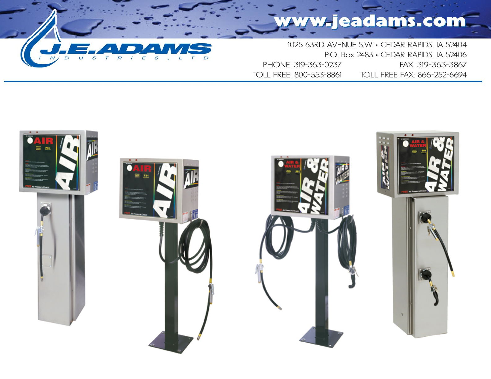
PRODUCT INFORMATION
Please take a moment to fill out the information below in order to aid us with any future sales or
service inquiries. Model number and serial number information can be found on the serial tag
located inside the control box and/or on the lower exterior of the can. Key number can be found
on the tag that comes attached to the keys. There may be more than one key number depending
on unit.
Please keep this information with your records.
MODEL#:_________________________________________
SERIAL#:_________________________________________
KEY NUMBER(S):_________________________________
DATE PURCHASED:_______________________________
DISTRIBUTOR:___________________________________
J.E. Adams Industries
1025 63rd Ave. S.W.
Cedar Rapids, IA 52404
1-800-553-8861
www.jeadams.com

4
SPECIFICATIONS:
Unit specifications:
Voltage: 120v, 60Hz
Amperage: (1) 20 amp service for air/water or air only.
(1)10 amp service for air/water or air only “Only on units which in include
the letters TT OR G in model #. (Example 8670-2TTA or 8670-2GA). Do
not attempt to hook other models up in this fashion. Instant failure will
occur.
Weight: 155-175 lbs with pallet attached
____________________________________________________________________________________
Air specifications:
Compressor: Dependant on Model # ordered
Thomas 120vac@60hz, ¾ hp twin head
Thomas 120vac@60hz, ¾ hp- non twin head
Devilbiss 120vac@60hz, 1 ½ hp
Gast 120vac@60hz, ¾ hp- twin head
Timer: SSAC and Infitec ASCR54
__________________________________________________________________________________________________
Water specifications:
Solenoid: 120vac@60hz
__________________________________________________________________________________________________
NOTE: “UNIT INTENDED FOR COMMECIAL USE ONLY”
Duty cycle: 4 minutes run time- max
4minutesofftime

5
IMPORTANT SAFETY INSTRUCTIONS
When using an electrical appliance, basic precautions should always be followed, including the following:
READ ALL INSTRUCTIONS BEFORE USING (THIS APPLIANCE)
WARNING – To reduce the risk of fire, electric shock, or injury:
Use only as described in manual. Use only manufactures recommended attachments.
Do not allow to be used as a toy. Close attention is necessary when used by or near children.
Keep hair, loose clothing, fingers, and all parts of body away from openings and moving parts.
Never use air nozzle for anything other than for its intended use.
SAVE THESE INSTRUCTIONS
Installation Instructions:
Determine location to mount unit (“DANGER” “THIS EQUIPMENT INCORPORATES PARTS SUCH AS
SWITCHES, MOTORS, OR THE LIKE THAT TEND TO PRODUCE ARCS OR SPARKS THAT CAN CAUSE AN
EXPLOSION. WHEN LOCATED IN GASOLINE-DISPENSING AND SERVICE STATIONS INSTALL AND USE
AT LEAST 20 FEET (6 M) HORIZONTALLY FROM THE EXTERIOR ENCLOSURE OF ANY DISPENSING PUMP
AND AT LEAST 18 INCHES (450 MM) ABOVE A DRIVEWAY OR GROUND LEVEL.”
Run service to that location
Grounding Instructions: This appliance must be connected to a grounded metal, permanent wiring system; or an
equipment-grounding conductor must be run with the circuit conductors and connected to the equipment-grounding
terminal or lead on the appliance.
See next page for bolt pattern.
6
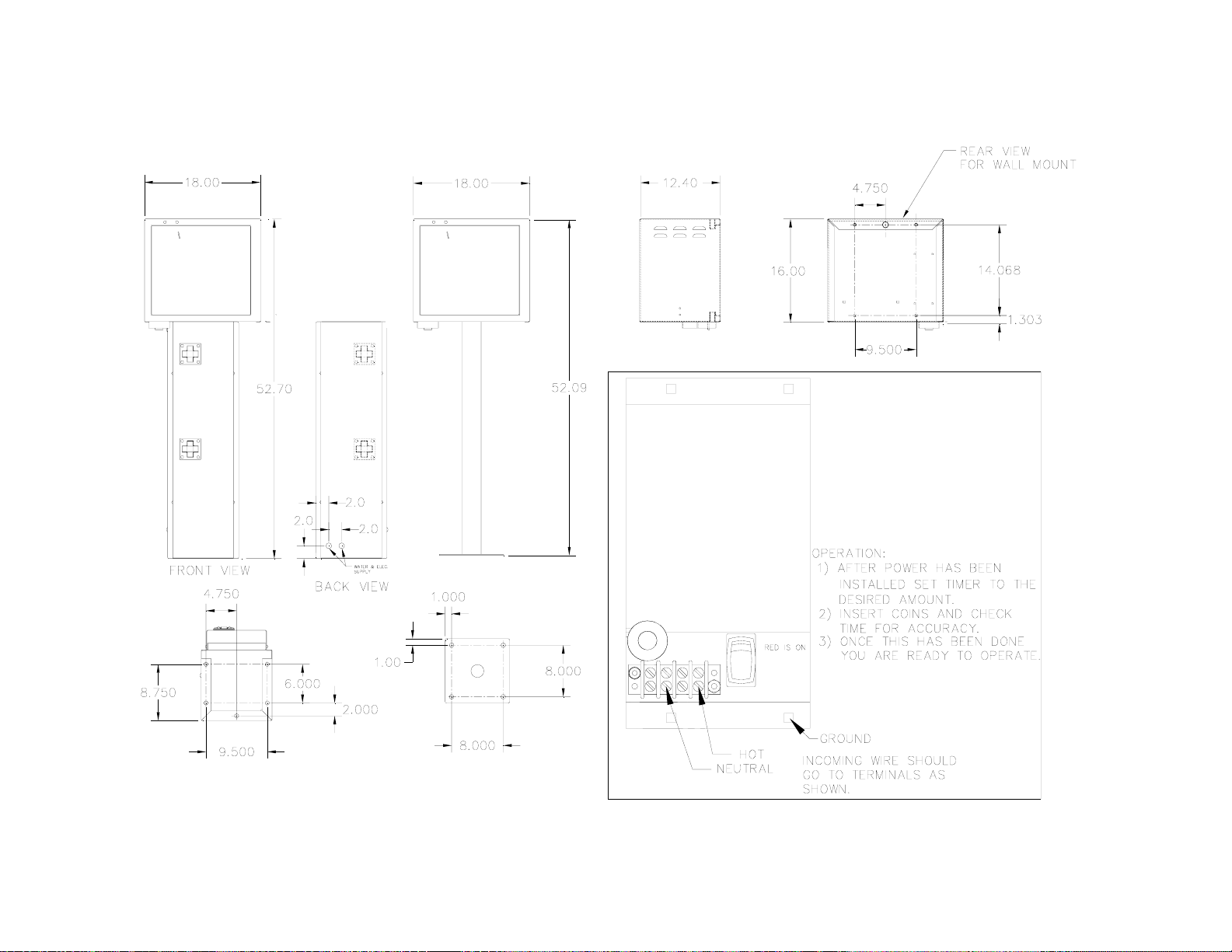
AIR MACHINE MOUNTING DIMENSIONS
7
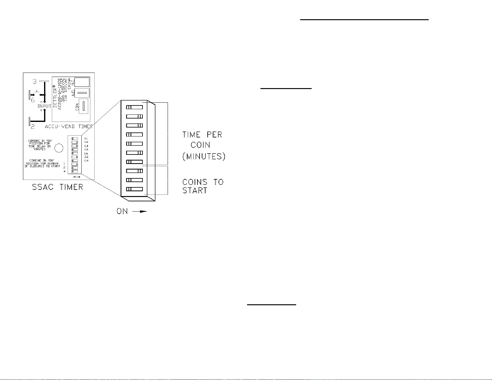
Figure 3: SSAC timer setup
Figure 3 shows an SSAC timer set for 1 coin to start and 3.8
minutes per coin for a total run time of 3.8 minutes (3 minutes
and 48 seconds).
TIMER SETUP – SSAC TIMERS
Note: “AE” and “AN” model SSAC timers are accumulating
timers. During use, timing can be extended proportionately
by adding more coins.
The SSAC timer has two adjustable settings: Time per coin (in
minutes) and number of coins to start.
Time per coin:
Time per coin is the amount of time the unit will run per coin
inserted and can be set from 0.1 minutes (6 seconds) to 12.7
minutes (12 minutes and 42 seconds) in increments of 6 seconds
by turning on the correct switches until their values equal the
desired time.Refer to Tables 2 and 3 (pages 11-12) for standard
timer and coin settings. For custom settings, follow the steps
below:
1. Figure the total time your vac will run (in minutes) and divide
that number by the number of coins to start. This is your
time per coin. Round up or down to the nearest tenth of a
minute.
2. Subtract the largest value switch (initially 6.4) from your time
per coin.
a. If the resulting number is zero, move the switch to
the “on” position and set all remaining un-set switches
in the “off” position. Your timer is now set.
b. If the resulting number is positive, move the switch
into the “on” position. Using the resulting number as
your new time per coin, repeat step 2 with the next
largest switch value.
c. If the resulting number is negative, set the switch in
the “off” position and repeat step 2 using the next
largest switch value.
Coins to start:
Coins to start is the amount of coins needed to activate the
timer and can be set from one to seven coins in increments of
one coin. Refer to Table
2 (page 10) for switch settings
8
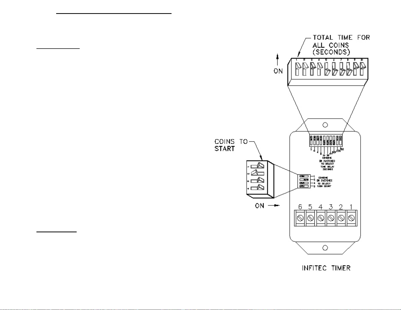
TIMER SETUP – INFITEC TIMERS
The Infitec timer has two adjustable settings: Total run time
(in seconds) and number of coins to start.
Total run time:
Total run time is the amount of time the unit will run
once activated and can be set from 1 second to 1023 seconds
(17 minutes and 3 seconds) in increments of 1 second by
turning on the correct switches until their values equal the
desired time.Refer to Tables 2 and 3 (pages 11-12) for
standard timer and coin settings. For custom settings, follow
the steps below:
1. Figure the total time your vac will run (in seconds).
This is your total run time. Round up or down as
desired.
2. Subtract the largest value switch (initially 512) from
your total run time.
a) If the resulting number is zero, move the
switch to the “on” position and set all remaining
un-set switches in the “off” position. Your timer
is now set.
b) If the resulting number is positive, move the
switch into the “on” position. Using the
resulting number as your new time per coin,
repeat step 2 with the next largest switch value.
c) If the resulting number is negative, set the
switch in the “off” position and repeat step 2
using the next largest switch value.
Coins to start:
Coins to start is the amount of coins needed to activate
the timer and can be set from one to 15 coins in
increments of one coin. Refer to Table 2 (page 10) for
switch settings.
9
5
10
15
20
25
30
35
40
45
50
55
60 (1 min)
70
80
90
100
110
120 (2 min)
130
140
150
160
170
180 (3 min)
190
200
210
220
230
240 (4 min)
250
260
270
280
290
300 (5 min)
1xxxxxx
2xx xx xxxxxxxxxxxxxx
4x xx x x xxx xx xx xx xx xx x
8xx xx xx x x xx x x xx x x xx x
16 xxx xxx xx x x xx xx xx x
32 xxxxxx xxx xxxx xxx xx
64 xxxxxx xxxxxx
128 xxxxxxxxxxxxx
256 xxxxx
512
0.1 (6sec)
0.2 (12 sec)
0.3 (18 sec)
0.4 (24 sec)
0.5 (30 sec)
0.6 (36 sec)
0.7 (42 sec)
0.8 (48 sec)
0.9 (54 sec)
1.0
1.1
1.2
1.3
1.4
1.5
1.6
1.7
1.8
1.9
2.0
2.5
3.0
3.5
4.0
4.5
5.0
5.5
6.0
6.5
7.0
7.5
8.0
8.5
9.0
9.5
10.0
0.1 xxxxxxxxxxxxxxxxxx
0.2 xx xx xx xx xx xx xx xx xx
0.4 xxxx xxxx x x x xx x x xx
0.8 xxxxxxxx xx xx x x xx
1.6 xxxxxxx xxx xxxx
3.2 xxxxxx x
6.4 xxxxxxxx
1
2
3
4
5
6
7
8
9
10
11
12
13
14
15
1xxxxxxxx
2xx xx xx xx
4xxxx xxxx
8xxxxxxxx
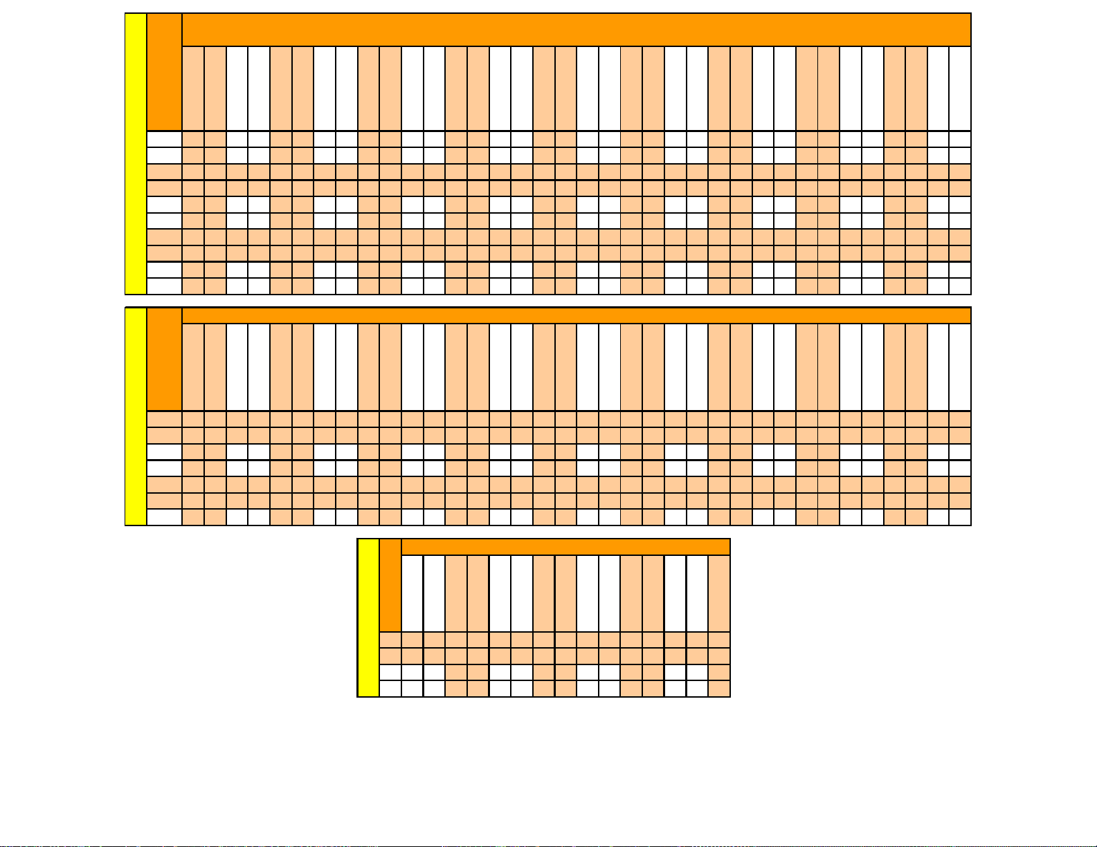
All Timers
Coin Switches
Coins to Start
SSAC Timers
Timer Switches
Time Per Coin (In minutes)
Infitec Timers: Total Run Time (In Seconds)
Infitec and IDX Timers
Timer Switches
IDX Timers: Time Per Coin (In Seconds)
Table 2: Timer Settings Chart
Note: “X” indicates a switch in the “on” position
10
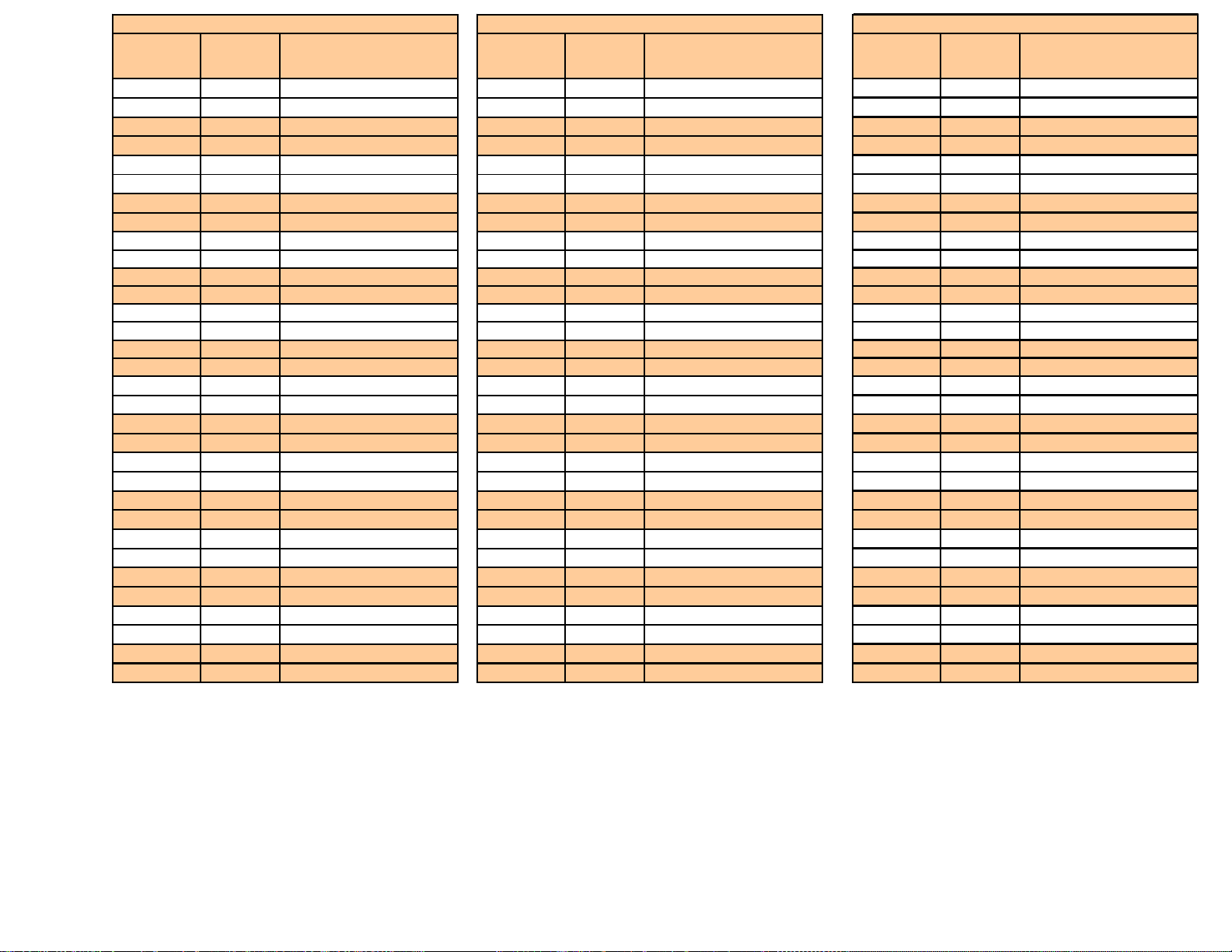
Amount to
Start Total Run
Time Switches in "On"
Position Amount to
Start Total Run
Time Switches in "On"
Position Amount to
Start Total Run
Time Switches in "On"
Position
25¢ 2 MIN 8, 16, 32, 64 25¢ 2 MIN 0.4, 1.6 25¢ 2 MIN 8, 16, 32, 64
25¢ 2-1/2 MIN 2, 4, 16, 128 25¢ 2-1/2 MIN 0.1, 0.8, 1.6 25¢ 2-1/2 MIN 2, 4, 16, 128
25¢ 3 MIN 4, 16, 32, 128 25¢ 3 MIN 0.2, 0.4, 0.8, 1.6 25¢ 3 MIN 4, 16, 32, 128
25¢ 3-1/2 MIN 2, 16, 64, 128 25¢ 3-1/2 MIN 0.1, 0.2, 3.2 25¢ 3-1/2 MIN 2, 16, 64, 128
25¢ 4 MIN 16, 32, 64, 128 25¢ 4 MIN 0.8, 3.2 25¢ 4 MIN 16, 32, 64, 128
25¢ 4-1/2 MIN 2, 4, 8 , 256 25¢ 4-1/2 MIN 0.1, 0.4, 0.8, 3.2 25¢ 4-1/2 MIN 2, 4, 8, 256
25¢ 5 MIN 4, 8, 32, 256 25¢ 5 MIN 0.2, 1.6, 3.2 25¢ 5 MIN 4, 8, 32, 256
25¢ 5-1/2 MIN 2, 8, 64, 256 25¢ 5-1/2 MIN 0.1, 0.2, 0.4, 1.6, 3.2 25¢ 5-1/2 MIN 2, 8, 64, 256
50¢ 2 MIN 4, 8, 16, 32 50¢ 2 MIN 0.2, 0.8 50¢ 2 MIN 8, 16, 32, 64
50¢ 2-1/2 MIN 4, 8, 64 50¢ 2-1/2 MIN *50¢ 2-1/2 MIN 2, 4, 16, 128
50¢ 3 MIN 2, 8, 16, 64 50¢ 3 MIN 0.1, 0.2, 0.4, 0.8 50¢ 3 MIN 4, 16, 32, 128
50¢ 3-1/2 MIN 2, 8, 32, 64 50¢ 3-1/2 MIN *50¢ 3-1/2 MIN 2, 16, 64, 128
50¢ 4 MIN 8, 16, 32, 64 50¢ 4 MIN 0.4, 1.6 50¢ 4 MIN 16, 32, 64, 128
50¢ 4-1/2 MIN 8, 128 50¢ 4-1/2 MIN *50¢ 4-1/2 MIN 2, 4, 8, 256
50¢ 5 MIN 2, 4, 16, 128 50¢ 5 MIN 0.1, 0.8, 1.6 50¢ 5 MIN 4, 8, 32, 256
50¢ 5-1/2 MIN 2, 4, 32, 128 50¢ 5-1/2 MIN *50¢ 5-1/2 MIN 2, 8, 64, 256
75¢ 2 MIN 8, 32 75¢ 2 MIN *75¢ 2 MIN 8, 16, 32, 64
75¢ 2-1/2 MIN 2, 16, 32 75¢ 2-1/2 MIN *75¢ 2-1/2 MIN 2, 4, 16, 128
75¢ 3 MIN 4, 8, 16, 32 75¢ 3 MIN 0.2, 0.8 75¢ 3 MIN 4, 16, 32, 128
75¢ 3-1/2 MIN 2, 4, 64 75¢ 3-1/2 MIN *75¢ 3-1/2 MIN 2, 16, 64, 128
75¢ 4 MIN 16, 64 75¢ 4 MIN *75¢ 4 MIN 16, 32, 64, 128
75¢ 4-1/2 MIN 2, 8, 16, 64 75¢ 4-1/2 MIN *75¢ 4-1/2 MIN 2, 4, 8, 256
75¢ 5 MIN 4, 32, 64 75¢ 5 MIN *75¢ 5 MIN 4, 8, 32, 256
75¢ 5-1/2 MIN 2, 4, 8, 32, 64 75¢ 5-1/2 MIN *75¢ 5-1/2 MIN 2, 8, 64, 256
$1.00 2 MIN 2, 4, 8, 16 $1.00 2 MIN 0.1, 0.4 $1.00 2 MIN 8, 16, 32, 64
$1.00 2-1/2 MIN 2, 4, 32 $1.00 2-1/2 MIN *$1.00 2-1/2 MIN 2, 4, 16, 128
$1.00 3 MIN 4, 8, 32 $1.00 3 MIN *$1.00 3 MIN 4, 16, 32, 128
$1.00 3-1/2 MIN 2, 4, 16, 32 $1.00 3-1/2 MIN *$1.00 3-1/2 MIN 2, 16, 64, 128
$1.00 4 MIN 4, 8, 16, 32 $1.00 4 MIN 0.2, 0.8 $1.00 4 MIN 16, 32, 64, 128
$1.00 4-1/2 MIN 4, 64 $1.00 4-1/2 MIN *$1.00 4-1/2 MIN 2, 4, 8, 256
$1.00 5 MIN 4, 8, 64 $1.00 5 MIN *$1.00 5 MIN 4, 8, 32, 256
$1.00 5-1/2 MIN 4, 16, 64 $1.00 5-1/2 MIN *$1.00 5-1/2 MIN 2, 8, 64, 256
IDX TIMER SETTINGS SSAC TIMER SETTINGS INFITEC TIMER SETTINGS
Table 3: Typical Timer Settings
Note: “*” denotes a configuration that is not possible with this timer. See Table 2 for the closest approximation to
this time

11
MAINTENANCE
Check air nozzle for signs of wear and abuse. Replace as needed.
Clean air cabinet as needed with a non abrasive stainless steel cleaner.
Examine air hose for cuts or wear and replace as needed.
Every month remove filter from compressor and clean.
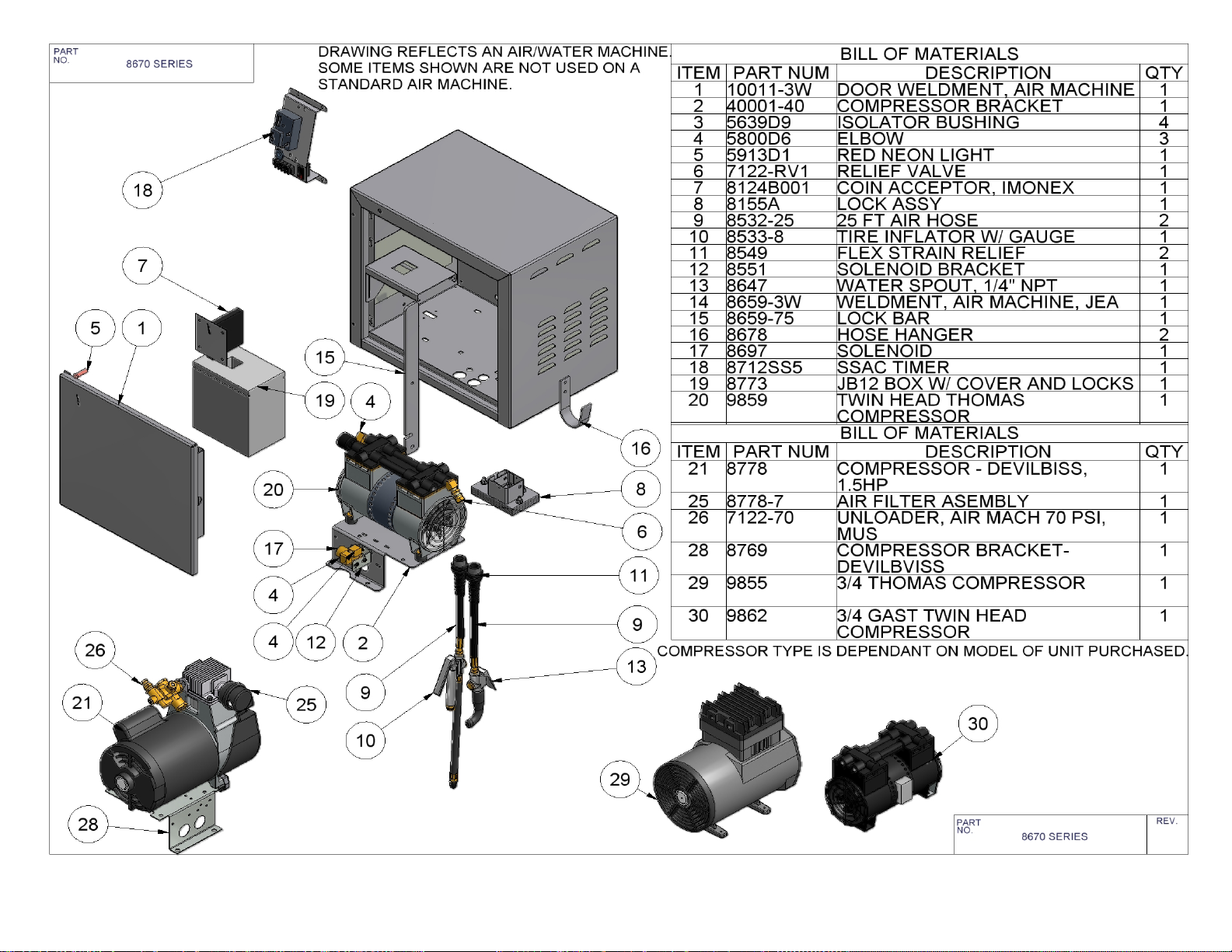
12

13
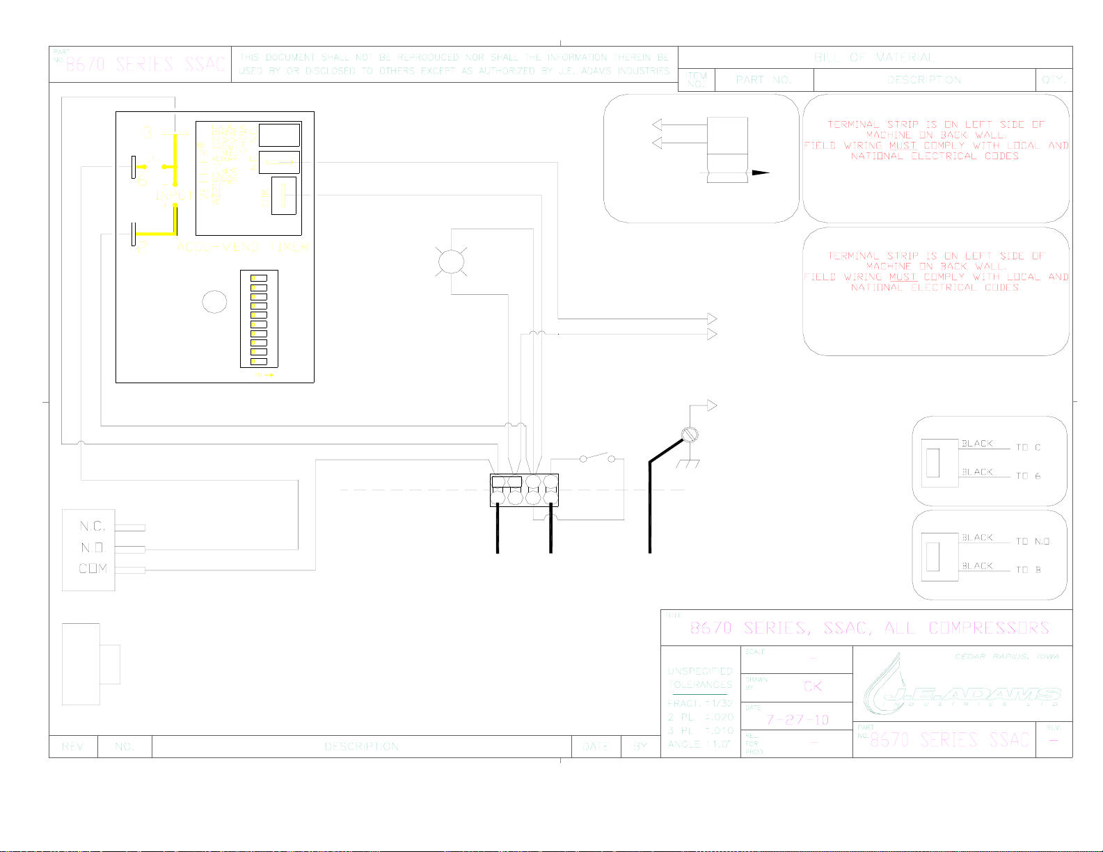
14
BLK
ALL COMPRESSORS
(GREEN)
R
POWER ON
18 GA WHITE
THOMAS (BROWN)
GAST (BLACK)
DEVILBISS (BLACK)
18 GA BLACK
18 GA BLUE
18 GA BLUE
12 GA BLACK
18GA BLACK
FACTORY WIRING
FIELD WIRING
120 VAC (NEUT)
OPTIONAL CYCLE COUNTER
120VAC, PART # 8641
OPTIONAL COIN COUNTER
120VAC, PART # 8641-1
!! IMPORTANT !!
*20AMP SERVICE IS
REQUIRED
FOR DEVILBISS UNITS*
18GA BLACK
!! IMPORTANT !!
*10AMP SERVICE IS
REQUIRED FOR TWIN
THOMAS & GAST UNITS*
THOMAS (BLUE)
GAST (WHITE)
DEVILBISS (WHITE)
TO
COMPRESSOR
TO
COMPRESSOR
120 VAC (HOT)
120 VAC (GROUND)
8124B001
8712SS5
8673-9
5914
BC
AD
GFHE
WATER SOLENOID
BLACK
BLACK
TO NO
TO B
ONLY USED WITH UNITS
WITH WATER FEATURE
8697
8726
SWITCH CONNECTIONS ARE THE BLUE WIRES CURRENTLY
SHOWN GOING TO THE COIN ACCEPTOR. WHEN SWITCH IS
USED COIN ACCEPTOR IS NOT USED.

15
BLK
ALL COMPRESSORS
(GREEN)
R
POWER ON
18 GA WHITE
THOMAS (BROWN)
GAST (BLACK)
DEVILBISS (BLACK)
18 GA BLACK
18 GA BLUE
18 GA BLUE
18GA BLACK
FACTORY WIRING
FIELD WIRING
120 VAC (NEUT)
OPTIONAL CYCLE COUNTER
120VAC, PART # 8641
OPTIONAL COIN COUNTER
120VAC, PART # 8641-1
!! IMPORTANT !!
*20AMP SERVICE IS
REQUIRED
FOR DEVILBISS UNITS*
18GA BLACK
!! IMPORTANT !!
*10AMP SERVICE IS
REQUIRED FOR TWIN
THOMAS & GAST UNITS*
THOMAS (BLUE)
GAST (WHITE)
DEVILBISS (WHITE)
TO
COMPRESSOR
TO
COMPRESSOR
120 VAC (HOT)
120 VAC (GROUND)
8124B001
8673-9
5914
BC
AD
GFHE
WATER SOLENOID
BLACK
BLACK
TO 2
TO 3
ONLY USED WITH UNITS
WITH WATER FEATURE
8697
8726
SWITCH CONNECTIONS ARE THE BLUE WIRES CURRENTLY
SHOWN GOING TO THE COIN ACCEPTOR. WHEN SWITCH IS
USED COIN ACCEPTOR IS NOT USED.
8712iD

16
TROUBLESHOOTING INFORMATION:
STARTS BUT NO PRESSURE
SYSTEM LEAKING
CHUCK IS CLOGGED
UNLOADER
PARTS DAMAGED OR WORN
OUT.
CHECK AIR HOSE FOR LEAKS
AND AIR CHUCK. ALSO CHECK
FOR LEAKS AROUND
COMPRESSOR.
CHECK AIR CHUCK TO MAKE
SURE NO DEBRIS IS AIR PATH.
ALSO CHECK ORING AROUND
AIR CHUCK, IS IT BLOCKING
THE AIR PATH.
IS IT UNLOADING ALL THE
TIME?
SLEEVE IN COMPRESSOR MAY
BE PITTED OR SCRATCHED
UP. PISTON ORING MAY BE
WORN OR DAMAGED. DEBRIS
IN VALVE PLATE OPENING IS
NOT ALLOWING IT TO SHUT.
REPAIR KIT MAY BE NEEDED.
WARNING
Disconnect Power before
Servicing
WARNING
Disconnect Power before
Servicing
Table of contents
Popular Air Compressor manuals by other brands


Scheppach
Scheppach HC24 Translation of original instruction manual

AREBOS
AREBOS AR-HE-LK110024OF user manual

Ozito
Ozito PXC PXOFCS-636 instruction manual

KNF
KNF NPK 03 KV DC-M Operating and installation instructions

Trane
Trane R410a installation guide

Ingersoll-Rand
Ingersoll-Rand P101 Operation and maintenance manual