J.E. Adams Aqua Breeze 6700D User manual

6700D Fan & Pump Station:
> ¼ HP motor – 120 Volts – 3.5 Amps 60hz, 1075rpm (FAN).
> 1.5 HP motor – 120 Volts – 14.4/7.2amps, 60hz, 1725rpm (PUMP)
> 17.9 Amps total – Dedicated 20A (pump) & 15A (fan) power supplies needed.
> 2.2 gpm pump @ 1725rpm
> Motor/pump combination supports 80 nozzles.
> Dual filtration 5 & 10 micron filter housing uses standard garden hose water
connection for easy hook up.

Aqua Breeze™ Instructions Mobile II Cooling Fan
Initial Setup of the Unit:
1) After assembly: Remove the fan sub-assembly and hardware from the shipping carton.
a) The fan may be tilted to four separate positions by pulling the pin on the side of
the fan mount, tilting the fan to the required position and inserting the hitch pin.
b) DO NOT ATTEMPT TO ADJUST FAN TILT WHILE THE FAN IS RUNNING.
SERIOUS INJURY MAY OCCUR.
c) Connect the fan cord, finger tight, to the fan outlet near the top of the column.
2) Connect your water inlet hose (Not provided by J.E. ADAMS Industries, Ltd. to a
potable water source capable of delivering at least 1/2 gallon per minute of water at a
pressure not less than 20 Psig and not more than 125 Psig.
3) Important: The water source must be free of pressure surges caused by other
equipment. Pressure surges may cause air to become entrained in the water supply.
Running the pump under a dry condition will void the warranty on the pump
assembly.
4) Purchase an RV water pressure regulator locally to reduce the inlet water pressure to
50-55 Psig if your potable water pressure exceeds 125 Psig and install it at the
cooling fan water inlet.
5) The aqua-breeze-cooling fan is now ready for operation.
Operation of Unit:
1) Select an unobstructed location.
2) Connect the hose to the closed inlet shut-off valve and turn the source water on full
open.
3) Open the inlet shut-off valve slightly and eliminate all air from the hose. Close the
valve once the air is eliminated. Connect the inlet shut-off valve to the cooling fan
water inlet and open the valve
4) Select fan oscillation: 90o, 45o or 0o before operating the unit.
5) If the fan should be oscillating and is not oscillating, disconnect the electrical power
and hand tighten knob on top of the fan motor. Turn clockwise to 100 inch pounds. If
the unit still will not oscillate after restarting, the oscillator mechanism may need to be
replaced.
6) DO NOT ATTEMPT TO ADJUST FAN TILT WHILE THE FAN IS RUNNING.
SERIOUS INJURY MAY OCCUR.
7) The fan may be tilted in four positions by pulling the pin on the side of the fan mount,
tilting the fan to the required position and reinserting the pin.

8) Connect the power cord to 120V electrical power.
9) It is highly recommended that the power source be protected by a Ground Fault
Circuit Interrupter type circuit breaker.
10) When allowed by local authorities, you may extend your fan location, up to 100 feet,
using an appropriate gauged electrical cord.
11)Turn the fan “on.”
12)Turn the misting pump “on” to produce the “flash-cooling” effect.
Maintenance:
DISCONNECT ALL ELECTRICAL POWER AND THE SOURCE WATER HOSE PRIOR TO PERFORMING
ANY MAINTENANCE.
1) FAN UNIT MAINTENANCE:
a) Periodically, the fan unit shroud and guards should be cleaned with a mild
detergent and wiped completely dry.
i) Periodically, check the misting nozzles performance.
ii) If the misting cone is deformed or absent, clean the nozzles, using 1 cup of
"hot" water, 1 cup of 5% vinegar.
iii) Soak nozzles for 10 minutes.
iv) Install on unit and run pump immediately to flush out.
v) Compressed air may also work as an alternative.
vi) Replace the nozzles if necessary.
b) Periodically, check the electrical power cord for abrasions, cracking or other wear.
Replace as necessary.
c) Periodically, check the high pressure water line for leaks, or other signs of wear.
Replace as necessary.
d) When the pump runs intermittently, the particulate filter element needs to be
replaced. In any event, replace the particulate filter element seasonally.
e) The external Water Conditioner cartridge should be replaced whenever the
misting nozzles show signs of “liming up,” or seasonally, whichever comes first.
2) PUMP UNIT MAINTENANCE:
a) The internal Sediment filter cartridge should be replaced if the misting pump runs
intermittently, or seasonally, whichever comes first.
b) The water pump oil should be replaced after the first 50 hours of operational time.
c) Subsequent oil changes should occur after every 500 hours of operational time or
seasonally, whichever comes first.
d) Use 10 oz. CAT pump oil per change. J.E. ADAMS Industries, Ltd. Pn 6611B013.
Do not fill above the center of the oil viewing glass.
e) Install the base cover prior to using the unit.
RECONNECT THE WATER HOSE AND THE ELECTRICAL POWER CORD WHEN DESIRED.

Storage Procedure:
1) Disconnect the water hose from the unit inlet fitting.
2) Install the winterization adapter, J.E. Adams Pn 6687T001, on the water hose inlet
fitting.
3) Connect a compressed air source to the winterization adapter. Do not use
compressed air at more than 100 Psig.
4) DO NOT LEAVE THE UNIT UNATTENDED DURING THE FOLLOWING STEPS:
a) Switch the Pump “ON” briefly to clear the system of water. The system will be
clear when the column connector discharges air only from the unit.
b) Stop the pump immediately when the water has been eliminated. DO NOT RUN
THE UNIT WITHOUT WATER.
c) Plug all water fitting openings and protect the nozzle fittings from damage.
d) Wipe down the entire unit to remove excess water droplets.
5) Disconnect the electrical power cord and store on the power cord take-up located on
the rear of the column.
6) Store the unit in a clean, secure location.

Troubleshooting:
Problem Solution
The unit fails to operate Verify that the unit is plugged in and that electrical power is available.
The unit fails to produce mist.
Verify that the source water hose is connected and that inlet valve and the hose bib
are both open and that water flow is adequate.
The source water pressure should be between 20 and 125 Psig. The flow capacity at
the unit should be at least 1/2 gallon per minute.
One or more nozzles fail to produce mist while
others do.
The nozzles not producing mist may be plugged and should be cleaned or replaced.
The external Water Conditioner cartridge or the internal filter element needs to be
replaced.
The fan runs poorly, or extremely hot.
Check the electrical power available at the unit.
120 Volt units will operate correctly with electrical voltage readings from
108 Volts to 132 Volts AC.
Class “B” motors are designed to operate at a “motor winding temperature” that does
not exceed 266oF. The fan motor is protected by an automatic reset thermal overload
device.
The fan operates intermittently without human
intervention. The thermal overload device protecting the fan motor is doing its job, (protecting the
motor from overheating).
The misting pump does not run or runs
intermittently.
Check the electrical power available at the unit. (See above)
Check the water source valves. If any have been closed, the pump will stop
automatically and the safety pressure switch will be “ON.”
It is normal for the pump motor to “feel hot.” If the pump motor is not running
verify that the safety pressure switch light is “OFF.”
This will be likely to happen to a pump motor if the discharge pressure has been set
too high. Set the pressure regulator to 700 Psig maximum. In any event, do not
exceed the FLA (Full Load Amps) listed on the motor nameplate. Use an ammeter to
verify the setting.
The pump motor will run intermittently when either or both the filter and water
conditioner must be replaced. When the filter or water conditioner become plugged
due to sediment accumulation, the pressure switch will stop the pump motor. When
the pressure builds up again, the pump will run for a short period of time. Replace
the water conditioner and the filter cartridge.
If this becomes a common occurrence, the motor may have developed a problem
requiring replacement.
The unit leaks water from the misting pump
compartment.
Disconnect the unit electrical power. Remove the pump compartment cover and
inspect for leaks.
The drain valve will release a small volume of water each time the pump is stopped.
This is for the purpose of draining water from the misting nozzle ring.
A thermal relief valve will discharge water when the water temperature exceeds 140o
F. This protects the pump from heat damage and is normal.
Repair any other leaks as needed.
For other problems please contact your dealer, or J.E. ADAMS Industries at
(800) 553-8861
Table of contents
Popular Fan manuals by other brands
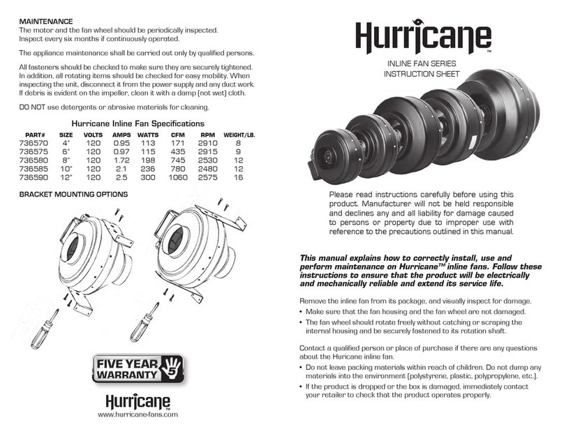
Hurricane
Hurricane INLINE Series instruction sheet
Magnamed
Magnamed Fleximag Operation manual
Bimar
Bimar VM41 instruction manual
Zehnder Rittling
Zehnder Rittling comfocool Manual for the user
Helios
Helios AIR1-CO DX Installation and operating instructions

Westinghouse
Westinghouse ETL-ES-Quince LED-WH19 owner's manual

