manuals.online logo
Brands
  1. Home
  2. •
  3. Brands
  4. •
  5. J-Systems
  6. •
  7. Camera Accessories
  8. •
  9. J-Systems RUG-ID User manual

J-Systems RUG-ID User manual

Page: 1
RUG-ID Tripod
User Manual
Ver. 1.00 July 2020
J-Systems, Inc.
1S 678 School St.
Lombard, IL 60148
Tele: 630-627-3458
Fax: 630-620-0960
E-Mail: info@J-Systems.com
Page: 2
Table of Contents
1.0 System Overview··················································································· 3
1.1 Part Descriptions, ID Photos, and Quantities ·········································· 3
1.2 Tripod Erection ················································································ 4
Photos ……………………………………………………………………………….. 5
1.3 CAUTIONS ····················································································· 5
2.0 Revision History………………………………………………………………...………… 8
DISCLAIMER
J-Systems, Inc. makes no warranties, either express or implied, regarding the RUG-ID Tripod, its
merchantability or its fitness for any particular purpose.
Further, in no event shall J-Systems, Inc. be liable for indirect, incidental, special, exemplary, punitive, or
consequential damages of any nature including, but not limited to, loss of profits, revenue, production,
use, or business interruption arising out of or in connection with the use or performance of any
J-Systems, Inc. product, whether based on contract or tort, including negligence, or any other legal
theory, even if J-Systems, Inc. has been advised of the possibility of such damages.
J-Systems, Inc. total aggregate liability for damages of any nature, regardless of form of action, shall in
no event exceed the amount paid by you to J-Systems, Inc. for the product upon which liability is based.
Page: 3
1.0 - SYSTEM OVERVIEW
The RUG-ID Tripod is a rugged, portable, uniquely designed Aluminum mast system that can be
assembled without any tools and offers 4-points of contact with the terrain for maximum
stability. It has been designed to carry a small PTZ camera, digital camera, LED spot lights, or
antennas at the top with or without the need for guy ropes.
1.1 Part Descriptions, ID Photos, and Quantities
The 9 Ft. tripod is comprised of the following components:
(6) 35” 1.5”OD, 1.25”ID Thick Walled Mast Tubes (6061/T6 Alum, Black Anodized)
(3) 17” 1.5”OD, 1.25”ID Thick Walled Mast Tubes (6061/T6 Alum, Black Anodized)
(3) Extension Legs (6061/T6 Alum)
(1) Center Weldment (6061/T6 Alum, Black Anodized)
(8) Interconnecting Pins (6061/T6 Alum)
(1) Base Ring (6061/T6 Alum, Black Anodized)
(1) Top Mounting Plate (6061/T6 Alum, Black Anodized—Custom design optional)
(1) Cad Plated 12” Steel Screw-In-Earth Stake
Top & Base Ring
Center w/ Pins
(upside down)
Adj Foot Assembly
w/ Jam Nut
Adj Foot Into 17” Mast
NOTE:
Tripod Can
collapse down to
35” in length
Center Suppoprt
Page: 4
1.2 Tripod Erection (see next pages for photos)
Erecting the tripod is relatively simple but please follow these steps for the easiest assembly.
CAUTION: Read 1.3 Cautions on Pg 7
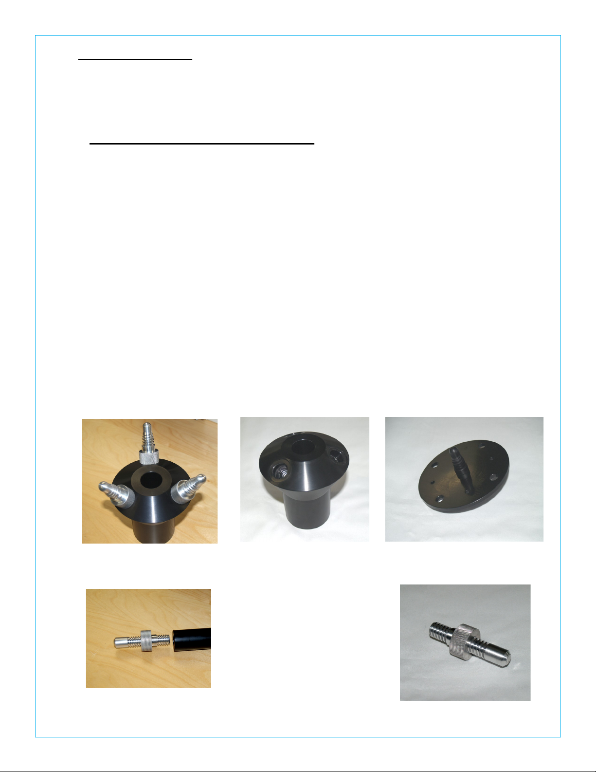
NOTE: When using the specially designed precision threaded pins, please align the pin
to the tube thread and lightly screw the pin into place until the pin’s shoulder
is fully seated inside the tube counterbore area. DO NOT force the threads,
if jammed, simply backoff and realign the mating parts and try again.
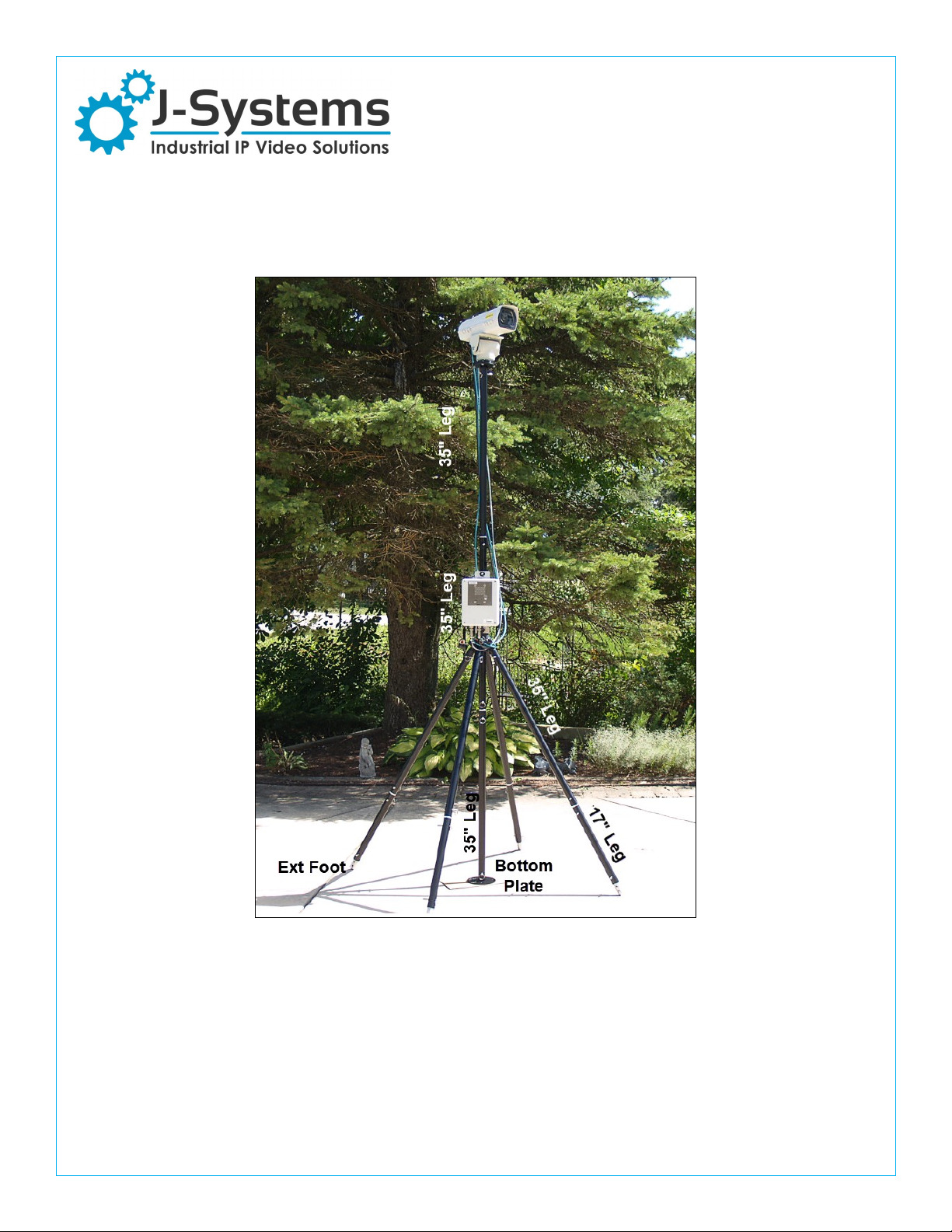
Step 1 — assemble three 35” legs to the Center Support using (3) pins. Now, screw (3) 17” legs into
the pins already installed in each of the longer legs. The Adjustable Feet and Jam Nut are already
attached to the far end of the 17” legs sections. Now stand the tripod up on its legs.
Step 2— insert the small bubble level (Opt) into the Center Support top hole and adjust the
Adjustable Feet to obtain the best level possible.
Step 3— attach (2) 35” mast sections together. Slip these down through the center hole of the Center
Section. If you plan to use guy ropes, these should now be attached to the top 6” round plate in the
(3) large holes.
Step 4 — if using a JPTH-13MPoE, now secure a 6” dia plate to the black base ring of the Pan/Tilt
Head Camera Enclosure assembly using (4) SS Thumb Screws. Next screw the Pan/Tilt Head and
Camera Enclosure into the top of the upper mast section.
Step 5 — lift the (2) mast sections with Pan/Tilt Head and Camera Enclosure up high enough in the
Center Support to insert the final 35” leg with it’s 6” round plate as the bottom mast section. This
may require two people to accomplish, but can be done by one person. If you are using an extra
mast section to go to 12 ft, this same technique can be used (insert the last mast section from the
bottom).
Step 6 — rotate the center mast until the camera is pointed to the approximate center of the viewing
area. Then stake the bottom 6” round plate into the ground using a supplied stake (just one is
needed). If you have used the guy ropes, they must also be staked into the ground. Be sure to drive
the stakes for the guy ropes into the ground at a 45 deg angle so they do not pull out due to the guy
rope tension.
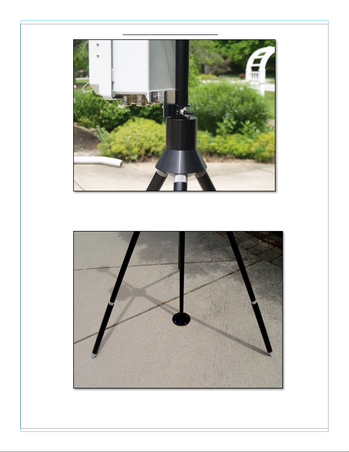
Attach Electronics Enclosure to Tripod Mast
If you have an electronics enclosure, secure it to the mast using the two mast clamps with a single
bolt, then mount the enclosure with SS brackets just above the tripod Center Support. The enclosure
should face the same direction as Camera Enclosure for proper cable management.
Attach Cables
Now attach all related cable from the pan / tilt head and camera to your electronics enclosure.
Option leg clamps can be purchased to further secure the Tripod to the ground using added stakes ,
rocks or other weights.
Page: 5
Tripod Components / Assembly
Top / Bottom 6” Dia Ring
Center Support w/ Pins Inserted
Adjustable Foot w/ Jam Nut
screws Into 17” Long 1.5”
OD Tube
Precision Threaded
Pin Screwed Into 35”
Long 1.25” OD Tube
Precision Threaded
Pin
Bubble Level (Opt)
in Center Support Hole
Page: 6
Tripod Components / Assembly
Adj Foot w/ Jam Nut Screws—Shows Bottom Plate
Which Needs 1-Stake to Hold It In Place
Lower Mounting Bracket for Electronics Enclosure
Right on Top of The Center Suppoprt
Page: 7
1.3 CAUTIONS - READ CAREFULLY
The RUG-ID Tripod as supplied is designed to be used as shown on the cover of this
document. All three legs must be on the ground and the center mast section must also be
resting on the ground via the bottom base plate. This results in an approximate 9 ft height, 4-
legged, very stable support.
Do Use Extreme Caution to prevent any part of the TEMS assembly from coming in
contact with live AC power lines. ALWAYS LOOK UP !!! Coming in contact with a power
line can result in your death.
Do Not place more than 15lbs of weight on top of the mast. Make sure the mechanical
load on top of the mast is centered and as balanced as possible.
Do stake the Base Ring where the mast resets on the ground using the supplied 12” long
screw style stake. Adding additional weights to the top of the Base Ring is also a good
idea; rocks, stones etc.
Do use guy ropes if you are located in a windy area. If using a 12 ft version of the TEMS,
always use guy ropes and stakes (Opt).
Do not place the tripod in a location where, if it were to blow over, it would hit a human or
personal property.
Page: 8
Page: 9
2.0 REVISION HISTORY:
9-17-2019 Original Release Date

Popular Camera Accessories manuals by other brands

Pentax Bulk Film Magazine LX manual

Pentax

Pentax Bulk Film Magazine LX manual

Varta Professional Deep Cycle AGM instruction manual

Varta

Varta Professional Deep Cycle AGM instruction manual

NOVOFLEX VR-System III manual

NOVOFLEX

NOVOFLEX VR-System III manual

Nauticam 17909 instruction manual

Nauticam

Nauticam 17909 instruction manual

PROAIM Victor Pro Assembly manual

PROAIM

PROAIM Victor Pro Assembly manual

Panasonic HHR370AH Specifications

Panasonic

Panasonic HHR370AH Specifications

Hasselblad Proshade 6093T instruction manual

Hasselblad

Hasselblad Proshade 6093T instruction manual

Bebob V150 user manual

Bebob

Bebob V150 user manual

Nauticam NA-GX9 instruction manual

Nauticam

Nauticam NA-GX9 instruction manual

Nikon DK-17M manual

Nikon

Nikon DK-17M manual

Broncolor Mobil A2R operating instructions

Broncolor

Broncolor Mobil A2R operating instructions

D-Link DCS-50 user manual

D-Link

D-Link DCS-50 user manual

Mamiya M645 Super instructions

Mamiya

Mamiya M645 Super instructions

Nauticam 86221 instruction manual

Nauticam

Nauticam 86221 instruction manual

Pentax Auto Extension Tube Set K manual

Pentax

Pentax Auto Extension Tube Set K manual

VADDIO WALLVIEW DVI/HDMI HD-20 Installation and user guide

VADDIO

VADDIO WALLVIEW DVI/HDMI HD-20 Installation and user guide

Sunpak FL-VL specification

Sunpak

Sunpak FL-VL specification

Glidecam X-20 Set up and operation guide

Glidecam

Glidecam X-20 Set up and operation guide

manuals.online logo
manuals.online logoBrands
  • About & Mission
  • Contact us
  • Privacy Policy
  • Terms and Conditions

Copyright 2025 Manuals.Online. All Rights Reserved.