J.W. Davis DIN-100AT User manual

The Mark of the Professional...
NEW TECHNOLOGY OLD RELIABILITY
J.W. Davis & Company •3030 Canton Street • P.O. Box 710219 • Dallas, Texas 75371-0219
Sales 800-527-5705 • Fax 800-388-9106 • Corp 214-651-7341 • Fax 214-939-0328 • www.jwd.com • [email protected]
JWD MODEL DIN-100AT IN-WALL SPEAKER SYSTEM
INSTALLATION INSTRUCTIONS
The Model DIN-100AT is a two-way speaker system designed to be installed flush in walls or ceilings where
foreground music and voice reproduction is desired. The pivoting tweeter allows the directional high fre-
quencies to be pointed to the primary listening area for optimum sound reproduction. It may be used in
monaural 70-volt installations as well as 8-ohm stereo installations (See “Stereo Installation” below). Its
construction provides quick, simple installation as is, or may be painted to blend with any wall or ceiling decor.
Speaker Placement
Higher frequencies are more directional than lower frequencies as shown by the darker area in Figure 1.
Consequently, the sound level of the higher frequencies will be greater when the listener is directly in front
(“on axis”) of the sound source. As the position of the listener moves off axis to either side, the sound level
of the higher frequencies decrease. To compensate for this factor, the high frequency
tweeter of the DIN-100AT can be adjusted toward the primary listening area to provide best
frequency reception.
Keeping the “on-axis” concept in mind, the ideal height of the speakers should be the
listerners’ heads. For stereo, the primary listener’s heads also should be the point of a
triangle that is equal distance between the listener and the two speakers. Where this is
not practical, rotation of the pivoting tweeter should be used to direct the higher frequen-
cies in this triangular pattern. A ±3dB switch located below the tweeter also is available to
further enhance the higher frequencies if desired.
Other suggestions include:
Figure 1
A minimum mounting depth of 3¹⁄₂" measured from the face of the wall or ceiling is needed in order to
fit properly.
6.
A thickness of ³⁄₈" to 1³⁄₈" for wall and ceiling can be accomodated.
5.
Provide at least 2" clearance between cutout and any studs or joist for mounting bracket and hard-
ware to work properly.
4.
Avoid existing electrical wires or pipes.
3.
Avoid objects that may impede the sound path between speakers and listeners.
2.
Avoid mounting speakers near a color TV set. A minimum distance of 12" from the color TV or
monitor is required, or picture distortion will occur. Also keep away from audio or video tapes.
1.
090717138

NEW TECHNOLOGY OLD RELIABILITY
J.W. Davis & Company •3030 Canton Street • P.O. Box 710219 • Dallas, Texas 75371-0219
Sales 800-527-5705 • Fax 800-388-9106 • Corp 214-651-7341 • Fax 214-939-0328 • www.jwd.com • [email protected]
The Mark of the Professional...
Installation Guides
Use INSIDE diminisions of enclosed template to mark the cutout
for the speaker. (Tip: Check top of the cutout with a carpenter’s
level to ensure correct vertical alignment.)
Carefully remove grille using small flat-blade screwdriver to slowly
pry up one corner to access the mouting screws.
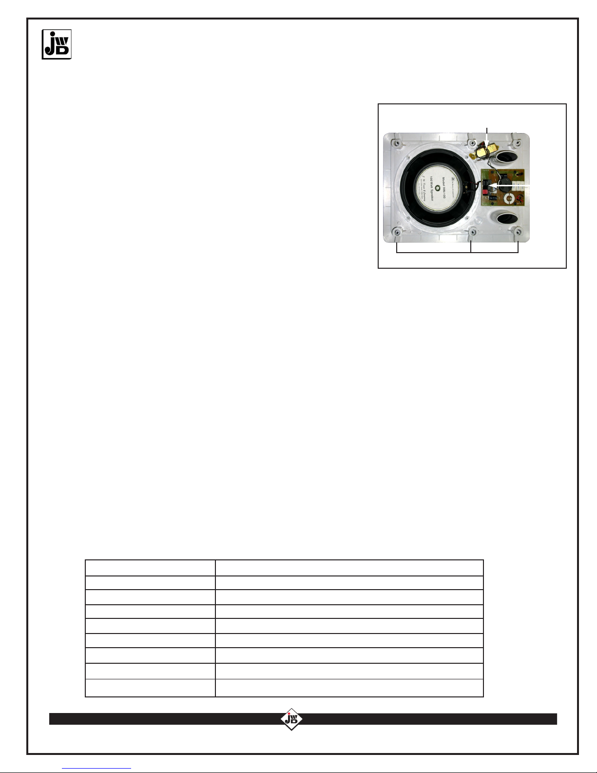
Connect incoming 70 Volt line to the spring-clip terminal, taking
care to maintain correct polarity. (Red 70V, Black Com).
Turn all 6 rotating wall clamps inward and put speaker in cutout
space.
Using phillips screwdriver, tighten the mounting screws. The wall
clamps will rotate as the screws are tightened. (Caution: Too
much force will cause the frame to warp and will damage the
speaker system.)
Stereo Installation
To change the speaker to an 8-ohm impedance for stereo, cut the white & black transformer leads, making sure
to leave enough wire to attach back together if needed. Strip wire leads going to crossover board about ¹⁄₄” and,
using wire nuts, connect the white wire to positive and black to negative. The transformer can remain in the
cabinet without affecting the speaker operation.
Painting the Speaker System
The front of the DIN-100AT speaker may be painted to blend with any decor. For best results, these procedures
should be followed:
Use an aerosol spray paint containing a nitrocellulose lacquer for best adhesion. If using the same paint as
being used for existing walls or ceilings, the grilles should first be spayed with a suitable primer of nitrocellu-
lose material then painted with either an enamel or latex paint
2. Before painting plastic frame and grille, very lightly sand with fine sandpaper
3. Remove grille from frame and spray paint with aerosol paint, taking care to not to overpaint or
overbrush which will fill holes and limit the speaker’s performance
4. Before painting the plastic frame, cover the speakers in the cabinet
TECHNICAL SPECIFICATIONS
System
Power Handling
Frequency Response
Tweeter
Sensitivity
Woofer
Crossover
Dimensions
Adjust the direction of the tweeter toward the primary listening area.
Ported Two-Way In-Wall/Ceiling Speaker System
10¹⁄₄" W x 14⁵⁄₁₆" H x 3¹⁄₂" D
Weight 4 lbs. 12 oz.
45Hz-20kHz ±5dB
1.75" Pivoting with ±3dB Switch
93dB 1w/1m
Two Way
8" Polypropylene, 20 oz. Magnet
Transformer
Rotating wall clamps
DIN-100AT Back View
1.
1.
2.
3.
4.
5.
6.
Spring
clip
terminal
Table of contents
Other J.W. Davis Speakers System manuals