Jabiru 2200 User manual

INSTALLATION MANUAL
FOR 4th GENERATION
JABIRU 2200 and 3300 AIRCRAFT ENGINES
DOCUMENT No. JEM0008-1
This Manual is a guide to correctly install the Jabiru 2200 engine into an airframe.
If you have any questions or doubts about the contents, please contact Jabiru Aircraft P/L.
Applicable to Jabiru Generation 4 2200 from S/No. 22A3936 and 3300 engines from
S/No. 33A2974

Jabiru Aircraft Pty Ltd
Installation Manual
Gen 4 2200 and 3300 engines
ISSUE
1
Dated : Aug 2021
Page: 2 of 55
1.1 Table of Figures .......................................................................................................................3
1.2 List of Effective Pages..............................................................................................................4
1Engine Information .........................................................................................................5
2Controls..........................................................................................................................7
2.1 Throttle and Choke...................................................................................................................7
2.2 Ignition and Starter Systems....................................................................................................9
3Engine Crankcase Breather, Catch Bottle and Dipstick................................................10
4Electrical Equipment.....................................................................................................11
4.1 Alternator................................................................................................................................11
4.2 Regulator................................................................................................................................11
4.3 Ignition....................................................................................................................................12
4.4 Starter Motor ..........................................................................................................................13
4.5 Starter Solenoid......................................................................................................................13
4.6 Battery....................................................................................................................................14
4.7 Wiring Practices .....................................................................................................................14
4.8 Instrumentation.......................................................................................................................16
4.9 Radio Frequency (RF) Noise Reduction................................................................................23
5Fuel Supply System......................................................................................................25
5.1 Fuel Tank ...............................................................................................................................25
5.2 Fuel Filtration..........................................................................................................................25
5.3 Mechanical Fuel Pump...........................................................................................................25
5.4 Fuel Flow Meters....................................................................................................................25
5.5 Carburettor.............................................................................................................................25
5.6 Fuel Lines...............................................................................................................................29
6Air Intake System .........................................................................................................30
6.1 Intake Air Heating...................................................................................................................30
6.2 Intake Hose and Air Filter Box ...............................................................................................30
6.3 Air Filter..................................................................................................................................32
6.4 Ram Air Bleed........................................................................................................................32
7Exhaust System ...........................................................................................................33
8Propeller and Spinner...................................................................................................34
9Engine Installation Procedure.......................................................................................35
10 Before First Start.......................................................................................................38
11 Auxiliary Units ...........................................................................................................39
11.1 Vacuum Pump Drive Pad...................................................................................................39
12 Cooling Systems.......................................................................................................40
12.1 General Principles ..............................................................................................................40
12.2 Flow Visualisation...............................................................................................................42
12.3 Air Inlet and Ram Air Ducts................................................................................................43
12.4 Oil Cooling..........................................................................................................................47
12.5 Air Outlet.............................................................................................................................48
12.6 Pusher Installations ............................................................................................................52
12.7 Amphibian or Seaplane Installations..................................................................................52
12.8 Slow Speed Installations ....................................................................................................53
13 Appendix B –Jabiru Aircraft Installation....................................................................54
13.1 Known Airframe / Engine Details........................................................................................54
13.2 Normal Operation Data.......................................................................................................54
14 Engine Installation Checklist......................................................................................55

Jabiru Aircraft Pty Ltd
Installation Manual
Gen 4 2200 and 3300 engines
ISSUE
1
Dated : Aug 2021
Page: 3 of 55
1.1 Table of Figures
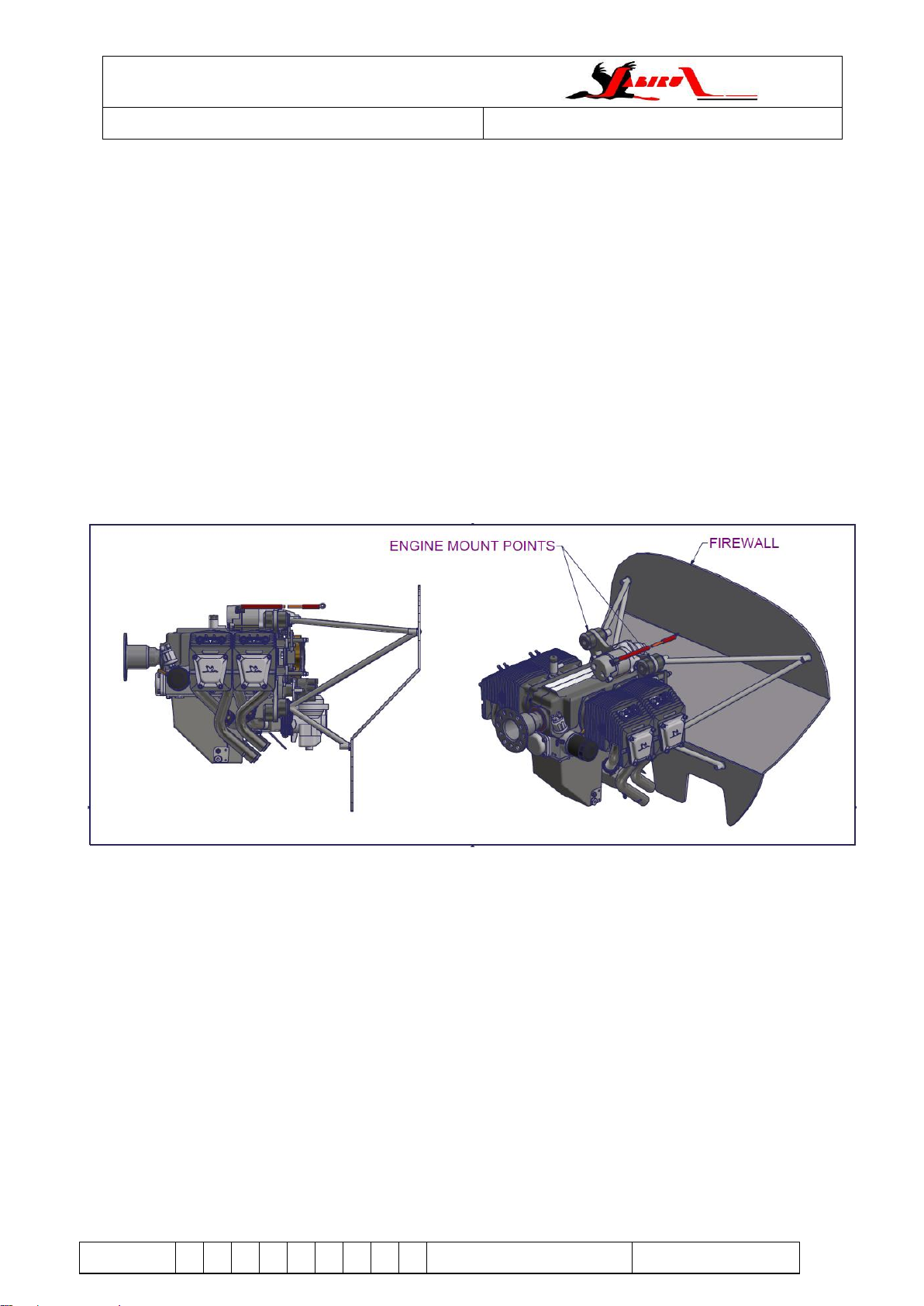
Figure 1. Engine Mount Point Locations....................................................................................................................................6
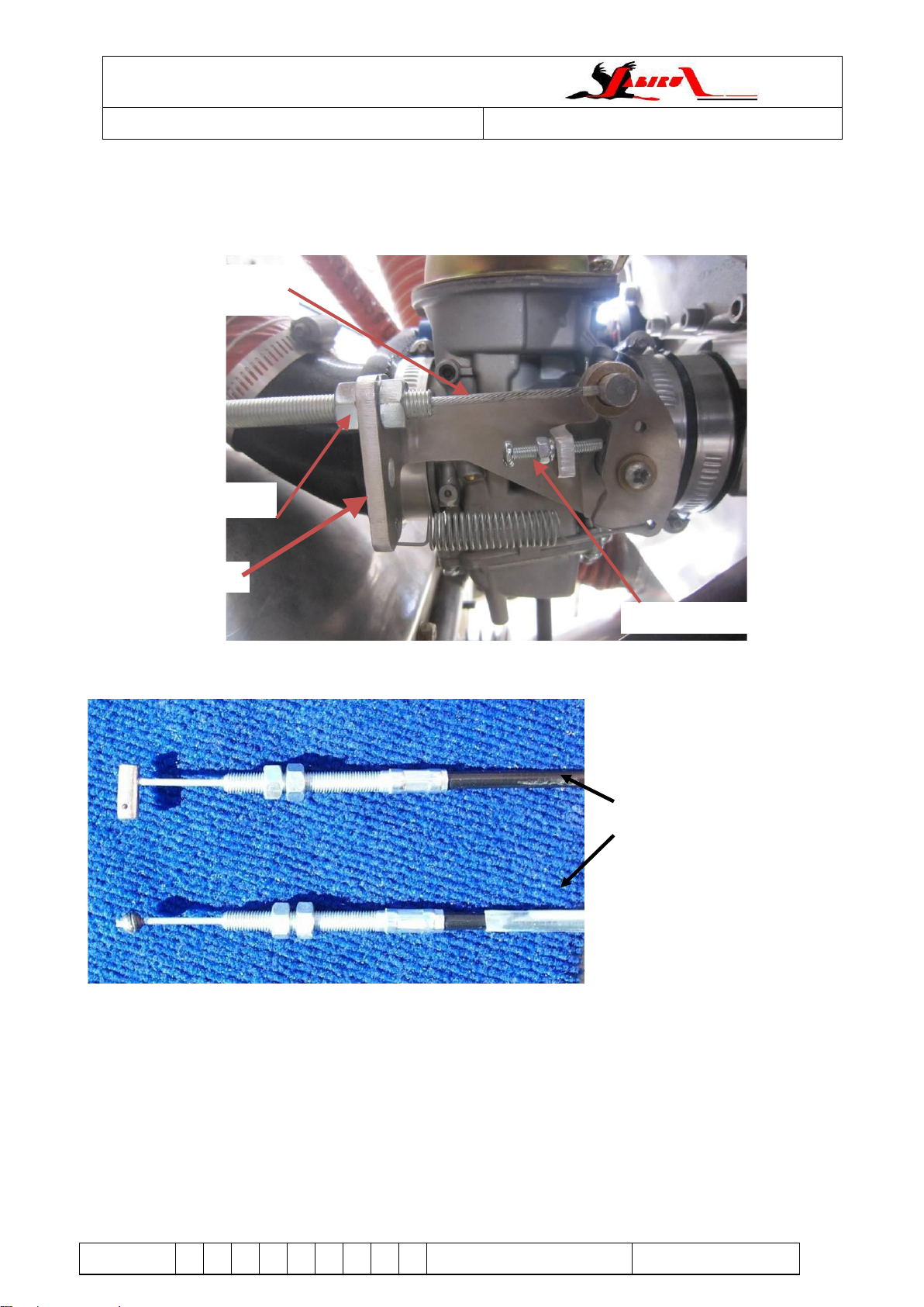
Figure 2: Throttle cable connections. ........................................................................................................................................7
Figure 3: Choke cable fitted ......................................................................................................................................................8
Figure 4: Choke cable end drawing...........................................................................................................................................8
Figure 5: Choke cable end parts in order of assembly..............................................................................................................8
Figure 6: Choke cable end assembled......................................................................................................................................9
Figure 7. Crankcase Breather Installation...............................................................................................................................10
Figure 8. Ignition and Alternator Detail....................................................................................................................................11
Figure 9. Electrics Installation to Firewall................................................................................................................................12
Figure 10. Regulator Plug Wiring Details ................................................................................................................................12
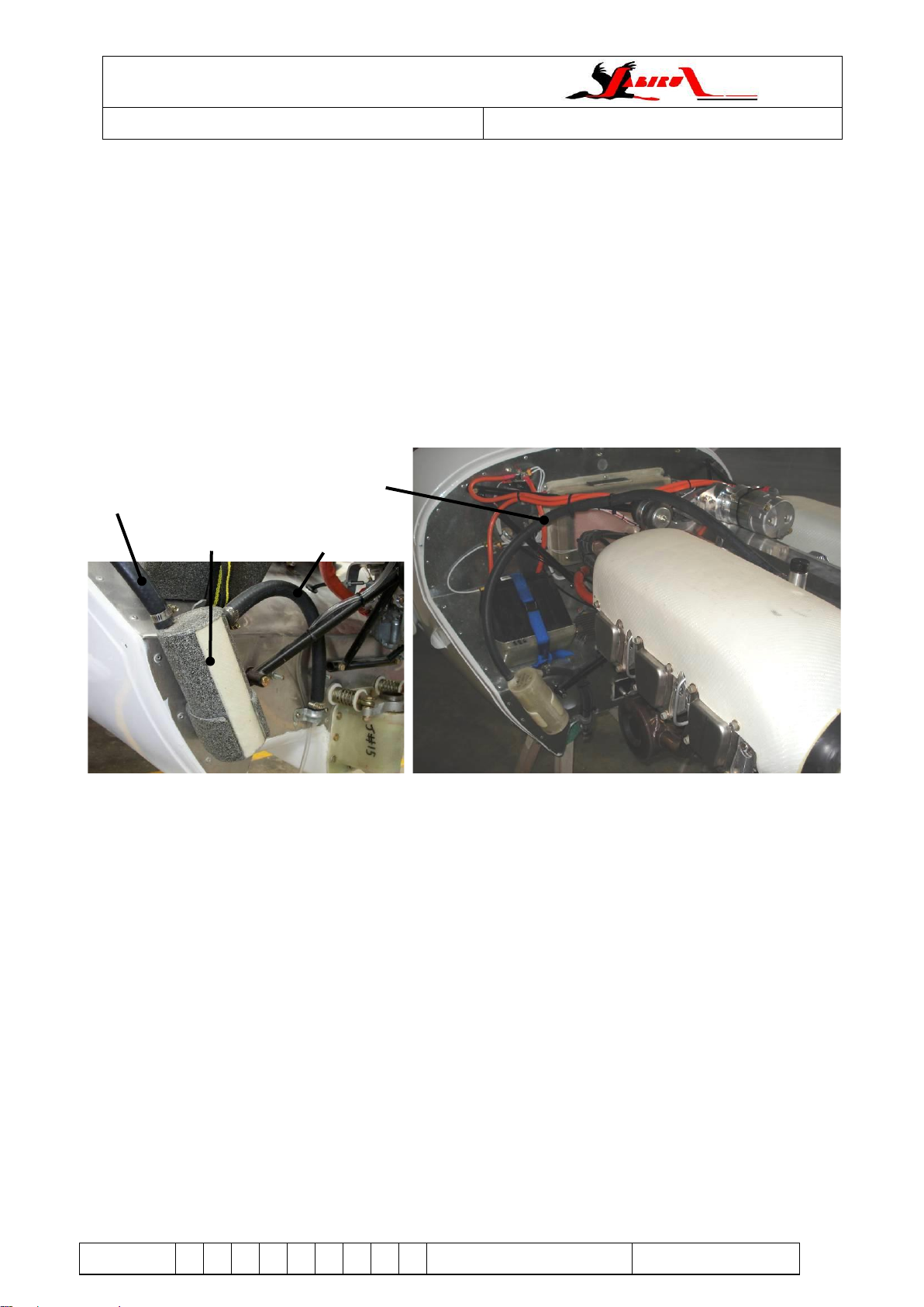
Figure 11. Ignition Coil Cooling Tube......................................................................................................................................13
Figure 12. Starter Wiring Details.............................................................................................................................................14
Figure 13: Example of engine wiring connections...................................................................................................................15
Figure 14. Tachometer Sender Installation .............................................................................................................................16
Figure 15. Inductive pickup to VDO Tachometer Connections................................................................................................17
Figure 16: Hall effect sender location on 2200 engine. ...........................................................................................................17
Figure 17: Hall effect sender mounting location on 3300 engine.............................................................................................18
Figure 18: Hall effect sender connections...............................................................................................................................18
Figure 19: Sender position......................................................................................................................................................19
Figure 20. Oil Temperature Sender.........................................................................................................................................20
Figure 21. Oil Pressure Sender...............................................................................................................................................21
Figure 22. Oil Pressure Connections ......................................................................................................................................21
Figure 23: VDO CHT sender...................................................................................................................................................22
Figure 24: CHT Sender (Thermocouple) Installation...............................................................................................................22
Figure 25: EGT sensor installation example............................................................................................................................23
Figure 26. RG400 Co-Axial Antenna Cable.............................................................................................................................24
Figure 27. Mechanical Fuel Pump...........................................................................................................................................25
Figure 28: 3300 cobra head. (other bends are available)........................................................................................................26
Figure 29: Balance tube connection on airbox........................................................................................................................26
Figure 30. Carburettor Installation...........................................................................................................................................27
Figure 31. Carburettor Intake and Balance Tube Detail..........................................................................................................27
Figure 32. Needle Jet (Jabiru Needle) ....................................................................................................................................28
Figure 33. Air Intake Connections...........................................................................................................................................30
Figure 34. Air Filter Box Plumbing –Incorrect.........................................................................................................................31
Figure 35. Air Filter Box Plumbing –Correct...........................................................................................................................31
Figure 36. Typical “Cobra Head” Installation on a Jabiru Aircraft ............................................................................................31
Figure 37. Ram Air Bleed........................................................................................................................................................32
Figure 38. Engine Accessory Pack Contents..........................................................................................................................36
Figure 39 Upper and Lower Engine Mount Detail ...................................................................................................................36
Figure 40. Engine Mount Detail...............................................................................................................................................37
Figure 41. Fuel Connections General .....................................................................................................................................38
Figure 42. SCAT Hose Detail..................................................................................................................................................38
Figure 43. Cowl Airflow (Best Viewed in Colour).....................................................................................................................41
Figure 44. Cowl Airflow (Black and White Version).................................................................................................................41
Figure 45. Flow Visualisation ..................................................................................................................................................42
Figure 46 - Position ram-air duct on engine ............................................................................................................................43
Figure 47 - Mark, Drill and sand holes and reliefs...................................................................................................................44
Figure 48 - Fitting stainless steel tags.....................................................................................................................................44
Figure 49 - Front tag installation..............................................................................................................................................45
Figure 50: Ignition coil cooling tubes.......................................................................................................................................45
Figure 51. Air Dam Installation...............................................................................................................................................46
Figure 52 - Attach insertion rubber strip..................................................................................................................................47
Figure 53. Oil Cooler Duct Design...........................................................................................................................................48
Figure 54. Oil Cooler Installation.............................................................................................................................................48
Figure 55: Lip to aid cooling as installed on a Jabiru...............................................................................................................49
Figure 56. Effect of Angle of Attack on Cowl Outlets...............................................................................................................49
Figure 57. Cowl Outlet Geometry............................................................................................................................................50
Figure 58. Outlet Restriction Caused By Flange On Lower FirewallCooling System Testing and Evaluation.........................50
Figure 59: Cooling pressure measurement.............................................................................................................................51
Figure 60: Ram Air duct pressure tapping...............................................................................................................................52
Figure 61. Augmentor Exhaust System...................................................................................................................................53

Jabiru Aircraft Pty Ltd
Installation Manual
Gen 4 2200 and 3300 engines
ISSUE
1
Dated : Aug 2021
Page: 4 of 55
1.2 List of Effective Pages
•This manual is revised as a complete document. All pages must display the same revision number. See the
table below for the revision history
Table 1 - Manual revision history
Issue
List of Changes
Issued By
Date
1
Initial Issue
DM
10/8/21

Jabiru Aircraft Pty Ltd
Installation Manual
Gen 4 2200 and 3300 engines
ISSUE
1
Dated : Aug 2021
Page: 5 of 55
1 Engine Information
All specification data relevant to the Gen 4 2200 and 3300 engine is found in the following manuals:
•JEM0005: Maintenance Manual –contains the following
oGeneral Specifications
oFuel and Oil specifications
oDetailed list of all operating limitations (temperatures, pressures, RPM etc)
oGeneral dimensions
oMaintenance procedures
•JEM0004: Engine Overhaul –contains the following.
oFastener torque settings
oBuild tolerances and clearances
oEngine disassembly
oEngine assembly
oBuild logs
•JEM0007: Production and Parts Book –contains the following
oIllustrated parts lists
oProduction assembly procedures
oRun in guidelines.
These manuals can be found at https://jabiru.net.au/service/manuals/

Jabiru Aircraft Pty Ltd
Installation Manual
Gen 4 2200 and 3300 engines
ISSUE
1
Dated : Aug 2021
Page: 6 of 55
Engine Mount
The design of the engine mount must balance many requirements:
•The mount must be strong enough to carry the loads applied by the weight and power of the engine.
•The mount must be stiff enough that the engine does not sag or move too much when power is applied.
•The mount must position the engine at the correct height and angle so that the engine’s thrust line suits the
aircraft. In most installations, Jabiru Engines need to have their thrust axis offset to the right (tractor
installations) by between 1° and 3° (depending on the model)
•The mount must position the engine at the right place. The weight of the engine is a very significant part of
the overall aircraft weight, and the position must be accounted to place the centre of gravity of the aircraft
(CG) in the correct location.
•The mount must be designed to allow enough room for the air intake to the Carburettor as well as
accessories like vacuum pumps. Access for maintenance must also be considered.
•All Jabiru aircraft models have specially designed engine mounts available. Firewall forward kits have also
been developed for a number of other light sport aircraft. Contact Jabiru aircraft or an authorised dealer for
more information
•The engine has four engine mounting points located at the rear of the engine. JEM0005 provided detailed
diagrams and dimensions for these mounting points). An optional bed mount may be fitted, which adds 2
additional mount points at the front of the engine.
Figure 1. Engine Mount Point Locations
•Each engine mounting point is rubber mounted to dampen the engine vibrations. The correct installation of
these rubbers is shown later in Figure 39.
•If required, corrections of the engine angle or propeller position can be made by fitting spacers under the
rubber cushions. The maximum spacer thickness on any one mount is 3mm.

Jabiru Aircraft Pty Ltd
Installation Manual
Gen 4 2200 and 3300 engines
ISSUE
1
Dated : Aug 2021
Page: 7 of 55
2 Controls
This section comprises of the mechanical controls and electrical switches.
2.1 Throttle and Choke
•The throttle cable attaches to the cable mount arm fitted to the carburettor.
Figure 2: Throttle cable connections.
•Note: Since a pressure compensating carburettor is used there is no mixture control.
•The idle stop for the throttle can be adjusted using the adjuster screws and nuts shown in Figure 2. A 7mm
spanner and a phillips screwdriver is required.
•The cable should be adjusted so that just before the throttle hits the full throttle stop, the carburettor throttle
lever hits the stop.
•The cables used must have an adequate radius wherever they turn a corner. Bending the cables too
sharply will increase the cable friction, making it difficult to use the control accurately. This is a particular
problem for the throttle cable as it will make setting the idle accurately, very difficult.
•The Idle Stop Screw (shown in Figure 2) must be adjusted as a part of the engine installation process to
correctly set idle RPM.
Throttle Cable connected
to throttle arm
Cable mount bracket
Cable adjustment.
Idle stop screw
Kit Throttle Cable
Throttle lever end
Carburettor end

Jabiru Aircraft Pty Ltd
Installation Manual
Gen 4 2200 and 3300 engines
ISSUE
1
Dated : Aug 2021
Page: 8 of 55
Figure 3: Choke cable fitted
•Choke cable doesn’t have any adjustment.
•Install choke cable and trim to length before fitting end ferrule to choke cable.
Figure 4: Choke cable end drawing
Figure 5: Choke cable end parts in order of assembly.
Choke Cable connected
to carburettor arm
These parts are supplied
in the carburettor.

Jabiru Aircraft Pty Ltd
Installation Manual
Gen 4 2200 and 3300 engines
ISSUE
1
Dated : Aug 2021
Page: 9 of 55
Figure 6: Choke cable end assembled.
2.2 Ignition and Starter Systems
•The only electrical controls for the Jabiru Engine are the ignition switching and the start button or starter
key.
•The ignition switches earth the corresponding corresponding coil to ground, to turn the coil off.
•The starter button provides 12V to the starter solenoid, when pressed, for engine starting.
•Section 4 gives details of the electrical systems for the engine.

Jabiru Aircraft Pty Ltd
Installation Manual
Gen 4 2200 and 3300 engines
ISSUE
1
Dated : Aug 2021
Page: 10 of 55
3 Engine Crankcase Breather, Catch Bottle and Dipstick
•The Jabiru 2200 and 3300 Gen4 engines have a crankcase breather connection built into the dipstick
housing. This is to be connected as shown in Figure 7 below.
•The catch bottle is designed to catch most oil vapour from the crankcase breather air. It must be monitored
in service and periodically emptied of waste oil.
•Figure 57 shows more clearly the outlet from the catch bottle –the catch bottle outlet is secured in the cowl
outlet. The position of this outlet and the catch bottle itself must be assessed and oriented so that the
crankcase of the engine is exposed to pressure close to ambient. If the breather is open to a high or low
pressure (partial vacuum) area the pressure inside the crankcases will also change, with unpredictable
effects on engine oil consumption, and oil flow within the engine. This is because several areas of the
engine are lubricated via low pressure or spray oil feeds, and drained by gravity –pressure differences
cause airflow changes, and modified airflow can significantly affect the oil feeds in these areas.
•When installed in a tail-dragger aircraft, re-calibration of the dipstick will be required by the owner so that it
can be read accurately with the aircraft sitting on its wheels.
Figure 7. Crankcase Breather Installation
Catch bottle
attached to firewall
Hose from engine
Hose to outlet
Hose from engine
to catch bottle

Jabiru Aircraft Pty Ltd
Installation Manual
Gen 4 2200 and 3300 engines
ISSUE
1
Dated : Aug 2021
Page: 11 of 55
4 Electrical Equipment
4.1 Alternator
•The alternator fitted to the Jabiru 2200 engine is a single phase, permanently excited with a regulator.
•The rotor is mounted on the flywheel and the stator is mounted on the alternator mount plate at the back of
the engine. The alternator mount plate is also the mount for the ignition coils and the vacuum pump.
•Note: The electrical system is Negative Earth
Specifications
Power (Max): 200W Continuous (approx. 18 Amps)
Figure 8. Ignition and Alternator Detail
4.2 Regulator
•The regulator has been selected to match the voltage and current of the integral alternator. Only Jabiru
supplied regulators should be used. (The regulator charge voltage is 14.5 volts + 0.1 volt.).
•Recommended wiring of regulator is positive and negative of the regulator directly to the battery. A 30A fuse
or circuit breaker may be used between the regulator and battery
•The voltage sense wire should be connected directly to the battery via a separate wire. Other connections
aren’t used.
Alternator rotor –
mounted on flywheel
Alternator stator –
mounted on alternator
mount plate fixed to rear
of engine.
Ignition coil (1 of 2)
Wire to ignition switch
Ignition magnets –
mounted on flywheel

Jabiru Aircraft Pty Ltd
Installation Manual
Gen 4 2200 and 3300 engines
ISSUE
1
Dated : Aug 2021
Page: 12 of 55
Figure 9. Electrics Installation to Firewall
Figure 10. Regulator Plug Wiring Details
4.3 Ignition
•The ignition unit has dual breakerless transistorised ignition with the magnets mounted on the flywheel and
the coils mounted on the alternator mount plate. Figure 8 shows the coils of a Jabiru 6-cylinder engine. For
the 2200 engine the system is the same, however the position of the coils and the magnets on the flywheel
are slightly different.
•The current from the coils flows to the distributor from where it is distributed to the spark plugs.
Starter Solenoid
Regulator (Grey, finned block)
Regulator Plug
Power / Earth cables to starter motor
Firewall
Voltage sense wire
To battery +

Jabiru Aircraft Pty Ltd
Installation Manual
Gen 4 2200 and 3300 engines
ISSUE
1
Dated : Aug 2021
Page: 13 of 55
•The ignition is turned OFF by grounding the coils via the ignition switches. This is the reverse of most
electrical systems: when the ignition switch is in the open (not connected) position the coil is LIVE and will
fire. Wiring details are shown in Figure 13
•The ignition is timed to 25° BTDC. Ignition timing is fixed –it is set by the position of the flywheel magnets
relative to the crankshaft.
•The temperature limit for the ignition coils is approximately 70°C. This should be checked by the installer. It
is recommended that pipes of 12mm dia be fitted to the top rear of each air duct directing air onto the coils
for cooling purposes.
•Coil gaps are set at 0.25mm to 0.30mm (0.010” to 0.012”).
•When installing new ignition coils the output leads go in the direction of prop rotation. RHS coil output lead
is up LHS coil output lead goes down –See Figure 8.
Figure 11. Ignition Coil Cooling Tube
4.4 Starter Motor
•The starter is mounted on the top of the engine and drives the ring gear on the flywheel.
•The motor is activated by engaging the starter button (the master switch has to be ON) which trips the
solenoid, hence current flows from the battery to the motor.
•The cable from Battery to starter should be minimum 16mm2copper.
•Wiring details are shown in Figure 13.
4.5 Starter Solenoid
•The starter Solenoid is mounted on the firewall as shown in Figure 9.
•The Solenoid body forms a part of the electrical circuit and MUST be earthed to function correctly.
Ram air cooling duct
Coil cooling tube
Ignition coil

Jabiru Aircraft Pty Ltd
Installation Manual
Gen 4 2200 and 3300 engines
ISSUE
1
Dated : Aug 2021
Page: 14 of 55
Figure 12. Starter Wiring Details
4.6 Battery
•The battery should be of a light weight, 12V, 20 Ah type able to accept a charging voltage up to 14 V (+
0.8V) and a 30 AMP Input.
•For optimum starting the battery used must have a high Cranking Amp Capacity (also known as Pulse Amp
Capacity). The standard battery used by Jabiru Aircraft has a Pulse Amp rating of 625 Amps. Batteries
with higher Pulse Amp ratings may be used and will improve engine starting in colder climates.
•Only use lead acid batteries as this is what the alternator regulator is designed to use. Do not use other
battery chemistries (e.g. Lithium). Possible consequences include a battery fire.
4.7 Wiring Practices
•Using aircraft grade wiring is strongly recommended. Compared to other grades of wire aircraft grade can
carry higher currents for the same physical size and weight. The insulation used on aircraft grade wire is
also frame resistant and is designed for better resistance to damage caused by chaffing or rubbing.
•Care should be taken to identify each wire via labels or similar. This makes troubleshooting electrical issues
much easier.
•Wherever possible wires should be identified as carrying “Power” or “Earth”. This can be done by using
different colour connectors or applying rings of coloured heat-shrink during assembly. Again, this step
simplifies troubleshooting or later modification.
•Wires should be laid out in bundles and supported along their length to prevent failures due to fatigue.

Jabiru Aircraft Pty Ltd
Installation Manual
Gen 4 2200 and 3300 engines
ISSUE
1
Dated : Aug 2021
Page: 15 of 55
Figure 13: Example of engine wiring connections.

Jabiru Aircraft Pty Ltd
Installation Manual
Gen 4 2200 and 3300 engines
ISSUE
1
Dated : Aug 2021
Page: 16 of 55
4.8 Instrumentation
4.8.1 RPM
•The engine can be fitted with the inductive pickup shown in Figure 13. Some Gen 4 engines may not be
fitted with the mount for this pickup instead the hall effect sender can be fitted instead.
•Electronic engine monitors can use the pulses from the alternator to measure engine RPM.
Inductive pickup use.
•The inductive pickup works with the VDO tachometer as stocked by Jabiru.. Detailed instructions on its
installation are supplied by the instrument manufacturer.
•The tachometer picks up on 2 metal tabs attached to the inside of the flywheel.
•The Pickup used is a Magnetic Induction sender type. It is a passive device requiring no external power.
•They Pickup outputs a voltage in response to variations in their self-induced magnetic field caused by
proximity to moving ferrous metal parts (such as the tags fitted to the rear of the flywheel).
•The Tachometer sender must be adjusted to have approximately a 0.4mm gap between the tip of the
sender and the tag. Note that due to normal bearing clearances the crankshaft moves slightly when the
engine is running, so if this gap is set too small the sender will hit the tag. The sender is fragile and most
times damage like this means that the sender must be replaced. If the gap is different for each of the two
tags then one tag can be carefully bent to be the same as the other.
•Ensure the gauge is reading correctly. While large errors will be obvious, smaller errors are harder to pick
and it is recommended to check the gauge reading with another instrument (such as a hand-held optical
prop-tach).
Figure 14. Tachometer Sender Installation
Inductive Tachometer
Sender

Jabiru Aircraft Pty Ltd
Installation Manual
Gen 4 2200 and 3300 engines
ISSUE
1
Dated : Aug 2021
Page: 17 of 55
Figure 15. Inductive pickup to VDO Tachometer Connections
Hall Effect Sender Installation
•The inductive pickup works with the VDO tachometer as stocked by Jabiru and also with some electronic
engine monitors.
•The Sender senses the magnetic fields of the ignition magnets as they pass.
•Mounts to the unused coil mount location on a Gen 4 engine.
•The output signal from the sender is a 0 –12V square wave with a rising edge each time the magnet
passes.
•This sender requires 12V power.
•Set tachometer or EMS to 2 pulses for 2200 and 3 pulses for 3300.
•Check the tacho reading at cruise rpm. On a VDO tachometer the pulses can be adjusted by increments of
0.01 to correct any error.
Figure 16: Hall effect sender location on 2200 engine.
8 7 6 5
4 3 2 1
Connect to Earth Bus
Connect to positive, such as
the Instrument Wiring Bus
Connect to Black wire of
tachometer pick-up
Connect to Red Wire of
tachometer pick-up

Jabiru Aircraft Pty Ltd
Installation Manual
Gen 4 2200 and 3300 engines
ISSUE
1
Dated : Aug 2021
Page: 18 of 55
Figure 17: Hall effect sender mounting location on 3300 engine.
Figure 18: Hall effect sender connections.
Connect to Blue Wire of hall
effect sender to terminal 8
8 7 6 5
4 3 2 1
Connect both Red wire of hall
effect sender and a +12V
source, such as instrument
bus, to terminal 4
Connect both Black wire of hall
effect sender and aircraft earth
to terminal 3.

Jabiru Aircraft Pty Ltd
Installation Manual
Gen 4 2200 and 3300 engines
ISSUE
1
Dated : Aug 2021
Page: 19 of 55
Figure 19: Sender position.
Alternator pulses
•Many Electronic Engine monitoring systems (EMS) can read the pulses from the ac voltage generated by
the alternator to measure engine rpm.
•Read EMS instructions carefully as some require resistors or fuses in this sense wire to protect the
instrument.
4.8.2 Oil Temperature Sender
•The Oil Temperature Gauge uses an electric probe mounted in the base of the sump. Jabiru supplied oil
temperature senders are recommended which will work with the Jabiru supplied analogue oil temperature
gauges and many EMS systems. Jabiru also supply Dynon oil pressure senders for Dynon EMS.
•The temperature sender is a brass fitting installed in the engine sump beside the drain plug.
•This temperature sender is an NTC thermistor.
•The oil temperature relies on a good earth connection between the sensor, the engine and the airframe
earth terminal. If there is excess resistance at any of these points gauge reading errors will occur.
Set protrusion with 2 threads
showing.
Use Loctite 243 on
threads.

Jabiru Aircraft Pty Ltd
Installation Manual
Gen 4 2200 and 3300 engines
ISSUE
1
Dated : Aug 2021
Page: 20 of 55
Figure 20. Oil Temperature Sender
Oil Temperature sender with
wire connected
Engine sump drain plug
Other manuals for 2200
6
This manual suits for next models
1
Table of contents
Other Jabiru Engine manuals
Popular Engine manuals by other brands

Graco
Graco 215-255 Instructions-parts list

Siemens
Siemens SIMOTICS HV M operating instructions

Armstrong
Armstrong 4280 Series Service work instructions

Briggs & Stratton
Briggs & Stratton 10A900 Series Illustrated parts list

GRITAL
GRITAL GR300 installation manual

Siemens
Siemens SIMOTICS S-1FG1 operating instructions