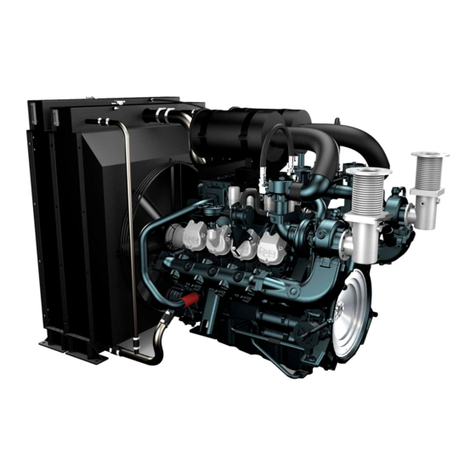
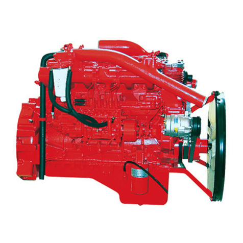
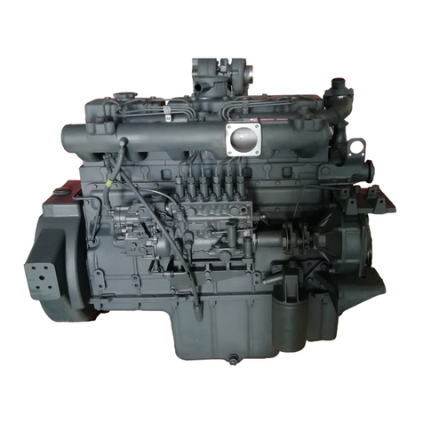
Doosan PU158TI Manual

Operation &
Maintenance Manual
GENERATOR DIESEL ENGINE
P158LE / -1 / - 2 / -S / -III
P180LE / -1 / -S / -II
P222LE / -1 / -S / -II
POWER UNIT DIESEL ENGINE
PU158TI
PU180TI
PU222TI
65.99897-8076C

FOREWORD
This manual is designed to serve as an instruction for Diesel generator engine and Power Unit engine of
DOOSAN series (P158LE /P180LE /P222LE, PU158TI/ PU180TI/ PU222TI).
The engines are 4 strokes, 2 valves per cylinder, V-type, and direct injection mode and thus, are also satisfying
with various features required as generator and power unit engine such as quiet operation, economical fuel
consumption, durability in high speed operation and so forth.
We are very confident that these engine series are quite superior to any high speed engines in economy and
efficiency. However, high performance and long life cycle will be accomplished when a proper handling and
administration of periodic inspections and maintenance should be observed. Readers are desired to know for
your reference that those kinds of maintenance matters are explained here in detail by means of figures and
diagrams.
In this manual, the following symbols are used to indicate the type of service operations to be performed.
Removal Adjustment
Installation Cleaning
Disassembly Pay close attention-Important
Reassembly Tighten to specified torque
Align the marks Use special tools of manufacturer's
Directional Indication Lubricate with oil
Inspection Lubricate with grease
Measurement
If you have any question or recommendation in connection with this manual, please do not hesitate to contact
our head office, dealers or authorized service shops near by your location for any services.
For the last, the contents of this instruction manual may be changed without prior notice for some quality
improvement. Thank you.
Doosan Infracore Co., Ltd.
Jan. 2008

CONTENTS
1. Safety Regulations & Engine Specifications
1.1. Safety regulations ............................................................................................................................... 1
1.2. Engine Specification ........................................................................................................................... 5
1.3. Engine Assembly .............................................................................................................................. 11
2. Technical Information
2.1. Engine Model and Serial Number ..................................................................................................... 19
2.2. Engines Characteristic ...................................................................................................................... 20
2.3. Troubleshooting ................................................................................................................................ 41
2.4. Operation tip ..................................................................................................................................... 51
3. Disassembly and Reassembly of Major Components
3.1. Engine Disassembly ......................................................................................................................... 52
3.2. Inspection ......................................................................................................................................... 62
3.3. Engine Reassembly .......................................................................................................................... 81
3.4. Breaking-In ....................................................................................................................................... 98
4. Commissioning and Operation
4.1. Preparations ..................................................................................................................................... 99
4.2. Starting ............................................................................................................................................. 99
4.3. Running in ...................................................................................................................................... 100
4.4. During operation ............................................................................................................................. 100
4.5. Shutting down ................................................................................................................................. 100
4.6. Maintenance and Care ................................................................................................................... 101
5. Maintenance of Major Components
5.1. Fuel Injection System ..................................................................................................................... 105
5.2. Cooling System .............................................................................................................................. 126
5.3. Lubricating System ......................................................................................................................... 129
5.4. Turbo Charger ................................................................................................................................ 131
5.5. Installation ...................................................................................................................................... 140
5.6. Air Cleaner ...................................................................................................................................... 143
5.7. Tightening Cylinder Head Bolts ...................................................................................................... 145
5.8. V-belts ............................................................................................................................................ 146
6. Special Tool List
................................................................................................................................. 149
z
Appendix
z
Parts & After Service Center
z
Worldwide Network

Safety Regulations & Engine Specifications
- 1 -
1. Safety Regulations & Engine Specifications
1.1. Safety Regulations
1.1.1. General notes
Handling diesel engines and the necessary resources is no problem when the personnel commissioned
with operation and maintenance are trained accordingly and use their common sense.
This summary is a compilation of the most important regulations, These are broken down into main
sections which contain the information necessary for preventing injury to persons, damage to property
and pollution. In addition to these regulations those dictated by the type of engine and its site are to be
observed also.
IMPORTANT :
If despite all precautions, an accident occurs, in particular through contact with
caustic acids, fuel penetrating the skin, scalding from oil, antifreeze being splashed
in the eyes etc, consult a doctor immediately.
1.1.2. Regulations designed to prevent accidents
1) During commissioning, starting and operation
z
Before putting the engine into operation for the first time, read the operating instructions carefully
and familiarize yourself with the “critical” points, If you are unsure, ask your DHI representative.
z
For reasons of safety we recommend you attach a notice to the door of the engine room
prohibiting the access of unauthorized persons and that you draw the attention of the operating
personal to the fact that they are responsible for the safety of persons who enter the engine room.
z
The engine must be started and operated only by authorized personnel. Ensure that the engine
cannot be started by unauthorized persons.
z
When the engine is running, do not get too close to the rotating parts. Wear close-fitting clothing.
z
Do not touch the engine with bare hands when it is warm from operation risk of bums.
z
Exhaust gases are toxic. Comply with the instructions for the installation of DHI Diesel engines
which are to be operated in enclosed spaces. Ensure that there is adequate ventilation and air
extraction.
z
Keep vicinity of engine, ladders and stairways free of oil and grease. Accidents caused by slipping
can have serious consequences.

Safety Regulations & Engine Specifications
- 2 -
2) During maintenance and care
z
Always carry out maintenance work when the engine is switched off. If the engine has to be
maintained while it Is running, e.g. changing the elements of change-over filters, remember that
there is a risk of scalding. Do not get too close to rotating parts.
z
Change the oil when the engine is warm from operation.
CAUTION :
There is a rise of burns and scalding. Do not touch oil drain plug or oil filters with
bare hands.
z
Take into account the amount of oil in the sump. Use a vessel of sufficient size to ensure that the
oil will not overflow.
z
Open the coolant circuit only when the engine has cooled down. If opening while the engine is still
warm is unavoidable, comply with the instructions in the chapter “Maintenance and Care”.
z
Neither tighten up nor open pipes and hoses (lube oil circuit, coolant circuit and any additional
hydraulic oil circuit) during the operation. The fluids which flow out can cause injury.
z
Fuel is inflammable. Do not smoke or use naked lights in its vicinity. The tank must be filled only
when the engine is switched off.
z
When using compressed air, e.g. for cleaning the radiator, wear goggles.
z
Keep service products (anti-freeze) only in containers which can not be confused with drinks
containers.
z
Comply with the manufacturer’s instructions when handling batteries.
CAUTION :
Accumulator acid is toxic and caustic. Battery gases are explosive.
3) When carrying out checking, setting and repair work
z
Checking, setting and repair work must be carried out by authorized personnel only.
z
Use only tools which are in satisfactory condition. Worn open-end wrench slip. which could lead to
Injury.
z
When the engine is hanging on a crane, no-one must be allowed to stand or pass under it. Keep
lifting gear in good condition.
z
When working on parts which contain asbestos, comply with the notes at the end of this chapter.
z
When checking injectors do not put your hands under the jet of fuel. Do not inhale atomized fuel.
z
When working on the electrical system disconnect the battery earth cable first. Connect it up
again last in prevent short circuits.

Safety Regulations & Engine Specifications
- 3 -
1.1.3. Regulations designed to prevent damage to engine and premature wear
1) Never demand more of the engine than it was designed to yield for its intended purpose.
z
Detailed information on this can be found in the sales literature. The injection pump must not be
adjusted without prior written permission of DHI.
2) If faults occur, find the cause immediately and have it eliminated in order to prevent more serious of
damage.
3) Use only genuine DHI spare parts. DHI will accept no responsibility for damage resulting from the
installation of other parts which are supposedly “just as good”.
4) In addition to the above, note the following points.
z
Never let the engine run when dry, i.e. without lube oil or coolant.
z
Use only DHI-approved service products (engine oil , anti-freeze and anticorrosion agent).
z
Pay attention to cleanliness. The Diesel fuel must be free of water. See “Maintenance and care”.
z
Have the engine maintained at the specified intervals.
z
Do not switch off the engine immediately when it is warm, but let it run without load for about 5
minutes so that temperature equalization can take place.
z
Never put cold coolant into an overheated engine. See “Maintenance and care”.
z
Do not add so much engine oil that the oil level rises above the max. marking on the dipstick. Do
not exceed the maximum permissible tilt of the engine. Serious damage to the engine may result
if these instructions are not adhered to.
z
Always ensure that the testing and monitoring equipment (for battery charge, oil pressure, coolant
temperature) function satisfactorily.
z
Comply with instructions for operation of the alternator. See “Commissioning and operation”.
z
Do not let the raw water pump run dry, If there is a risk of frost, drain the pump when the engine is
switched off.
1.1.4. Regulations designed to prevent pollution
1) Engine oil, filter elements, fuel filters
z
Take old oil only to an oil collection point.
z
Take strict precautions to ensure that oil does not get into the drains or into the ground. The
drinking water supply could be contaminated.
z
Filter elements are classed as dangerous waste and must be treated as such.
2) Coolant
z
Treat undiluted anti-corrosion agent and / or antifreeze as dangerous waste.
z
When disposing of spent coolant comply with the regulations of the relevant local authorities.
1.1.5. Notes on safety in handling used engine oil
Prolonged or repeated contact between the skin and any kind of engine oil decreases the skin.
Drying, irritation or inflammation of the skin may therefore occur. Used engine oil also contains
dangerous substances which have caused skin cancer in animal experiments. If the basic rules of
hygiene and health and safety at work are observed, health risks are not to the expected as a result of
handling used engine oil.

Safety Regulations & Engine Specifications
- 4 -
Health precautions :
z
Avoid prolonged or repeated skin contact with used engine oil.
z
Protect your skin by means of suitable agents (creams etc.) or wear protective gloves.
z
Clean skin which has been in contact with engine oil.
-
Wash thoroughly with soap and water, A nailbrush is an effective aid.
-
Certain products make it easier to clean your hands.
-
Do not use petrol, Diesel fuel, gas oil, thinners or solvents as washing agents.
z
After washing apply a fatty skin cream to the skin.
z
Change oil-soaked clothing and shoes.
z
Do not put oily rags into your pockets.
Ensure that used engine oil is disposed of properly.
- Engine oil can endanger the water supply -
For this reason do not let engine oil get into the ground, waterways, the drains or the sewers.
Violations are punishable.
Collect and dispose of used engine oil carefully. For information on collection points please contact the
seller, the supplier or the local authorities.
1.1.6. General repair instructions
1. Before performing service operation, disconnect the grounding cable from the battery for reducing
the chance of cable damage and burning due to short-circuiting.
2. Use covers for preventing the components from damage or pollution.
3. Engine oil and anti-freeze solution must be handled with reasonable care as they cause paint
damage.
4. The use of proper tools and special tools where specified is important to efficient and reliable service
operation.
5. Use genuine DOOSAN parts necessarily.
6. Used cotter pins, gaskets, O-rings, oil seals, lock washer and self-lock nuts should be discarded and
new ones should be prepared for installation as normal function of the parts can not be maintained if
these parts are reused.
7. To facilitate proper and smooth reassemble operation, keep disassembled parts neatly in groups.
Keeping fixing bolts and nut separate is very important as they vary in hardness and design
depending on position of installation.
8. Clean the parts before inspection or reassembly. Also clean oil ports, etc. using compressed air to
make certain they are free from restrictions.
9. Lubricate rotating and sliding faces of parts with oil or grease before installation.
10. When necessary, use a sealer on gaskets to prevent leakage.
11. Carefully observe all specifications for bolts and nuts torques.
12. When service operation is completed, make a final check to be sure service has been done
property.

Safety Regulations & Engine Specifications
- 5 -
1.2. Engine Specification
1.2.1. Specification for generator engine
Engine Model
Items P158LE series P180LE series P222LE series
Engine type Water-cooled, 4 cycle Vee type
Turbo charged & intercooled
Combustion chamber type Direct injection type
Cylinder liner type Wet type, chromated or casting liner
Timing gear system Gear driven type
No. of piston ring Compression ring 2, oil ring 1
No. of cylinder-bore × stroke (mm) 8 – 128 × 142 10 – 128 × 142 12 – 128 × 142
Total piston displacement (cc) 14,618 18,273 21,927
Compression ratio
P158LE/-1/-2, P180LE/-1, P222LE/-1 => 15.0 : 1
P158LE-S/-III, P180LE-S/-II, P222LE-S/-II => 14.6 : 1
P222LE-II(EAYQD) => 14.0 : 1
Engine dimension
(length × width × height) (mm)
1,484
×
1,389
×
1,161.5
1,557
×
1,389
×
1,248 1,717
×
1,389
×
1,288
Engine dry weight (kg)
P158LE/-1/-2 : 950
P158LE-S/-III : 961
P180LE/-1 : 1,175
P180LE-S/-II : 1,188
P222LE/-1 : 1,575
P222LE-S/-II : 1,591
Fuel injection order
1-5-7-2-6-3-4-8
1-6-5-10-2-7-3-8-4-9
1-12-5-8-3-10-6-7-
2-11-4-9
Injection pump type Bosch in-line P type
Governor type Electrical type
Injection nozzle type Multi-hole type
Fuel injection pressure (kg/cm
2
)285
Compression pressure (kg/cm
2
) 28 (at 200 rpm)
Intake and exhaust valve clearance
(at cold) (mm) 0.3 / 0.4
Intake valve Open at 24
°
(B.T.D.C)
Close at 36
°
(A.B.D.C)
Exhaust valve Open at 63
°
(B.B.D.C)
Close at 27
°
(A.T.D.C)
Lubrication method Fully forced pressure feed type
Oil pump type Gear type
Oil filter type Full-flow, cartridge type
Lubricating oil capacity (max./min.) (lit) 21 / 17 35 / 28 40 / 33
Oil cooler type Water cooled
Water pump Centrifugal type driven by belt
Cooling Method Pressurized circulation
Cooling water capacity (engine only) (lit)
20 21 23
Thermostat type Wax pallet type (71 ~ 85
°
C)
Alternator voltage – capacity (V – A) 24 – 45
Starting Motor voltage – output (V
–
kW)
24 – 7.0
Battery capacity (V – AH) 24 – 200

Safety Regulations & Engine Specifications
- 6 -
1.2.2. Specification for power unit engine
Engine Model
Items PU158TI PU180TI PU222TI
Engine type Water-cooled, 4 cycle Vee type
Turbo charged & intercooled
Combustion chamber type Direct injection type
Cylinder liner type Wet type, chromated or casting liner
Timing gear system Gear driven type
No. of piston ring Compression ring 2, oil ring 1
No. of cylinder-bore × stroke (mm) 8 – 128 × 142 10 – 128 × 142 12 – 128 × 142
Total piston displacement (cc) 14,618 18,273 21,927
Compression ratio 15 : 1
Engine dimension
(length × width × height) (mm)
1,484
×
1,389
×
1,161.5
1,557
×
1,389
×
1,248 1,717
×
1,389
×
1,288
Engine dry weight (kg) 950 1,175 1,575
Fuel injection order 1-5-7-2-6-3-4-8
1-6-5-10-2-7-3-8-4-9
1-12-5-8-3-10-6-7-
2-11-4-9
Injection pump type Bosch in-line P type
Governor type Mechanical type
Injection nozzle type Multi-hole type
Fuel injection pressure (kg/cm
2
)285
Compression pressure (kg/cm
2
) 28 (at 200 rpm)
Intake and exhaust valve clearance
(at cold) (mm) 0.3 / 0.4
Intake valve Open at 24
°
(B.T.D.C)
Close at 36
°
(A.B.D.C)
Exhaust valve Open at 63
°
(B.B.D.C)
Close at 27
°
(A.T.D.C)
Lubrication method Pressurized circulation
Oil pump type Gear type
Oil filter type Full-flow, cartridge type
Lubricating oil capacity (max./min.) (lit) 21 / 17 35 / 28 40 / 33
Oil cooler type Water cooled
Water pump Centrifugal type driven by belt
Cooling Method Pressurized circulation
Cooling water capacity (engine only) (lit)
20 21 23
Thermostat type Wax pallet type (71 ~ 85
°
C)
Alternator voltage – capacity (V – A) 24 – 45
Starting Motor voltage – output (V
–
kW)
24 – 7.0
Battery capacity (V – AH) 24 – 200

Safety Regulations & Engine Specifications
- 7 -
1.2.3. Engine power for generator
Production tolerance : ±5%
* Note : All data are based on operation without cooling fan at ISO 3046
Engine model
Condition
HZ Timing
(BTDC) Prime Stand by
P158LE
P158LE-2
(EAZOC/QC)
50 HZ(1,500 rpm) 16 399 PS(293 kW) 437 PS(321 kW)
60 HZ(1,800 rpm) 16 470 PS(346 kW) 510 PS(375 kW)
P158LE-1
(EAZOB/QB)
50 HZ(1,500 rpm) 16 444 PS(327 kW) 492 PS(362 kW)
60 HZ(1,800 rpm) 16 498 PS(366 kW) 546 PS(402 kW)
P158LE
(EAZOA/QA)
50 HZ(1,500 rpm) 16 494 PS(363 kW) 563 PS(414 kW)
60 HZ(1,800 rpm) 16 547 PS(402 kW) 623 PS(458 kW)
P158LE-S
(EAZOG/H/QG)
50 HZ(1,500 rpm) 12 546 PS(402 kW) 600 PS(441 kW)
60 HZ(1,800 rpm) 16 600 PS(441 kW) 654 PS(481 kW)
P158LE-III
(EAZOF) 60 HZ(1,800 rpm) 16 – 690 PS(508 kW)
P180LE
P180LE-1
(EASOB/QB)
50 HZ(1,500 rpm) 16 548 PS(403 kW) 601 PS(442 kW)
60 HZ(1,800 rpm) 16 617 PS(454 kW) 677 PS(498 kW)
P180LE
(EASOA/QA)
50 HZ(1,500 rpm) 16 602 PS(443 kW) 674 PS(496 kW)
60 HZ(1,800 rpm) 16 676 PS(497 kW) 734 PS(540 kW)
P180LE
(EASOC) 60 HZ(1,800 rpm) 18 695 PS(511 kW) 764 PS(562 kW)
P180LE-S
(EASOE/F/QE)
50 HZ(1,500 rpm) 16 615 PS(452 kW) 674 PS(496 kW)
60 HZ(1,800 rpm) 16 705 PS(519 kW) 771 PS(567 kW)
P180LE-II
(EASOD) 60 HZ(1,800 rpm) 16 – 827 PS(608 kW)
P222LE
P222LE-1
(EAYOB/QB)
50 HZ(1,500 rpm) 16 696 PS(512 kW) 752 PS(553 kW)
60 HZ(1,800 rpm) 16 765 PS(563 kW) 850 PS(625 kW)
P222LE
(EAYOA/QA)
50 HZ(1,500 rpm) 16 723 PS(532 kW) 781 PS(574 kW)
60 HZ(1,800 rpm) 16 803 PS(591 kW) 883 PS(649 kW)
P222LE
(EAYOC) 60 HZ(1,800 rpm) 18 803 PS(591 kW) 898 PS(660 kW)
P222LE-S
(EAYOE/F/QE)
50 HZ(1,500 rpm) 20 750 PS(552 kW) 820 PS(603 kW)
60 HZ(1,800 rpm) 19 850 PS(625 kW) 927 PS(682 kW)
P222LE-II
(EAYOD/QD)
50 HZ(1,500 rpm) 13 – 886 PS(652 kW)
60 HZ(1,800 rpm) 19 – 1000 PS(736 kW)

Safety Regulations & Engine Specifications
- 8 -
1.2.4. Engine performance curve
1) PU158TI engine
Performance ISO 3046, DIN 6270B
Output (max.) 397 kW (540 PS) / 2,100 rpm
Torque (max) 2,117 N
⋅
m (216 kg
⋅
m) / 1,500 rpm
100
125
150
175
200
225
250
Torque (kg.m)
Engine Speed (rpm)
100
150
200
250
300
350
400
450
500
550
600
Power (PS)
EH5OM001
900 1,000 1,000 1,200 1,300 1,400 1,500 1,600 1,700 1,800 1,900 2,000 2,100 2,200

Safety Regulations & Engine Specifications
- 9 -
2) PU180TI engine
Performance ISO 3046, DIN 6270B
Output (max.) 478 kW (650 PS) / 2,100 rpm
Torque (max) 2,303 N
⋅
m (235 kg
⋅
m) / 1,500 rpm
125
150
175
200
225
250
275
Torque (kg.m)
Engine Speed (rpm)
200
250
300
350
400
450
500
550
600
650
700
Power (PS)
EH5OM002
900 1,000 1,000 1,200 1,300 1,400 1,500 1,600 1,700 1,800 1,900 2,000 2,100 2,200

Safety Regulations & Engine Specifications
- 10 -
3) PU222TI engine
Performance ISO 3046, DIN 6270B
Output (max.) 588 kW (800 PS) / 2,100 rpm
Torque (max) 3,205 N
⋅
m (327 kg
⋅
m) / 1,500 rpm
200
225
250
275
300
325
350
Torque (kg.m)
900 1,000 1,000 1,200 1,300 1,400 1,500 1,600 1,700 1,800 1,900 2,000 2,100 2,200
Engine Speed (rpm)
250
400
350
300
450
500
550
600
650
700
750
800
850
Power (PS)
EH5OM003

Safety Regulations & Engine Specifications
- 11 -
1.3. Engine Assembly
1.3.1. Engine sectional view (Longitudinal)
1. Piston 11. Vibration damper
2. Combustion camper 12. Oil spray nozzle
3. Valve 13. Oil pan
4. Tappet 14. Oil suction pipe
5. Cam shaft 15. Oil pump relief valve
6. Turbocharger 16. Flywheel housing
7. Piston pin 17. Flywheel
8. Thermostat 18. Oil seal
9. Cooling fan 19. Crank shaft
10. Crank shaft pulley
9
8
7
12 3 45 6
12 13 14 15
16
17
18
19
1110
EA6O1004

Safety Regulations & Engine Specifications
- 12 -
1.3.2. Engine sectional view (Cross)
1. Cylinder head 8. Cylinder block
2. Cylinder head cover 9. Oil filter
3. Push rod 10. Oil cooler
4. Injection pump 11. Connecting rod
5. Intake manifold 12. Exhaust manifold
6. Injection pipe 13. Cylinder liner
7. Oil filler cap 14. Starter
12
8
9
10
12
13
14
11
3456 7
EA6O1005

Safety Regulations & Engine Specifications
- 13 -
1.3.3. Engine assembly views
1) PU158TI : Power unit engine
1. Cooling fan 9. Air pipe
2. Water outlet (Turbocharger to inter cooler)
3. Air pipe 10. Idle pulley
(Intercooler to intake manifold) 11. Injection pump
4. Fuel filter 12. Fly wheel housing
5. Breather 13. Cylinder head
6. Turbo charger 14. Oil filter
7. Air pipe 15. Cylinder head cover
(
Air cleaner to turbocharger)
16. Oil filler cap
8. Mounting bracket
1
2
3
4567
8
9
10
15
14
13
12
11
16
EH5OM004

Safety Regulations & Engine Specifications
- 14 -
2) PU180TI : Power unit engine
1. Cooling fan 9. Air pipe
2. Water outlet (Turbocharger to inter cooler)
3. Air pipe 10. Starter
(Intercooler to intake manifold) 11. Idle pulley
4. Fuel filter 12. Injection pump
5. Breather 13. Fly wheel housing
6. Turbo charger 14. Cylinder head
7. Air pipe 15. Oil filter
(
Air cleaner to turbocharger)
16. Oil filler cap
8. Mounting bracket 17. Cylinder head cover
1
2
3
4
567
8
9
10
15
14
13
12
11
16
17
EH5OM005

Safety Regulations & Engine Specifications
- 15 -
3) PU222TI : Power unit engine
1. Cooling fan 9. Air pipe
2. Water outlet (Turbocharger to inter cooler)
3. Air pipe 10. Idle pulley
(Intercooler to intake manifold) 11. Injection pump
4. Fuel filter 12. Fly wheel housing
5. Breather 13. Cylinder head
6. Turbo charger 14. Oil filter
7. Air pipe 15. Oil filler cap
(
Air cleaner to turbocharger)
16. Cylinder head cover
8. Starter
1
2
3
4
5
67
8
9
10
15
14
13
12
11
16
EH5OM006

Safety Regulations & Engine Specifications
- 16 -
4) P158LE : Generator engine
1. Cooling fan 10. Oil filler cap 18. Air pipe
2. Air pipe 11. Pick up sensor (Air cleaner to turbocharger)
3. Cylinder head cover 12. Oil cooler 19. Fuel filter
4. Turbocharger 13. Alternator 20. Air pipe
5. Oil drain valve 14. Exhaust elbow (Turbocharger to inter cooler)
6. Oil pan 15. Air pipe 21. Idle pulley
7. Starter (Air cleaner to turbocharger) 22. Engine mounting bracket
8. Flywheel housing 16. Oil filter 23. Water pump
9. Exhaust manifold 17. Cooling water outlet
EA6O1001
151
14
910 18 17
23
16
22
12
11
16 13
19
16
20
22
21
234

Safety Regulations & Engine Specifications
- 17 -
5) P180LE : Generator engine
1. Cooling fan 10. Oil filler cap 18. Air pipe
2. Air pipe 11. Pick up sensor (Air cleaner to turbocharger)
3. Cylinder head cover 12. Oil cooler 19. Fuel filter
4. Turbocharger 13. Alternator 20. Air pipe
5. Oil drain valve 14. Exhaust elbow (Turbocharger to inter cooler)
6. Oil pan 15. Air pipe 21. Idle pulley
7. Starter (Air cleaner to turbocharger) 22. Engine mounting bracket
8. Flywheel housing 16. Oil filter 23. Water pump
9. Exhaust manifold 17. Cooling water outlet
123
5
910
11
12 16 13
18 17 19 20
21
22
23
16
22
67 8
415
14
16
EA6O1002
This manual suits for next models
12
Table of contents
Other Doosan Engine manuals
Popular Engine manuals by other brands

Textron
Textron MPE 850 MARINE Service manual

Oriental motor
Oriental motor BMU Series quick start guide

woodmizer
woodmizer LT28 G19 Safety, Operation, Maintenance & Parts Manual

ZIEHL-ABEGG
ZIEHL-ABEGG ZAtop SM250.80D Assembly instructions

Briggs & Stratton
Briggs & Stratton 402400 Series owner's manual

Briggs & Stratton
Briggs & Stratton 110400 Operating & maintenance instructions