Falco e-motors Hx User manual

DRAFT
1
User Manual
Page 1 of 18
Rev. 0 March 23, 2013

DRAFT
2
Welcome to the e
-
Bike
world & Thank you for believing
the
Falco e
-
motors intelligent energy management system, one of the leading e-Bike
systems in the market. Adaptable, powerful, light and regenerative it will
provide you with a Falco e-motors sensation….
Please spend your few valuable minutes to read this manual. It will guide
you through the distinctive features, functions, easy care and easy use of
your Falco e-motors kit (the future of electric bike propulsion system).
We are convinced that this product will bring you immense satisfaction
and riding pleasure for many years to come.
Sincerely,
Rakesh K Dhawan
President & CEO Falco e-Motors.
Preface
Page 2 of 18
Rev. 0 March 23, 2013

DRAFT
3
INDEX
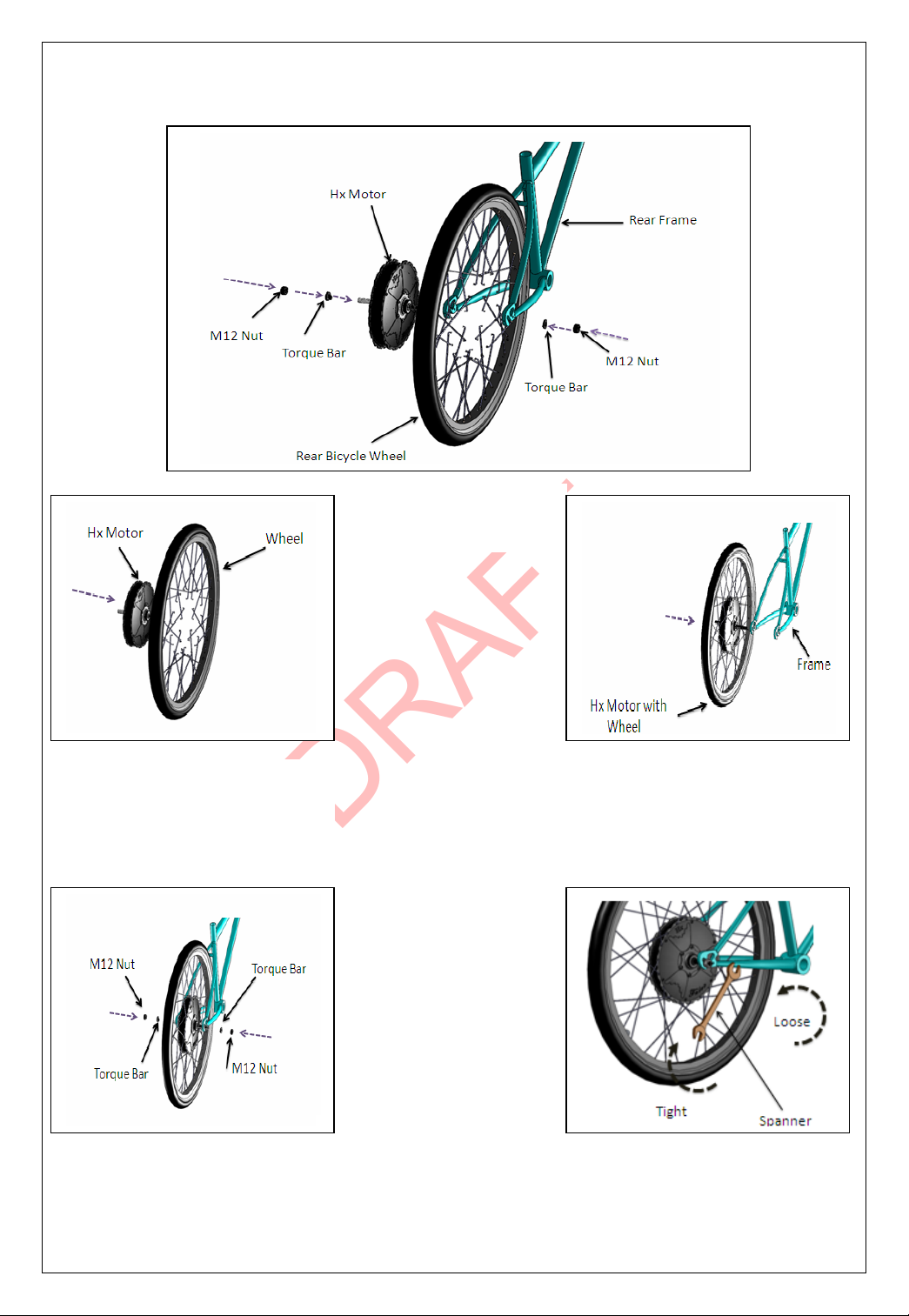
Hx Motor Installation ……………………………………………………………………… 4
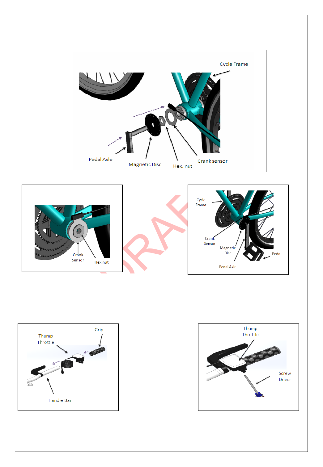
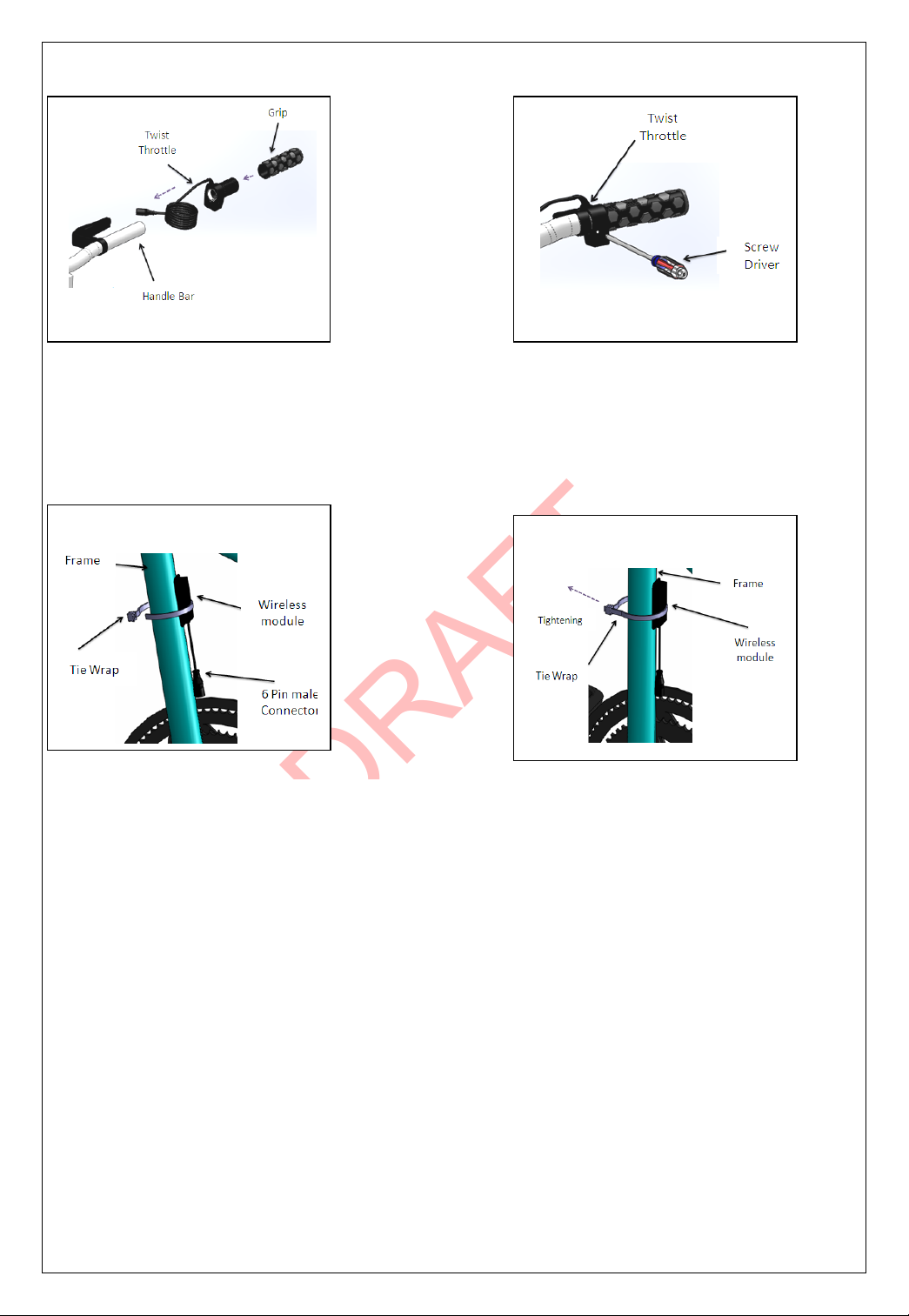
Activation sensor & Communication ……………………………………………… 5
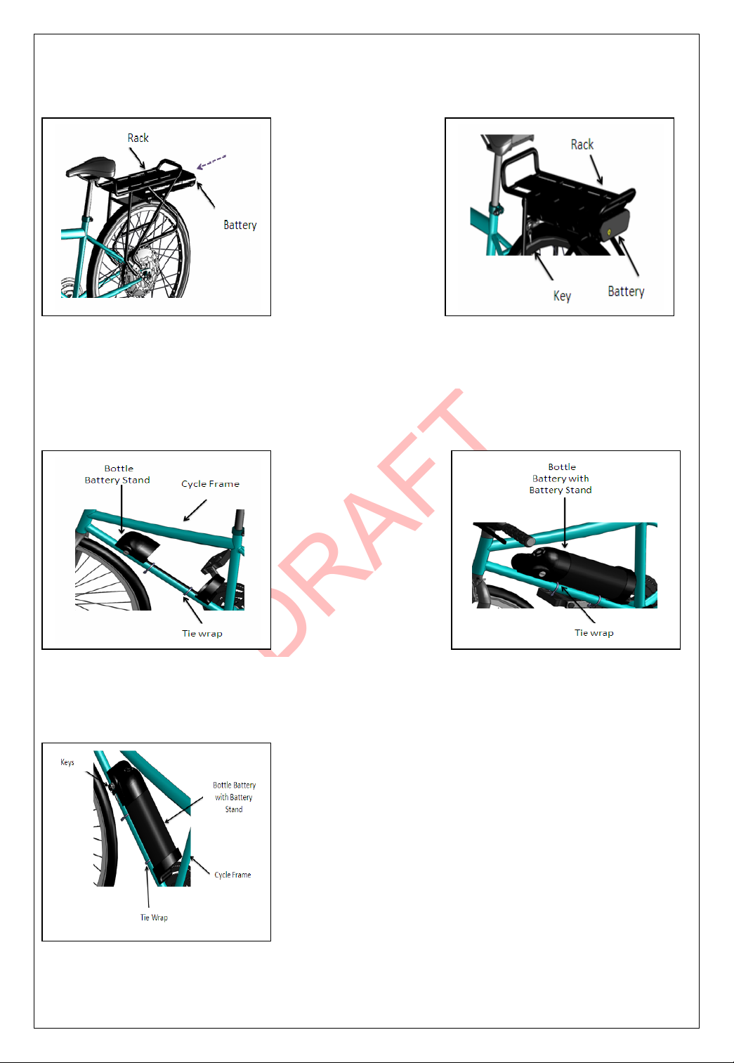
Battery Installation ………………………………………………………………………….. 7
Console Installation ………………………………………………………………………… 8
Hx Display ………………………………………………………………………………………. 9
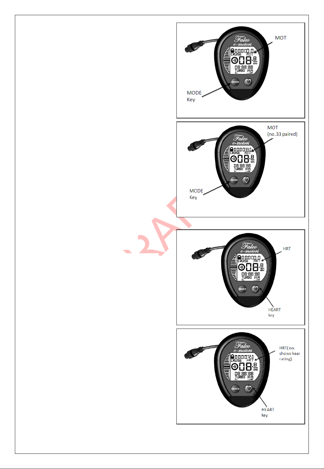
1. Motor& Heart Rate Pairing ………………………………………………………. 10
2. Mode Setting …………………………………………………………………………….. 11
3. Clock/Odometer/Wheel Setting ………………………………………………… 12
Wiring Connection …………………………………………………………………………. 14
Maintenance & Care ……………………………………………………………………….. 15
Trouble Shooting …………………………………………………………………………… 17
Contact Us ……………………………………………………………………………………… 18
Page 3 of 18
Rev. 0 March 23, 2013

DRAFT
4
1. Spoke the Hx motor with
wheel.
2. Put a wheel into frame.
3. Fit M12 & Torque Bar on
Both side frame.
4. Tighten up the nut using
suitable spanner.
Hx
Motor Installation
All Parts Label
Note : Please Avoid Over tigthening.
Page 4 of 18
Rev. 0 March 23, 2013

DRAFT
5
.
1. Place the crank sensor to the right
side of the pedal axle, tighten it with
Hex.nut.
2.Now place the Magnetic disc on
pedal Axle. close to crank sensor.
Tighten up the pedal axle & Pedal
with their respective nut.
All Parts Label
Activation Sensor
& Communication
Crank Sensor
Thump Throttle
1.
Remove Bicycle handle grip
and insert Thump throttle. 2. Tighten the thump throttle
using proper screw driver.
Note : Please Avoid Over tigthening.
Page 5 of 18
Rev. 0 March 23, 2013

DRAFT
6
Twist Throttle
1. Remove Bicycle handle grip and
insert Twist throttle. 2. Tighten the twist throttle proper
screw driver.
Wireless Module
1.Hold the wireless module along bicycle
frame & wrap with help of tie wrap.
2
.
tighten the tie wrap.
Note : Please Avoid Over tigthening.
Page 6 of 18
Rev. 0 March 23, 2013

DRAFT
7
1.Insert battery into rear rack casing.
2 .Lock the battery with help of
keys.
1. Tie wrap the bottle battery stand to
cycle frame. 2. Insert the bottle battery into battery
stand.
3.Lock the battery with help of keys.
Battery Installation
Rear Rack Battery
Bottle Battery
Page 7 of 18
Rev. 0 March 23, 2013

DRAFT
8
2. Put the tie wrap around handle bar of
cycle & tighten it.
1 . Insert the tie wrap into a gap between
console display & mounting Pad.
3. Tighten up M4 bolt with help of M3 Allen
key.
2.Place the bottom housing behind the
Handlebar & screw them with M4 bolt.
1.Place the top housing of Plus-Minus
Button on handlebar of cycle.
Note : Please Avoid Over tigthening.
Console Installation
Display
Plus
-
Minus button
Page 8 of 18
Rev. 0 March 23, 2013

DRAFT
9
Start Up
: PRESS ANY OFTHE 4 KEYS TO TURN ON DISPLAY.
The four segments show data as listed below:
•Upper Segment
a. MotorPairing Data;
b. Heart Rate (Requires ANT+
heart rate monitor);
c. Battery Voltage.
•Lower Segment
a. Clock;
b. Odometer;
c. Wheel Setting.
•Middle Segments
a. PowerLevel
b. Regeneration Level
c. Speed
•Left Segments
a. Battery Current Consumption
b. Battery Current Regeneration
Hx Display
Page 9 of 18
Rev. 0 March 23, 2013

DRAFT
10
1 .Press and Hold MODE button for 10 sec ,
until MOTwill blinkin the upper segments
of the Hx display console as shown.
2.Motor willsend a number above “MOT”
as shown. Then the battery voltage will be
shown.
(Note:MOT no. will be seen foraround
some seconds)
1 . Press and hold HEART key for 5-6 sec,
until HRT will blink in the upper segments as
shown.
2. Hx display console will display regular
heart rate of the rider.
(For e.g.: 72 no. is heart rating of rider.)
Motor Pairing
Heart Rate Monitor Pairing
Page 10 of 18
Rev. 0 March 23, 2013

DRAFT
11
Turbo Mode :
TURBOMode isshown on Bottom left side of
display.
Activation:
Rider can set the TURBO mode by pressing
the Key 4 once.
Deactivation:
Again Pressing the Key 4 will result in
deactivation of TURBO Mode.
Cruise Mode :
CRUISE Mode is shown on Upper left side of
display.
Activation:
Rider can set the CRUISE mode by pressing &
holding the Key 2 (‘+’ Key) & 3 (‘-‘ Key) at a
time.
Deactivation:
Again Pressing & holding the Key 2 & 3 will
result in switching off of CRUISE Mode.
Note : The Speed limit is 32 km/h in US and
24.9 km/h in Europe.
Lock Mode :
LOCK Mode is shown on Upper left side of display.
Activation:
Rider can set the LOCK mode by pressing & holding the Key 1 (MODE) & key 4(HEART)
at a time for once.
Deactivation:
Again pressing & holding the Key 1 & 4 will result in deactivation of LOCK Mode.
Mode Setting
Page 11 of 18
Rev. 0 March 23, 2013

DRAFT
12
ECO Mode :
By default the system will operate in ECO mode where you don't see any modes being
displayed.
Clock Setting:
1.Press and hold key (+) for 5 seconds, until
Hx display console will display the clock
mode as shown .
2.Press and hold key (+) until lower
segments show 08:88:88as shown in fig.
3.Key (mode) is used for changing the
cursor position; Key (+) is used for
setting the number(from 0 to 5).
For AM/PM selection:
Press Key (mode) to select AM/PM.
O
dometer Setting :
1.Press and hold MODE key for 2 seconds,
until Hx display console shows Odometer
(ODO) mode, as shown.
2. Press key 2 (+) until ODO data resets, as
shown.
Wheel Setting:
1. Press and hold key 3 (-) until “CRM” is
displayed in the lowersegments as shown.
2. By using key (mode) and key (+) we can
adjust the wheel size as outlined below.
MODE key is used for changing the cursor
position;
Key 2 (+) is used for setting the number
(from 0 to 9).
(for reference some wheel dimensions are given in table)
Wheel Diameter
Circumference (mm)
18 inches
1436
20 inches
1596
24 inches
1915
26 inches
2075
27 inches
2156
28 inches
2234
Page 12 of 18
Rev. 0 March 23, 2013

DRAFT
13
Power Level Setting:
Different assistance levels can be set by
using power levels from +1 to +5.
1. Press key (+) to increase power levels
from 0 to +5 as shown.
2. Press key (-) to decrease the power
levels down to -5as shown.
Speed Display Setting:
Speed can be displayed in KPH or MPH. Press
MODE key one time, Hx display console will
enter into speed selection mode and it will
start blinking between MPH and KPH. Click Key
1 again to select between MPH and KPH.
Battery Current Consumption:
&
Battery Cur
rent Regeneration:
Backlight :
Hx-Display provides the backlight
functionality.
Just hold key4 for 2 sec,which initiates the
function of back light. This backlight
automatically goesOFF after 7 to10 sec.
Display Battery charging :
1.Insert the USB Connector into charger USB
port & Connect the4 pin connector to display 4
pin connector.
2.Turn on supply button.
WhenLED shows RED color, it means battery
stillcharging.
When LED shows GREEN color, it means
charging completed & Ready to use.
Page 13 of 18
Rev. 0 March 23, 2013

DRAFT
14
Hx Motor & Battery Connection
Hx Motor & Wireless module Connection
Hx Motor & Activation Sensor connection
Hx Display & Plus
-
Minus Button
connection
Wiring Connections
Page 14 of 18
Rev. 0 March 23, 2013

DRAFT
15
Spoke Ten
sion :
We recommend that you visit your bike dealer to inspect the spokes tensionafter 2 to 3
weeks of use (and/or 300 km 200 miles)
Connections :
Whenyour Falco e-motors battery is not on your bike, please make sure the battery
connection located on the bicycle frame is well protectedfrom dust and water. Ifyou notice
any sign of corrosion, simply clean with a smooth brush.
Motor :
Made of permanent magnet (brushless). The Falco e-motors does not require any
maintenance.
Cleanliness :
Always clean the bicycle before using it. Clean the Bicycle with soft cloth/sponge. Try to
avoid water contact with electrical component.
Long Term Battery Storage :
Whenstoring your Falco e-motors for more than 2 months. Please follow the instructions
below:
It is recommended that Li-ion battery packs (battery cells) are charged between 70%
and 80% before a long storage period.
Store in a 5°C to25°C area.
The most preferable storage temperature is 20°C.
Avoid a Long period of storage when temperature reaches 45°C or higher.
Do not store a battery pack where atmosphere temperature reaches 20°C or below
Avoid direct exposure to sun rays and heat when storing a battery pack (Battery
cells) in a warehouse.
Do not store a battery pack where atmosphere temperature reaches 46°C or higher.
Store in a dry area with low humidity.
Keep away from extreme temperature changes.
Prevent a battery pack from having new condensation (to prevent rust).
Maintenance & Care
Page 15 of 18
Rev. 0 March 23, 2013

DRAFT
16
How To Charge Battery :
We always recommend to always charge your battery after a ride (if level of charge is
less than a half).
Recharge at ambient temperature.
Avoid warm Locations.
You caneither remove the battery or connect the battery directly onyour bicycle.
Then plug the batterypack cord intoa standard walloutlet (110 Volts or 220 Volts)
A fully discharged battery can be recharged in approximately 3 to 4 hours.
Always turn off your system before plugging the charge or before removing the
battery to recharge. Never turn on/off the system while the battery is charging.
Let the battery get back to room temperature (20°C) before recharging it.
NOTE: Since the battery does not have a memory. It is not necessary to complete discharge
the battery before charging it again.
Before Any ride:
Make sure the connections are all correctly plugged in;
Look for a full battery charge level on your LCD command console. If this is not the
case, please refer to the “ how to charge the battery” section ;
Always make sure your battery is well fastened to the frame and locked.
Flat Tire :
Disconnect Metric pack battery connector that connects the battery tomotor.
Remove wireless & crank sensorconnection from the Hx motor.
You can remove Falco e-motors wheel like any often conventional wheel.
In case of problem please see your retailer.
How To Bring The Best Out Of Your FALCO e-Motors System :
Use Cruise, Turbo & Eco mode according to requirements. Always remember that
your Falco e-motor is still a bicycle & should be used as such.
DON’T throw Battery in household dustbin.
USED battery must be disposed properly
.
Page 16 of 18
Rev. 0 March 23, 2013

DRAFT
17
Display Trouble Shooting :
Key Tight Issue:
Check keys are NOTstuck and can be readily pressed.
If keys feel tight, loosen the lower two screws (Loosen by half to one-turn)
LCD ON/OFF Issue:
Check that there is no undue pressure onthe LCD (This can be seen by pressing any key and
it will cause some LCD segments to blink on left upper side of the LCD).
If yes then loosen upper display housing screws by half to one-turn.
Battery Low Issue:
If Battery voltage is less than 24 V, “LO” will be displayed on Hx display console,
as shown in fig. Then, remove the battery and recharge it.
LCD Display Issue:
If the LCD segments or the whole LCD is not lit up, replace the coin cell as explained in above
section and restart the display.
Display Communication Issue:
If communication is not established between the display and the console, the console will
show error (ER) signal in the upper segments as shown in Fig. Here, take the display to the
vicinity of motor wireless console and pair it once again.
Motor Trouble Shooting:
Motor Appeared to be Lock:
1.Switch off the battery , disengage the brake and switch ONthe battery & pair the display
with the motor.
2.If motor is locked by the display, unlock the motor from the display console (refer display
console manual).
3.If the problem still persists, contact the dealer.
Motor appears to be ON and vibrations are seen:
1. Turn off the battery and check for free rotation of the motor. Turn On the battery, pair it
with display and check.
2. If the problem still persists, contact the dealer.
Display showing speed butno change in power levels
1.Turn OFF/ON the battery
2. Re–pair the display and check the power levels again
3. If the problem still persists, contact the dealer.
Trouble Shooting
Page 17 of 18
Rev. 0 March 23, 2013

DRAFT
18
Contact Us:
North American Region:
Falco eMotors Inc.
Washington DC, USA
Email:Contact_USOffice@falcoemotors.com
Phone: Toll Free USA (877) 592-4848
Fax: Toll Free USA (888) 453-0997
Asian Region:
Falco eMotors Pvt. Ltd.
Pune,Maharashtra,India
Email:Contact_IndiaOffice@falcoemotors.com
Phone: 091-09223504845, 09223504828,
09223586428
European Region:
FalcoeMotors
Fareham,Hampshire
United Kingdom
Email: Contact_UKOffice@falcoemotors.com
Phone:+44 (0)1329 832 068
Page 18 of 18
Rev. 0 March 23, 2013
Table of contents
Popular Engine manuals by other brands

Crestron
Crestron QMT CSM-QMTDC Series Programming guide

MTU
MTU 20V4000M93 series operating instructions

Iveco Motors
Iveco Motors NEF Series Use and maintenance

Nice
Nice NEOSTAR T Series Installation and use instructions and warnings

Siemens
Siemens 1SE0 Operating and maintenance manual

DANA
DANA 4360-57 parts list