JABLOTRON ALARMS a.s.
Pod Skalkou 4567/33 46601 Jablonec n. Nisou
Czech Republic www.jablotron.com
||
|
JA-116H BUS expander – 16 inputs
JA-116H BUS expander - 16 inputs 1 / 2 MLN55105
This product is a component of the JABLOTRON 100 system. It is
used for powering and connecting up to 16 detectors with contact
outputs. It is possible to install the module straight into the JA-106K
control panel. It should be installed by a trained technician with a valid
certificate issued by an authorised distributor.
Installation
1. Put the module into the JA-106K box in the bottom right corner or
to an installation box.
2. Connect every single loop to the input terminals from 1 to 16 and
the COM common terminals. Take power for the detectors from the
+U and GND output terminals. The max. load current of connected
devices is 100mA for each +U GND terminals.
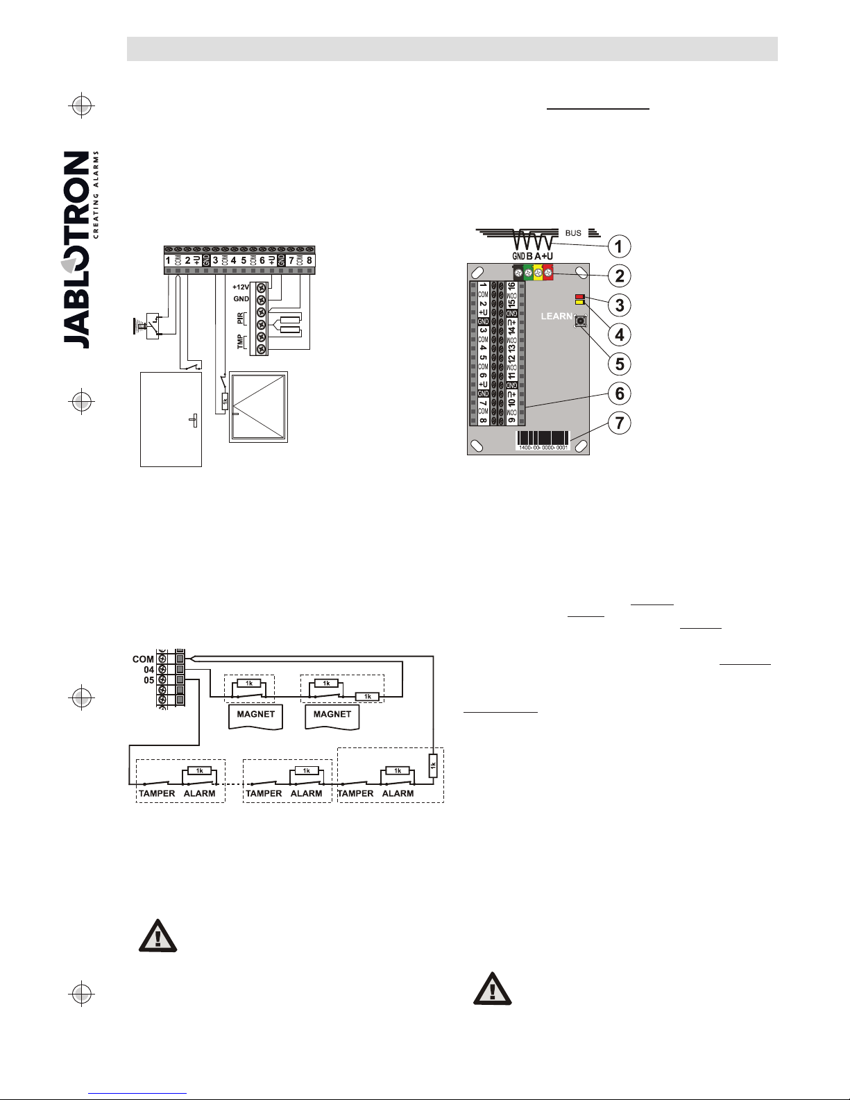
Figure: Loop connection
example
The mode of the
connection is selectable
for every input
individually using F-Link
sw in the module
Internal settings.
xZones can be connected as NO (example: 1-COM), as NC
(example: 2- COM), as a single balanced loop (example: 3-COM)
or as a double balanced loop (example: 8-COM).
Activation by repeated pulses (e.g. a roller blind) is available for
input terminals 1 to 8.
xBalancing resistors for single and double balancing are
selectable from these: 1k, 2k2, 3k3, 4k7, 5k6, 10k. The
selection is common to all expander inputs. There are 32x 1k
resistors in the module accessories.
xYou are able to connect up to 5 devices (magnetic, PIR, or
any other detectors) to one input terminal when you use a
double balanced zone with 1k resistors
xThe maximum length of a wired loop is 100m.
Figure: Example of wiring more detectors to one input terminal when the
loop is double balanced by 1k resistors. Connection of 2 magnetic
contacts to the 4-COM input terminals. Connection of detectors with
alarm and tamper contacts to the 5-COM input terminals.
3. When the module is mounted in an installation box, this box has to
be equipped with a tamper contact. For external tamper contact
connection, use any wired input terminal.
4. Connect the BUS cable.
When connecting the module to the system
BUS, always switch the power off.
5. Proceed according to the control panel installation manual. Basic
procedure:
a.When the device is connected, the yellow LED (4) starts flashing
repeatedly to indicate that the module has not been enrolled to the
system.
b.Go to the F-Link software, select the required position in the
Devices window and launch enrollment mode by clicking on the
Enroll button. Necessary condition: After the selected position,
the next 15 positions have to be free.
c. Press the LEARN button (5) – the module is enrolled into the 16
selected positions and the yellow LED goes off. Warning – the
module is enrolled to sixteen (16) consecutive positions (each input
is enrolled to one position). If some positions in those 15 are
already occupied, they will be overwritten. When there are not
enough positions at the end of the list of devices, only a limited
number of inputs will be enrolled to fill in the rest of the positions.
6. Close the installation box.
Figure:
1 – BUS cable;
2 – digital BUS terminals;
3 – red LED indicator;
4 – yellow LED indicator;
5 – LEARN (enroll) button;
6 – input terminals;
7 – production code
Note: Enrolling the module
to the system is possible by
entering the production
code (7) via F-link software
or by a production code
reader. All digits under the
production code are
required (1400-00-0000-
0001).
Module settings
The Internal settings option (at any module position) in the Devices
window in the F - Link software opens a dialog window where you can
set the following options for each output: (*factory settings):
LED activity indication: Enabled *:A short flash (3) indicates a
status change on any input (activation and deactivation).
Balanced inputs: The chosen value of balancing resistor R is
common for all terminals of the module. You can choose between 1k*,
2k2, 4k7, 5k6, or 10k. Valid for single and double balanced inputs.
Inputs 1 - 8 and Inputs 9 - 16: Disabled – no reaction (input is
completely disabled), Enabled * – input reacts to status change
connected to the input terminal (NC is standby), Balanced –contactis
connected in series with balancing resistor R (32 x 1k resistors are
available in the accessories). Activation happens if the resistance rises
or drops by more than 30% of the EOL resistor value, Rollerblind –
(inputs 1 - 8 only) reacts to short repeated pulses with sensitivity
adjustable to two levels: Impulse 1 = activation by 3 pulses up to max.
2 minutes; Impulse 2 = activation by 5 pulses up to max. 2 minutes.
Double balanced – standby: connection to COM via the EOL resistor R
(r20%), Activation: connection to COM via the EOL resistor 2R (r
30%), Tamper: connection to COM via EOL resistor lower than R –30%
or higher than 2R+30%.
Inverted input reaction: (valid for Enabled or Balanced input). The
default reaction is set to disconnection from COM (NC)*. By this you
can set the opposite reaction to grounding (NO).
Pulse mode: (valid for Enabled or Balanced input and inputs 1 to 8).
The default is a status reaction, the input reacts to activation
(disconnection from COM) and deactivation (connecting back to
COM)*. If you tick this option, the input will only react to disconnection
from COM (after 2s it returns to standby mode).
Delayed input reaction: a time filter for increasing the immunity and
to suppress false activations, 0.5 s* (options: 0.5s … 300 s). This tells
you how long the input has to be activated to trigger an alarm in the
control panel. It is possible to use the parameter with the input set as
enabled (options from 0.1s), balanced and double balanced.
Note: The expander faulty reports are recorded in the event memory
of the control panel. The source of these events is the 1st input position,
defined by enrolling.
The manufacturer only guarantees correct functioning
of the module. However, it cannot guarantee the
correct functioning of connected detectors. We
therefore strongly recommend using Jablotron JA-100
bus detectors.