manuals.online logo
Brands
  1. Home
  2. •
  3. Brands
  4. •
  5. jablotron
  6. •
  7. Home Safety Product
  8. •
  9. jablotron PG-4 Guard User manual

jablotron PG-4 Guard User manual

PG-4G 1/2 MEG52202
PG - 4 Guard
PG-4G is a 12-channel transceiver of panic signals transmitted from or
to other PG-4G units. The panic transmission can be triggered by the
remote controls (RC-11, RC-22, RC-28).
If the unit is triggered by the remote control it will send the signal to
other units that have been enrolled to the one, which is transmitting the
panic signal. The received signal is indicated by the corresponding LED
diode placed on the front panel of the unit. By the position of the active
LED diode is to be found from which unit (place) the signal was sent.
Activation can be also indicated by the built-in buzzer (depending on a
jumper BUZZER) or by an external siren, flashing light, telephone dialer
etc.
It also cooperates with a pocket receiver PG-4R. Every panic signal is
sent to all enrolled PG-4G units as well as to the receivers PG-4R.
Specification
Power supply: 12 V DC
Stand-by consumption: 55-100mA
Maximal supply current: 0,5 A
Max output load: 12 V, max. 250mA
Output OUT for TD-101connection 12 V, max. 5mA
Dimensions: 188 x 135 x 40 mm (without antenna)
Working environment: indoor use (class II)
Working temperature: -10 to +40oC
Built-in receiver of the remote controls
Compatible remote controls: RC-11, RC-22, RC-28
Number of controllers: up to 30
Coding: digital, each remote control has a unique floating code
Working distance: depending on the remote control -
Max 100m open area
Operating frequency: 433.9 MHz, ISM EN 300220
Built-in receiver/transmitter for communication with other units
PG-4G
Number of cooperating units: up to 13
Coding: digital
Working distance: up to 2 km (open area)
Operating frequency: 448.17 MHz
Transmitting time 3 sec.
Radiated power 0.5 W
External antenna (optional) Yes, type AN-01A, AN-02, AN-03
Wireless local indication of the activation (optional)
Compatible receivers: PG-4R, PG-4M
Number of receivers: unlimited
Working distance: up to 2 km (open area)
In Norway and Belgium can be operated according to ERC REC 70-03
as e SRD.
Hereby, Jablotron Ltd. declares that this PG-4G is in compliance with
the essential requirements and other relevant provisions of Directive
1999/5/EC.
Original of the conformity assessment can be found at the web page
www.jablotron.cz, section Technical support.
Note: Although this product does not contain any harmful materials we
suggest you to return the product to the dealer or directly to the
producer after usage.
Installation
The metal case should be installed on a wall with its antenna in a
vertical position. The unit should not be installed close to any metal
structures or other objects obstructing radio signal transmission.
Route the wires through the hole in the rear part of the housing. Attach
the case to the desired place using the provided screws.
Terminal description:
+12V, GND DC power input 12 V DC
OUT Output for a telephone dialer (TD-101) activation,
connected to ground in case of the alarm, max. load 5mA)
SIR output for external indication 12V / 250mA max, timeout
60 minutes
+U, GND DC power output 12 V DC 100mA max
Indicators and controllers for installation/service
The indicators 1-12 on the cover indicate the status of the unit during
the learning mode. Buttons and (up or down) are used to
control the learning mode (see figure 1).
figure 1
Other controlling buttons/jumpers are placed on the main board (see
figure 2):
TRA N SM I TER
REC EIVER
BUZZER
JP4
ANT
JP1
LEARN
TRA N SM I T
TEST
EXP
RS 2 3 2
+ U
GND
OUT
SIR
+12V
GND
A D RESS
figure 2
Button LEARN to enroll the remote controls
LED LEARN indicates opening of the enrollment mode
LED TEST indicates activation of enrolled remote control in
the test mode (JP1)
Button TRANSMIT to transmit the enrolling signal to other PG-4G
units
LED TRANSMIT indicates the transmission of PG-4G
Jumper JP1 right position – if the unit is triggered by the panic
button it will start transmitting to other PG-4G
units as well as to the local receivers PG-4R if
there are any
left position – if the unit is triggered by the panic
button it will start transmitting only to other PG-
4G receivers
Jumper JP4 Close upper and middle pins to test the remote
controls
Open – normal function
Jumper BUZZER Close – to switch ON the built-in buzzer
Open – to switch OFF the built-in buzzer
RS-232 connector for PC connection (RS-232)
ANT AN-01A external antenna connector (when AN-
01A is used, the rod antenna must be
disconnected)
EXP connector for external communication
Recommended procedure of setting
1. First of all enroll the remote controls to each unit.
2. If any receivers PG-4R (M) are used enroll them after that.
3. Enroll other PG-4G units.
PG-4G 2/2 MEG52202
When any other remote control or receiver PG-4R is being enrolled
the panic signal will be transmitted to all cooperating units. Please
do not forget to announce it to all cooperating units prior to any
action.
1. Enrolment of the remote controls
By pressing the LEARN button open the learning mode. Flashing LED
diode LEARN indicates the learning mode. Press the button on the
remote control. Correct enrollment is indicated by a long shining of the
LED diode LEARN. The learning mode is closed automatically. If it is
needed to enroll another remote control the learning mode must be
open by the LEARN button again.
Notes:
•A newly enrolled RC button is added to previously enrolled ones
•When 30 remote controls are enrolled no other remote can be
added
•Double flashing of the LED indicates a full memory
•A learning mode will be closed when an RC button is enrolled,
or automatically after 10 seconds.
•When the power is disconnect the codes of the remote controls
will remain in the memory
Test of the remote controls:
By closing the jumper TEST (upper and middle PIN) the unit will be
switched to the special testing mode. In this mode the reaction to the
signal from the remote controls will be audible (built-in buzzer) but it will
not transmit any signal to other units.
Note: during normal operation period the jumper TEST must
remain open otherwise no panic signal will be sent.
Erasing of the remote controls:
Press the button LEARN to open the learning mode. Press and hold the
LEARN button for 5s to erase all the remote controls – confirmed by 4
quick flashes of LED diode LEARN.
2. Enrolment of the pocket receiver PG-4R
For local indication of the panic signal the pocket receiver PG-4R or
PG-4M can also be used. The receiver is activated by transmission
from any units PG-4G (depending on position of jumper JP1 also from
the local unit).
Press and hold the button on the receiver when installing the battery.
After about 5 seconds you will hear an acoustic signal and the indicator
will start flashing (learning mode).
Press the TRANSMIT button inside of the PG-4G unit to transmit the
learning signal.
Number of attached receivers PG-4R/M is unlimited.
3. Enrolment of other PG-4G units
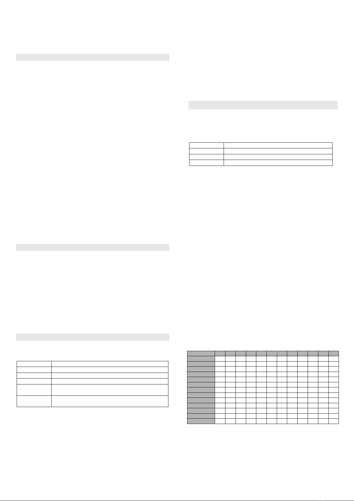
LED diodes 1 to 12 are used for better orientation in the learning mode
(see tab. 1).
LED 1 - 12
Description
Off
Channel is not used (no transmitter is enrolled)
Flashing Red
Learning mode to enroll a unit
Steady Green
Channel has a unit enrolled (no activation)
Flashing
Green / Red
Selected channel is already occupied
Light Red
For 1s
Channel has been activated by cooperating unit
tab. 1
Enrollment of other PG-4G units
Using button or (up or down) open the learning mode and select
desired position (current channel will be indicated by its LED diode
flashing). By pressing the TRANSMIT button or previously enrolled
remote control activate the PG-4G unit, which you want to enroll.
Enrolment will be confirmed by a shining LED diode for 1s following by
automatic closing of the learning mode.
Erasing of enrolled units
•Using button or (up or down) open the learning mode and
select the desired position (LED diode is flashing-Red/Green).
•Press RESET on the front panel.
Notes:
•Only one unit can be enrolled to each channel
•If it is needed to change the position of any unit it must be
erased from its original position first.
•Timeout of learning mode is 5 minutes
•When the power is disconnect the codes of other units will
remain in the memory
Operation
The green LED AC indicates presence of the power supply.
LED diodes 1 to 12 indicate the status of other enrolled units (see tab. 2):
LED 1 - 12
Description
Off
Channel is not used (no transmitter is enrolled)
Steady Green
Channel has a transmitter enrolled (no activation)
Steady Red
Channel has been activated
tab. 2
When the panic signal is received it will be indicated by:
•A red light of corresponding LED diode
•An audible signal from built-in buzzer (if the jumper
BUZZER is closed)
•An external device connected to the contact SIR
(12V/250mA) – this output will be deactivated in 60 minutes
or when the button RESET is pressed
•An external device connected to the contact OUT
(12V/5mA max) – this output will be deactivated in 1 minute
•Local receiver PG-4R (if there is any and depending on
setting of jumper JP4)
The reset button placed on the cover is used for confirmation of
received signals.
When the unit is triggered by the remote control the panic signal will
be sent immediately to all cooperating units as well as to the local
receiver PG-4R (if there is any and depending on setting of jumper
JP4) but it will not cause any obvious reaction directly on the unit,
which has been triggered.
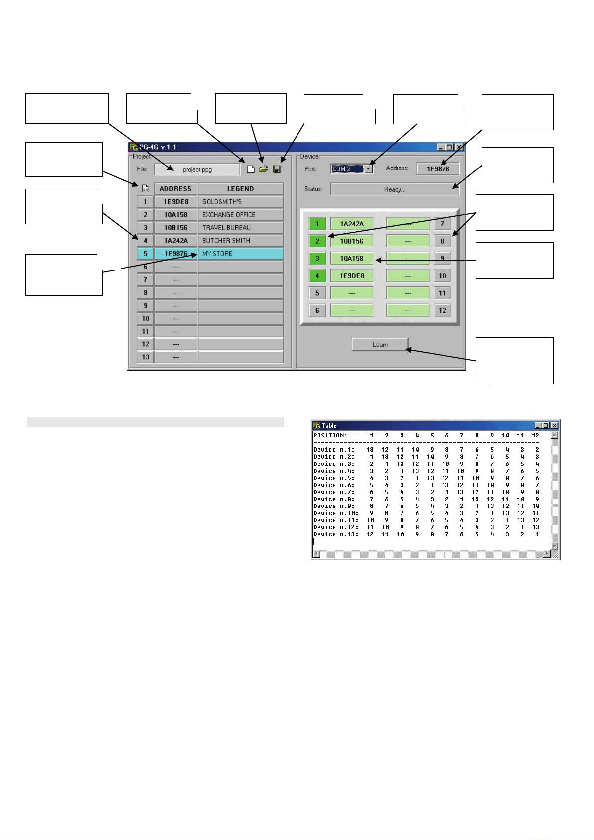
For more reliable transmissions between the cooperating units there
is a delay of each transmission based on enrolled position of the
units. This delay assures that the units will not start transmitting at
the same time. Also the reaction of the pocket receivers PG-4R will
slightly vary (approximately 30seconds depending on number of PG-
4G units in the set). For that reason it is recommended to enroll every
unit according to table 3 (each unit must be enrolled at different
position).
If the enclosed setting software is used it will be done automatically.
Position
1
2
3
4
5
6
7
8
9
10
11
12
PG-4G n.1
13
12
11
10
9
8
7
6
5
4
3
2
PG-4G n.2
1
13
12
11
10
9
8
7
6
5
4
3
PG-4G n.3
2
1
13
12
11
10
9
8
7
6
5
4
PG-4G n.4
3
2
1
13
12
11
10
9
8
7
6
5
PG-4G n.5
4
3
2
1
13
12
11
10
9
8
7
6
PG-4G n.6
5
4
3
2
1
13
12
11
10
9
8
7
PG-4G n.7
6
5
4
3
2
1
13
12
11
10
9
8
PG-4G n.8
7
6
5
4
3
2
1
13
12
11
10
9
PG-4G n.9
8
7
6
5
4
3
2
1
13
12
11
10
PG-4Gn.10
9
8
7
6
5
4
3
2
1
13
12
11
PG-4Gn.11
10
9
8
7
6
5
4
3
2
1
13
12
PG-4Gn.12
11
10
9
8
7
6
5
4
3
2
1
13
PG-4Gn.13
12
11
10
9
8
7
6
5
4
3
2
1
tab. 3table of the enrolled position of the PG-4G units
PG-4G 3/2 MEG52202
Description of the setting software PG-4G
Adjusting of the PG-4G set using the software
1. Run PG-4G software and set a new project.
2. Insert the addresses of all cooperating units PG-4G, which can be
found on the paper label sticked onto the transmitter.
3. Insert name / description where the units will be placed.
4. Save the project.
5. Set the correct COM port. Connect PG-4G unit to the power
supply and to the computer. If the connection is successful the
word “Ready…” will appear in the field Status.
6. When the unit, which address has been already filled in is
connected the button “LEARN” will be enabled.
7. By pressing button LEARN all the addresses according to table 4
will be enrolled to the connected unit.
Points 5, 6 and 7 repeat for each unit.
tab. 4 table of the enrolled position of the PG-4G units.
Name of opened
project
To set a new
project
To open the
existing project
To save the
project
To set the
COM port
Address of the
connected PG-
4G unit
Status of the
communication
Status of the
cooperating PG-
4G units
Addresses of the
cooperating PG-
4G units
Button for
configuration of
the connected
PG-4G units
To show the
enrollment table
see tab. 4
To set address
of PG-4G units
Name /
description of
PG-4G units
7.
1.
3.
4.
5.
2.

Popular Home Safety Product manuals by other brands

CareTech Grace+ Service manual / technical handbook

CareTech

CareTech Grace+ Service manual / technical handbook

Heath Zenith Motion Sensor Entryway Light SL-5610/15 owner's manual

Heath Zenith

Heath Zenith Motion Sensor Entryway Light SL-5610/15 owner's manual

Fire Chief Stove Guard SGS1010 Installation & operating instructions

Fire Chief

Fire Chief Stove Guard SGS1010 Installation & operating instructions

Heath Zenith DualBrite Motion Sensor Light Control 2LBL3 Operating instructions and parts manual

Heath Zenith

Heath Zenith DualBrite Motion Sensor Light Control 2LBL3 Operating instructions and parts manual

Sprue Safety Products SONA SGEL-SN-1 Guide

Sprue Safety Products

Sprue Safety Products SONA SGEL-SN-1 Guide

Timago JMC-C 5300KD user manual

Timago

Timago JMC-C 5300KD user manual

Qdos Construct-A-SafeGate user guide

Qdos

Qdos Construct-A-SafeGate user guide

Philips LRM 8112 Specification sheet

Philips

Philips LRM 8112 Specification sheet

Visonic SD-304 PG2 Specifications

Visonic

Visonic SD-304 PG2 Specifications

Niko 10-575 user manual

Niko

Niko 10-575 user manual

manuals.online logo
manuals.online logoBrands
  • About & Mission
  • Contact us
  • Privacy Policy
  • Terms and Conditions

Copyright 2025 Manuals.Online. All Rights Reserved.