IMS MDO17Plus User manual

17 TM
SPEED CONTROL
TM
DESCRIPTION
The MDrive17Plus Speed Control offers
system designers cost effective, program-
mable velocity control integrated with a
NEMA 17 high torque 1.8° brushless step
motor and a +12 to +48 volt microstepping
driver.
The MDrive17Plus Speed Control features
a digital oscillator for accurate velocity
control with an output frequency of up
to 5 Megahertz. Output frequency will
vary with the signal applied to the speed
control input and can be limited by the
amount specified by the Maximum Veloc-
ity parameter.
Speed can be adjusted using three modes
of operation: voltage, current and PWM.
The ranges are 0 to +5 volts and 0 to
+10 volts in voltage mode, 0 to 20 mA
and 4 to 20 mA in current mode, and 15
to 25 kHz in PWM mode. This allows the
MDrive17Plus Speed Control to be driven
by a wide variety of sensors and control
devices.
There are two basic methods for control-
ling the velocity: bidirectional and unidi-
rectional. By moving the center point, both
speed and direction are controlled by a
potentiometer or joystick. By setting the
center point to zero or the lower end of the
potentiometer, only velocity is controlled
by the speed control input; direction is
controlled by a separate digital input.
The MDrive17Plus Speed Control has 18
setup parameters, which may be con-
figured using the supplied IMS Analog
Speed Control GUI, or a user-developed
front-end communicating over SPI. The
setup parameters enable the user to con-
figure all MDrive operational parameters
which are stored in nonvolatile memory.
The versatile, compact MDrive17Plus
Speed Control is available in multiple
FEATURES
• Highly Integrated Microstepping Driver,
Intelligent Variable Speed Controller and
NEMA 17 High Torque 1.8° Brushless
Step Motor
• Advanced 2nd Generation Current
Control for Exceptional Performance and
Smoothness
• Single Supply: +12 to +48 VDC
• Cost Effective
• Extremely Compact
• 20 Microstep Resolutions up to
51,200 Steps Per Rev Including:
Degrees, Metric, Arc Minutes
• 10-bit Analog Speed Control Input
Accepts:
- 0 to +5 VDC
- 0 to +10 VDC
- 4 to 20 mA
- 0 to 20 mA
- 15 to 25 kHz PWM
• Automatic Current Reduction
• Electronically Configurable:
- Motor Run/Hold Current
- Microstep Resolution
- Acceleration/Deceleration
- Initial and Max Velocity
- Hold Current Delay Time/Motor
Settling Delay Time
- Programmable Filtering for the
Start/Stop Input
• Available Options:
- Long Life Linear Actuators**
- External Optical Encoder
- Integrated Planetary Gearbox
- Control Knob for Manual Positioning
- Linear Slide
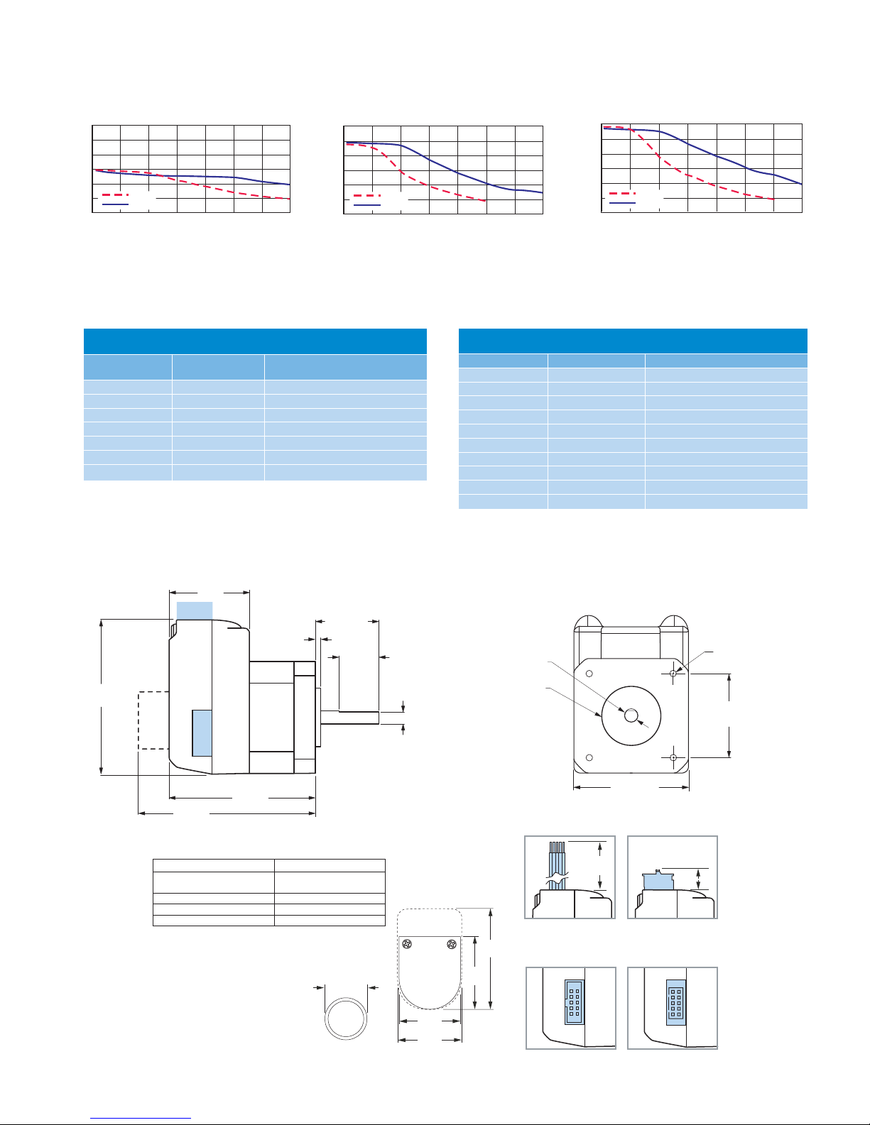
• 3 Rotary Motor Lengths Available
• Setup Parameters May Be Switched
On-The-Fly
• Interface Options:
- Pluggable Terminal Strip
- 12.0” (30.5cm) Flying Leads
• Graphical User Interface (GUI) for Quick
and Easy Parameter Setup
** Consult Factory for Availability.
www.imshome.com
configurations to fit various system needs.
Rotary motor versions come in three
lengths and may include an optical en-
coder, control knob, planetary gearbox or
linear slide. Long life Acme screw linear
actuators** are also available.
Connector style options give you choices
for the best fit and features. Select from
12.0" (30.5cm) flying leads or pluggable
terminal strip.
MDrivePlus connectivity has never been
easier with options ranging from all-inclu-
sive QuickStart Kits to individual inter-
facing cables and mating connector kits
to build your own cables. See pg 4.
The MDrive17Plus is a compact, powerful
and cost effective motion control solution
that will reduce system cost, design and
assembly time for a large range
of brushless step motor applications.
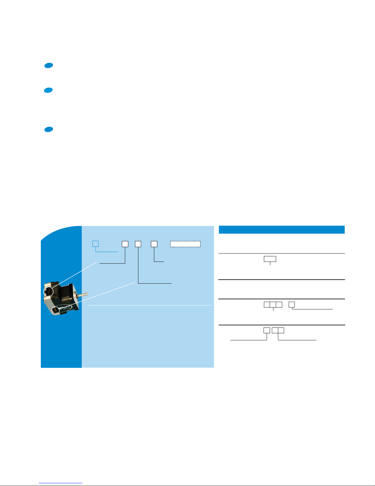
CONFIGURING
The IMS Analog Speed Control is a soft-
ware GUI for quick and easy parameter
setup of the MDrivePlus Speed Control
from a computer's USB port. GUI ac-
cess is via the IMS SPI Motor Interface
available at www.imshome.com. The IMS
interface is also used to upgrade MDrive-
Plus Speed Control firmware.
IMS Analog Speed Control features:
• Easy installation.
• Automatic detection of MDrivePlus ver-
sion and communication configuration.
• Will not set out-of-range values.
• Tool-tips display valid range setting for
each option.
• Simple screen interface.
Excellence in Motion
new

2 MDrive17Plus Speed Control REV060208
Holding Torque Detent Torque Rotor Inertia Weight (Motor+Driver)
SINGLE LENGTH 32 oz-in / 22.6 N-cm 1.66 oz-in / 1.17 N-cm 0.00053
oz-in-sec
2
/ 0.038
kg-cm
2
10.4 oz / 294.8 g
DOUBLE LENGTH 60 oz-in / 42.4 N-cm 2.08 oz-in / 1.47 N-cm 0.00080
oz-in-sec
2
/ 0.057
kg-cm
2
12.0 oz / 340.2 g
TRIPLE LENGTH 74.9 oz-in / 52.9 N-cm 3.47 oz-in / 2.45 N-cm 0.00116
oz-in-sec
2
/ 0.082
kg-cm
2
15.2 oz / 430.9 g
Optional encoder cables are available.
MOTOR SPECIFICATIONS
ENCODER SPECIFICATIONS
DIFFERENTIAL ENCODER
with locking connector feature
SINGLE-END
ENCODER
Encoder Function Function
Pin 1 No Connect Ground
Pin 2 +5 VDC Input Index
Pin 3 Ground Channel A
Pin 4 No Connect +5 VDC Input
Pin 5 Channel A – Channel B
Pin 6 Channel A +
Pin 7 Channel B –
Pin 8 Channel B +
Pin 9 Index –
Pin 10 Index +
Line Counts and Part Numbers
Pin Assignments
DIFFERENTIAL ENCODER
with locking connector feature
SINGLE-END
ENCODER
Line Count Part Number Part Number
100
EAL
E1
200
EBL
E2
250
ECL
E3
256 EWL EP
400
EDL
E4
500
EHL
E5
512 EXL EQ
1000
EJL
E6
1024 EYL ER
MDrive
17Plus
SPEED CONTROL
INPUT VOLTAGE (+V) Range
+12 to +48 VDC
Power supply current requirements = 2A (maximum) per MDrive17Plus.
Actual power supply current will depend on voltage and load.
SPEED CONTROL
Input 0 to +5 VDC*, 0 to +10 VDC, 4 to 20 mA, 0 to 20 mA or 15 to 25 kHz PWM
A/D Resolution 10 bit
LOGIC INPUT
Start/Stop and Direction
Low Level 0 to +0.8 VDC
High Level +2.0 to +5.0 VDC
Internal Pull-up Resistance (to +3.3 VDC)
20 kΩ
MOTION
Oscillator Frequency (Max) 5 MHz
Microstep Resolution
Number of Settings 20
Steps Per Revolution
200,
400, 800, 1000, 1600, 2000, 3200, 5000,
6400, 10000, 12800, 20000, 25000, 25600,
40000, 50000, 51200, 36000 (0.01 deg/µstep),
21600 (1 arc minute/µstep), 25400 (0.001mm/µstep)
THERMAL Operating Temperature Heat Sink –40° to +85°C (non-condensing)
Motor –40° to +100°C (non-condensing)
*10 kΩpotentiometer resistance.
STANDARD SPECIFICATIONS
SETUP PARAMETERS
Function Range Units Default
A1 Analog Input Mode 0 to +5 VDC, 0 to +10 VDC,
4 to 20 mA, 0 to 20 mA, 15 to 25 kHz PWM — 0 to +5 VDC
ACCL Acceleration 91 to 1.5 X 10
9steps/second
21,000,000
CJoystick Center 1 to 1022 counts 0
DB Analog Deadband 0 to 255 counts 1
DECL Deceleration 91 to 1.5 X 10
9steps/second
21,000,000
DIR Motor Direction Override Clockwise (CW) / Counterclockwise (CCW) — CW
FAULT Fault/Checksum Error Error Code — None
FS Analog Full Scale 1 to 1023 counts 1023
HCDT Hold Current Delay Time HCDT + MSDT <= 65535 milliseconds 500
IF Analog Input Filter 1 to 1000 counts 1
MHC Motor Hold Current 0 to 100 percent 5
MRC Motor Run Current 1 to 100 percent 25
MSDT Motor Settling Delay Time MSDT + HCDT <= 65535 milliseconds 0
MSEL Microstep Resolution 1, 2, 4, 5, 8, 10, 16, 25, 32, 50, 64, 100,
108, 125, 127, 128, 180, 200, 250, 256 µsteps per full step 256
SSD Stop/Start Debounce 0 to 255 milliseconds 0
VI Initial Velocity 0 to <VM steps/second 1000
VM Maximum Velocity VI to 5,000,000 steps/second 768,000
USER ID User ID Customizable 1–3 characters IMS
All parameters are set using the supplied IMS SPI Motor Interface GUI and may be changed on-the-fly.
An optional Communication Converter is recommended with first orders.

MDrive17Plus Speed Control REV060208 3
WIRE/PIN ASSIGNMENTS — MDrive17Plus Speed Control
P1: I/O & POWER CONNECTOR
Pluggable
Terminal Strip
Flying Leads
Wire Colors Function
Pin 1 Violet Start/ Stop Input
Pin 2 Blue CW/CCW Direction Input
Pin 3 Green Speed Control Input
Pin 4 Yellow +5 VDC Output
Pin 5 Gray Logic Ground
Pin 6 Black Power Ground
Pin 7 Red +V (+12 to +48 VDC)
MOTOR PERFORMANCE — Speed-Torque
Single Length Rotary Motor Double Length Rotary Motor Triple Length Rotary Motor
Torque in Oz-In
T
orque
i
n
N
-cm
S
p
eed in Full Ste
p
s
p
er Second
(
RPM
)
01000 2000 3000 4000 5000 6000 7000
(300) (600) (900) (1200) (1500) (1800) (2100)
50
60
40
30
20
10
0
35
42
28
21
14
7
24 VDC
48 VDC
Torque in Oz-In
Torque in N-cm
Speed in Full Steps per Second (RPM)
01000 2000 3000 4000 5000 6000 7000
(300) (600) (900) (1200) (1500) (1800) (2100)
50
60
40
30
20
10
0
24 VDC
48 VDC
42
35
28
21
14
7
Torque in Oz-In
T
orque
i
n
N
-cm
S
p
eed in Full Ste
p
s
p
er Second
(
RPM
)
01000 2000 3000 4000 5000 6000 7000
(300) (600) (900) (1200) (1500) (1800) (2100)
50
60
40
30
20
10
0
35
42
28
21
14
7
24 VDC
48 VDC
P2: COMM CONNECTOR (SPI)
10-Pin IDC 10-Pin Wire Crimp Function
Pin 1 Pin 9 No Connect
Pin 2 Pin 10 No Connect
Pin 3 Pin 7 No Connect
Pin 4 Pin 8 SPI Chip Select
Pin 5 Pin 5 Communications Ground
Pin 6 Pin 6 +5 VDC Output
Pin 7 Pin 3 SPI Master Out – Slave In
Pin 8 Pin 4 SPI Clock
Pin 9 Pin 1 No Connect
Pin 10 Pin 2 SPI Master In – Slave Out
Ø 0.866 +0/-0.002
(Ø 21.996 +0/-0.051)
Ø 0.1968 +0/-0.0005
(Ø 4.999 +0/-0.013)
1.68 SQ.
(42.7 SQ.)
1.220 ±0.004 SQ.
(31.0 ±0.1 SQ.)
4X M3x0.5 THREAD
x0.15 MIN DEEP
P1
Connector
Option
2.30
(58.3) P2
1.19
(30.2)
LMAX2
LMAX
0.177 ±0.002
(4.49 ±0.05)
0.08
(2.0)
0.94 ±0.02
(23.9 ±0.5)
0.59 ±0.02
(15.0 ±0.5)
Connector
Option
MECHANICAL SPECIFICATIONS
Dimensions in Inches (mm)
LMAX LMAX2
Motor
Length
SINGLE SHAFT or LINEAR
ACTUATOR VERSION
CONTROL KNOB or
ENCODER VERSION
Single 2.20 (55.9) 2.79 (70.9)
Double 2.43 (61.7) 3.02 (76.7)
Triple 2.77 (70.4) 3.37 (85.6)
MDrive Lengths Inches (mm)
Ø 0.97
(Ø 24.6)
Control Knob
1.20
(30.4)
1.42
(36.1)
2.04*
(51.8)
Differential
Encoder*
.
1.22*
(31.0)
.
Single-End
Encoder
Encoder
LMAX2 Options
0.44
(11.2)
P1
12.00+1.0/-0.0
(304.8+25.4/-0.0)
P1
P1 Connector Options
7-Pin Pluggable Clamp
Type Terminal Strip
Flying Leads
P2
P2 Connector Options
10-Pin IDC
P2
10-Pin Friction Lock
Wire Crimp
Connectivity details:
www.imshome.com/cables_cordsets.html
I/O & Power I/O & Power
Comm Comm

(inches/rev)
A = 0.10” (2.54mm)
B = 0.20” (5.08mm)
C = 0.50” (12.7mm)
D = 1.00” (25.4mm)
–R
Screw Lead Standard Screw Lengths
10", 12", 15", 18", 24" or 36"
For Custom Lengths, Consult Factory
Linear
Slide
Example: MDO1PSD17A4–RA10 adds a Linear Slide with
0.10" screw lead, 10" long to example #1.
NOTE: 10" lengths only with A or B leads.
15" lengths only with A, B or C leads.
36" lengths only with D leads.
Example #1: Part Number MDO1PSD17A4
is an MDrive17Plus
Speed
Control
with pluggable I/O & power interface, SPI communications with
10-pin IDC connector, and NEMA 17 single length motor.
–N
–E
External
Encoder
Control
Knob
Example: MDO1PSD17A4–N adds a rear control knob for manual
positioning to example #1.
Refer to encoder specifications section for line counts and part numbers.
OPTIONS
– G
Planetary
Gearbox
Example: MDO1PSD17A4–G1A2 adds a 1-stage planetary gearbox
with 5.18:1 ratio to example #1. Add –F for optional NEMAflange.
– F Optional NEMA Flange
Refer to gearbox page for complete table of ratios and part numbers.
Example: MDO1PSD17A4–EHL adds an external 500-line count
differential optical encoder with index mark to example #1.
For complete product specifications, see:
www.imshome.com/mdriveplus_linear_actuator.html
–L
Linear
Actuator**
Plus
base version
**Consult Factory for Availability.
B = Double Length
C = Triple Length
OPTION
P1: I/O & Power
F = 12" Flying Leads
P = Pluggable Clamp
Type Terminal Strip
P2: Communications
D =SPI with 10-Pin IDC Connector
L = SPI with 10-Pin Friction Lock Wire
Crimp Connector
A = Single Length & Linear Actuator**
MDO1 S
17 4
–
Motor
QuickStart Kit
details above
K
ORDER INFORMATION — MDrive17Plus Speed Control
CONNECTING
QuickStart Kit
For rapid design verification, all-inclusive QuickStart Kits have com-
munication converter, prototype development cable(s), instructions
and CD for MDrivePlus initial functional setup and system testing.
Communication Converters
Electrically isolated, in-line converters pre-wired with mating connec-
tors to conveniently set/program communication parameters for a
single MDrivePlus via a PC's USB port. Length 12.0' (3.6m).
Mates to connector:
10-Pin IDC ............................................MD-CC300-001
10-Pin Wire Crimp .................................MD-CC302-001
Mating Connector Kits
Use to build your own cables. Kit contains 5 mating shells with pins.
Cable not supplied. Manufacturer's crimp tool recommended.
Mates to connector:
10-Pin Wire Crimp .................................CK-02
Kit contains 5 mating connectors that press fit onto ribbon cable.
Cable not supplied.
10-Pin IDC ............................................CK-01
OPTIONS
Linear Actuator**
The MDrive17Plus is offered with numerous linear actuator
styles and options to satisfy a broad range of linear motion
applications. Contact the factory for details or see:
www.imshome.com/mdriveplus_linear_actuator.html
External Encoder
External optical encoders, single-end or
differential
, are
offered factory-mounted with the MDrive17Plus. Refer
to the Encoder Specifications section for available line
counts. All encoders come with an index mark.
Optional encoder cables are available. Order separately.
Single-end Cable (12.0"/30.5cm)............ES-CABLE-2
Differential Locking Cable (6.0'/1.8mm)......ED-CABLE-6
Control Knob
The MDrive17Plus Speed Control is available with a factory-
mounted rear control knob for manual shaft positioning.
Planetary Gearbox
Efficient, low maintenance planetary gearboxes are
offered assembled with the MDrive17Plus. Refer to
details and part numbers on the back cover.
Linear Slide
Integrated linear slides are available factory installed for
precision linear movement. Screw leads are 0.1", 0.2", 0.5"
or 1.0" of travel per rev. Slides are 12.0" (30.5cm) to 36.0"
(91.44cm) long. Contact factory for custom lengths. Refer
to separate datasheet or web site for complete details.
PART NUMBERING
CONNECTIVITY OPTIONS
new
new
new
**Consult Factory for Availability.
Connectivity details: www.imshome.com/cables_cordsets.html
4 MDrive17Plus Speed Control REV060208

Permitted
Output Torque
(oz-in/Nm)
Gearbox
Efficiency
Maximum
Backlash
Output Side with Ball Bearing
Maximum Load
(lb-force/N)
Weight
(oz/g)
Radial Axial Gearbox with Flange
1-STAGE 425/3.0 0.80 0.80° 36/160 11/50 14.3/406 14.8/420
2-STAGE 1062/7.5 0.75 0.85° 52/230 18/80 17.9/508 18.5/525
3-STAGE 2124/15.0 0.70 0.90° 67.5/300 25/110 18.5/525 22.2/630
Planetary Gearbox for MDrive17Plus
Dimensions in Inches (mm)
Key DIN 6885-A-3x3x16mm
Ctrg.DIN 332-DM3
*Gearbox without Flange
†
Gearbox with Flange
0.08
(2.0)
Ø 0.315 +0/-0.0004
(Ø 8.0 +0/-0.009)
Ø 0.984* or 0.866†
(Ø 25.0* or 22.0†)
+0/-0.002 (+0/-0.052)
0.984*
(25.0)
or
0.846
†
(21.5) k1 ±0.02 (±0.5)
Ø 1.654
(Ø 42.0)
1.20
(30.5)
M4 x 0.394 (10.0) Deep*
M3 x 0.394 (10.0) Deep*
Ø 1.26*
(Ø 32.0)
Ø 1.417*
(Ø 36.0)
1.657 SQ.
(42.1 SQ.)
1.22
†
(31.0)
M3 x 0.276 (7.0) Deep
†
MDrive17Plus
Planetary Gearbox Parameters
Gearbox Lengths Inches (mm)
k1
GEARBOX* with FLANGE†
1-Stage 2.736 (69.5) 2.858 (72.6)
2-Stage 3.248 (82.5) 3.37 (85.6)
3-Stage 3.76 (95.5) 3.882 (98.6)
© Intelligent Motion Systems, Inc. All Rights Reserved. REV060208
IMS Product Disclaimer and most recent product information at www.imshome.com.
The MDrive17Plus is available with a Planetary Gearbox option developed to increase torque at lower speeds, enable better inertia
matching and produce finer positional resolutions. These efficient, low maintenance Planetary Gearbox come fully assembled with
the MDrive and are offered in a large number of reduction ratios in 1-, 2- and 3-stage configurations. An optional NEMA Output
Flange allows mounting the Planetary Gearbox to the load using a standard NEMA bolt circle. Planetary Gearbox may be combined
with other MDrive17Plus options, however are unavailable with Linear Actuators.
MDRIVE17PLUS WITH PLANETARY GEARBOX
Ratios and Part Numbers
Planetary
Gearbox
Ratio
(Rounded)
Part
Number
**
1-Stage 3.71:1 G1A1
1-Stage 5.18:1 G1A2
1-Stage 6.75:1 G1A3
2-Stage 13.73:1 G1A4
2-Stage 15.88:1 G1A5
2-Stage 18.37:1 G1A6
2-Stage 19.20:1 G1A7
2-Stage 22.21:1 G1A8
2-Stage 25.01:1 G1A9
2-Stage 26.85:1 G1B1
2-Stage 28.93:1 G1B2
2-Stage 34.98:1 G1B3
2-Stage 45.56:1 G1B4
3-Stage 50.89:1 G1B5
3-Stage 58.86:1 G1B6
3-Stage 68.07:1 G1B7
3-Stage 71.16:1 G1B8
3-Stage 78.72:1 G1B9
3-Stage 92.70:1 G1C1
3-Stage 95.18:1 G1C2
3-Stage 99.51:1 G1C3
3-Stage 107.21:1 G1C4
3-Stage 115.08:1 G1C5
3-Stage 123.98:1 G1C6
3-Stage 129.62:1 G1C7
3-Stage 139.14:1 G1C8
3-Stage 149.90:1 G1C9
3-Stage 168.85:1 G1D1
3-Stage 181.25:1 G1D2
3-Stage 195.27:1 G1D3
3-Stage 236.10:1 G1D4
3-Stage 307.55:1 G1D5
**Include optional planetary gearbox by adding –G plus
3 characters to the end of an MDrive part number.
Intelligent Motion Systems, Inc.
370 North Main Street, P.O. Box 457
Marlborough, CT 06447 - U.S.A.
Tel. +00 (1) 860 295-6102 - Fax +00 (1) 860 295-6107
e-mail: [email protected]
http: //www.imshome.com
U.S.A. SALES OFFICES
Eastern Region
Tel. 862 208-9742 - Fax 973 661-1275
e-mail: [email protected]
Central Region
Tel. 260 402-6016 - Fax 419 858-0375
e-mail: [email protected]
Western Region
Tel. 602 578-7201
e-mail:
IMS ASIA PACIFIC OFFICE
30 Raffles Pl., 23-00 Caltex House
, Singapore 048622
Tel. +65/6233/6846 - Fax +65/6233/5044
e-mail: [email protected]
IMS EUROPEAN SALES MANAGEMENT
4 Quai Des Etroits
69005 Lyon, France
Tel. +33/4 7256 5113 - Fax +33/4 7838 1537
e-mail: [email protected]
IMS UK Ltd.
Sanderson Centre, 15 Lees Lane
Gosport, Hampshire PO12 3UL
Tel. +44/0 2392-520775 - Fax +44/0 2392-502559
e-mail: [email protected]
TECHNICAL SUPPORT
Tel. +00 (1) 860 295-6102 - Fax +00 (1) 860 295-6107
e-mail: [email protected]
This manual suits for next models
1
Table of contents
Other IMS Home Safety Product manuals