shaped pockets and tighten it to form bowl mounting
studs. Position the square section O-ring in the O-ring
groove on the top of the base and place the china bowl on
the base in the desired orientation relative to the pump
assembly. Place one plastic washer (to protect the china),
then one stainles steel washer on each machine screw and
attach the remaining hex nuts to secure the bowl to the
base. Cap each machine screw and nut with a white deco-
rative nut cap.
Position the toilet assembly in its intended installed posi-
tion. When locating the toilet, ensure there is adequate
clearance above and to the rear of the bowl so the seat
and lid assembly can rotate slightly past vertical and will
remain up when lifted. Once the exact position for the toilet
has been determined, mark the location of the three
base attachment holes on the toilet mounting surface.
Determine the best toilet attachment method using 1/4"
(6 mm) fasteners (either machine screws for through
bolting or lag screws for topside attachment) and drill the
appropriate size holes for the fasteners being used. If secur-
ing the toilet with lag screws into a plywood underlayment
below fiberglass, be sure to drill a hole through just the fi-
berglass layer large enough to allow clearance for the
screw threads and shank to avoid cracking the fiberglass.
The PAR-MAX pump should be mounted to a solid
mounting surface. It should be secured with four fasteners
through the rubber grommets that snap into the pump’s
base. Do not over-tighten the mounting screws and crush
the grommets such that they will not absorb vibration.
The pump may be mounted in any position; however, if
mounting it to a vertical surface it should be oriented so
water dripping from a loose port connection will not drip
down on the motor. Plumbing runs should be kept as
short and straight as possible. All plumbing should
be completed with quality 3/4" (19 mm) hose that will not
collapse or kink. Route the inlet hose from a 3/4" (19 mm)
through hull and seacock fitting located well below the
waterline (and well forward of any discharge through
hulls, if installed) to the pump inlet port. Ensure the inlet
hose passes through an accessible location (preferably
above the vessel’s waterline) that will allow for the installation
of the Toilet Pumpgard strainer where it can be periodically
inspected and cleaned of debris. The Pumpgard strainer
should be secured with two fasteners to a solid mounting
surface with the flow arrow pointing towards the pump.
The inlet hose should be cut and each end attached to the
strainer’s ports. The hose from the strainer's discharge
port must connect with the PARMAX pump’s inlet port.
Provided with the toilet is a six foot length of smooth
white aesthetically pleasing hose to connect to the back
of the toilet bowl and be routed out of the head area.
Ideally, the PAR-MAX pump should be located so this
length of hose can be connected directly to the pump’s
discharge port avoiding an additional splice to the hose
leading from the pump to the back of the toilet bowl. If this
is not practical, acquire a 3/4" (19 mm) barb to barb hose
mender and splice the white hose to the supply hose
from the discharge port of the pump.
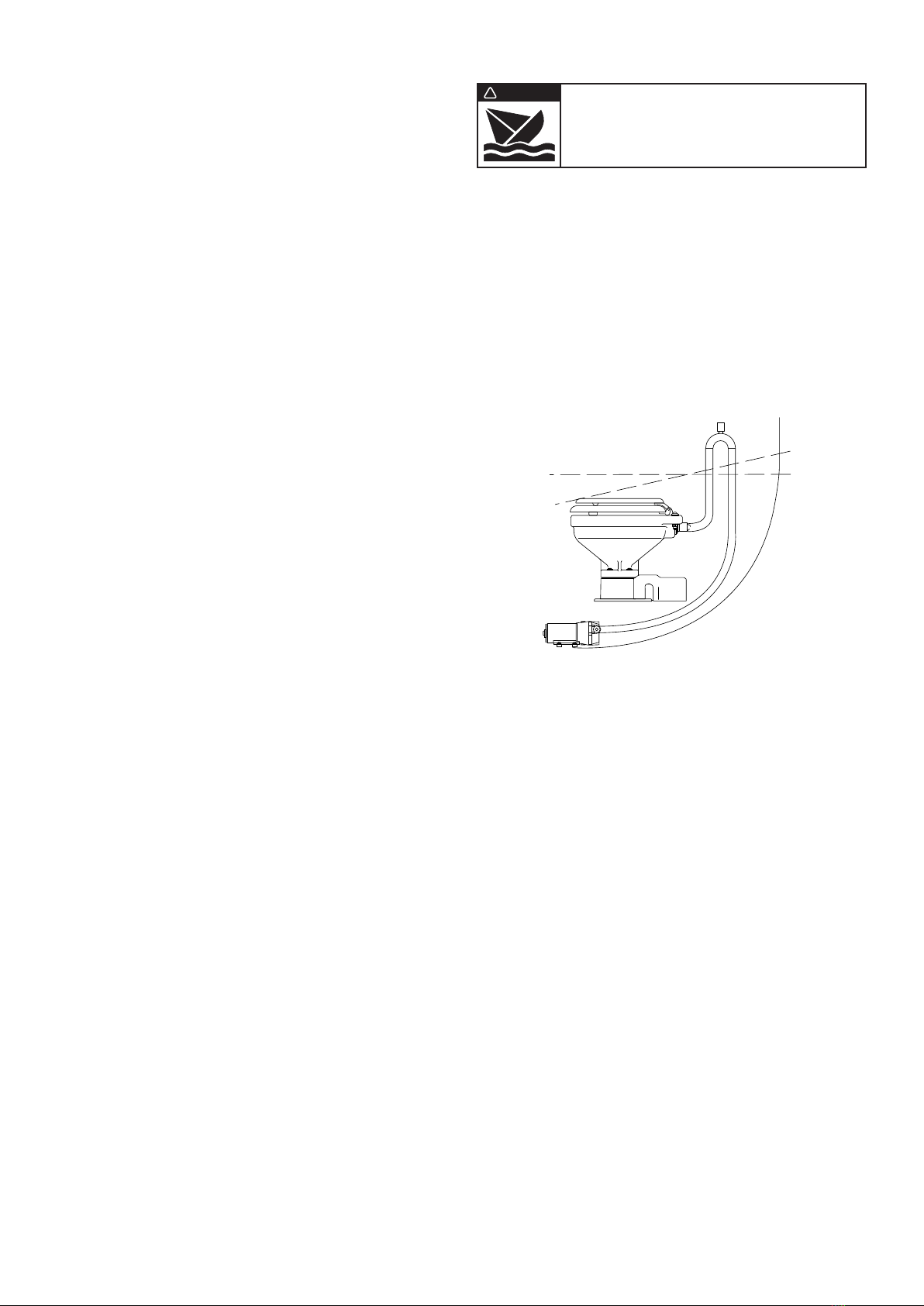
If the toilet is installed below the vessel’s waterline, in
order to prevent a siphon action from filling the toilet, a
properly positioned vented loop fitting must be installed
between the PAR-MAX pump and the back of the toilet
bowl. The vented loop fitting must be secured in a loca-
tion that remains at least 6-8 inches (15-20 cm) above
the waterline at all angles of heel and trim (see diagram).
The toilet discharge port is sized for 1" (25 mm) hose.
The discharge hose should be a quality grade reinforced
hose suitable for waste applications. Route the dis-
charge hose to the holding tank in the most direct way
with as few bends as possible. To retain some water in
the bowl, it is best to loop the discharge hose up about
8-10 inches (15-20 cm) as close to the toilet as practical
then on to the holding tank. It is best to avoid any dips or
low spots in the discharge plumbing that can act as
water traps and collect waste. If this occurs, waste can
solidify and cause a discharge blockage.
If the toilet is plumbed to an overboard discharge, and
is below the vessel’s waterline, the discharge plumbing
must include a properly positioned vented loop. The
vented loop fitting must be secured in a location that
remains at least 6-8 inches (15-20 cm) above the water-
line at all angles of heel and trim. The maximum dis-
charge head without a notable decrease in pump perfor-
mance is four feet (1.3 M).
ELECTRICAL
The electrical wiring should be independent of all other ac-
cessories. It should be made with marine grade copper
stranded wire of the gauge specified in the electrical spec-
ifications chart. Make all wire connections with mechanical
locking type connectors (crimp type butt connectors and
terminals). Ensure the circuit is protected by a proper sized
fuse or circuit breaker determined from the electrical spec-
ifications chart. Secure all wires to a solid surface approxi-
mately every eighteen inches (1/2 M) along their entire
length of run.
WARNING
! Flood hazard. Close inlet and outlet
seacocks prior to disassembling toilet.
Failure to do so can result in flooding
which can cause loss of property and life.
Waterline
Vented Loop
Heeled Waterline
Page 2


