Jade RJGR User manual

1
7355 E. SLAUSON AVENUE, COMMERCE, CALIFORNIA 90040 (323) 889-4888 Fax: (323) 889-4890
MADE IN USA
INSTALLATION INSTRUCTIONS
JADE GAS RANGE
MODEL RJGR
PLEASE READ THIS MANUAL COMPLETELY AND CAREFULLY BEFORE PROCEEDING.
IMPORTANT: Save these instructions for local inspector’s use.
IMPORTANT: Observe all governing codes and ordinances.
NOTE TO THE INSTALLER: Please leave this manual with the range for the consumer.
NOTE TO THE CONSUMER: Please retain this manual for future reference.
IMPORTANT
The installation of this range must conform with local codes or, in the absence of local
codes, with the National Fuel Gas Code ANSI Z223.1 - latest edition. If installed in
Canada, installation must conform with local codes, or with CAN/CGA B149.1, Natural
Gas Installation Code or CAN/CGA B149.2 Propane Gas Installation Code.
This appliance must be electrically grounded in accordance with local codes or, in the
absence of local codes, with the National Electrical Code, ANSI/NFA 70- latest edition.
In Canada, it must be electrically grounded in accordance with local codes or with CSA
C22.1 Canadian Electrical Code Part 1.
P/N 2400030000 06/03
WARNING: If the information in this manual is not followed
exactly, a fire or explosion may result causing property dam-
age, personal injury or death.
• Do not store or use gasoline or other flammable vapors
and liquids in the vicinity of this or any other appliance.
WHAT TO DO IF YOU SMELL GAS
•Do not try to light any appliance.
•Do not touch any electrical switch; do not use any phone
in the building.
•Immediately call your gas supplier from a neighbor’s
phone. Follow the gas supplier’s instructions.
•If you cannot reach your gas supplier, call the fire
department.
•Installation and service must be performed by a qualified
installer, service agency or the gas supplier.

2
IMPORTANT SAFETY INSTRUCTIONS
UNPACKING AND INSPECTION:
Do not use this range as a supplement to your furnace/
heater. It is not designed to heat up the kitchen nor
any other room. Using this appliance other than its
intended use could be dangerous.
Check that the container is upright. Check for visible
damages on the carton. If there is damage to the car-
ton, contact the carrier, and request an inspection. Do
not refuse shipment but file the appropriate freight
claims. Responsibility for shipping damage is with the
carrier and dealer or end user.
Cut the shipping straps and carefully lift the carton up
from the range. Check the range for visible damage.
If the range is to be installed on an area covered with
linoleum or any other floor covering, make sure that
the floor covering can withstand 90°F (65°C) above
room temperature without warping, shrinking or discol-
oring. Do not install the range over carpeting.
Remove, unwrap and temporarily lay aside any part or
accessory shipped with the unit and make sure that
there are no hardware or accessories left in the box for
accidental disposal. Make sure all packing material
and literature are removed from the oven before
connecting gas and electrical supply to the range.
CONTENTS PAGE
Important Safety Instructions............................................................... 1-2
Unpacking and Inspection................................................................... 2
Range Specifications........................................................................... 3
Legs Installation.................................................................................. 3
Casters Installation.............................................................................. 4
Curb Base Installation......................................................................... 5
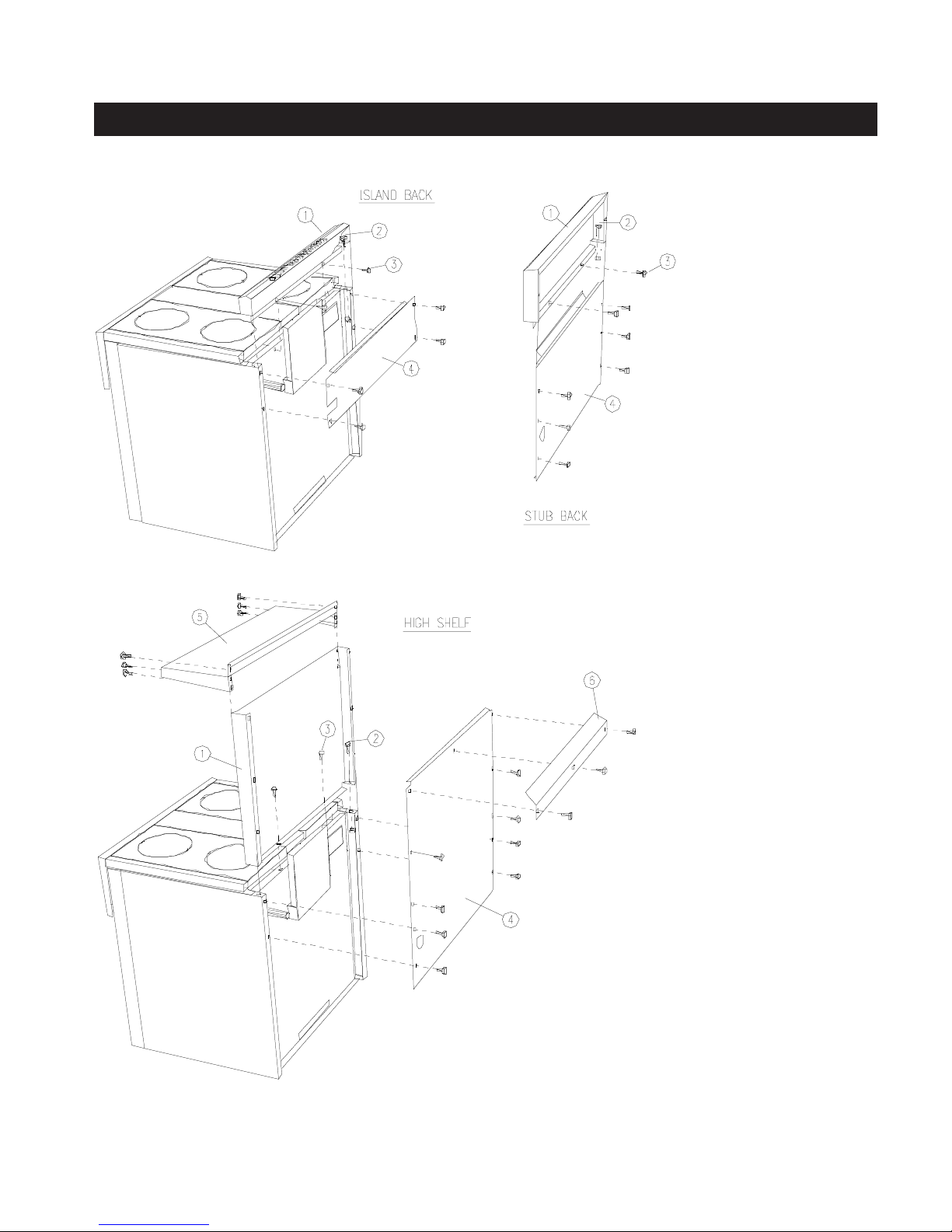
Stub Back Installation......................................................................... 6
Clearances Against Combustible Surfaces......................................... 7
Gas Connection.................................................................................. 8
Gas Conversion For RJGR Series .................................................. 9-10
Electrical Connection.......................................................................... 11
Initial Start-up and Burner Adjustment
Open top / Simmer ................................................................ 12
Infrared Broiler....................................................................... 13
Oven...................................................................................... 13
Wok........................................................................................ 14
Charbroiler.............................................................................. 14
Griddle.................................................................................... 14
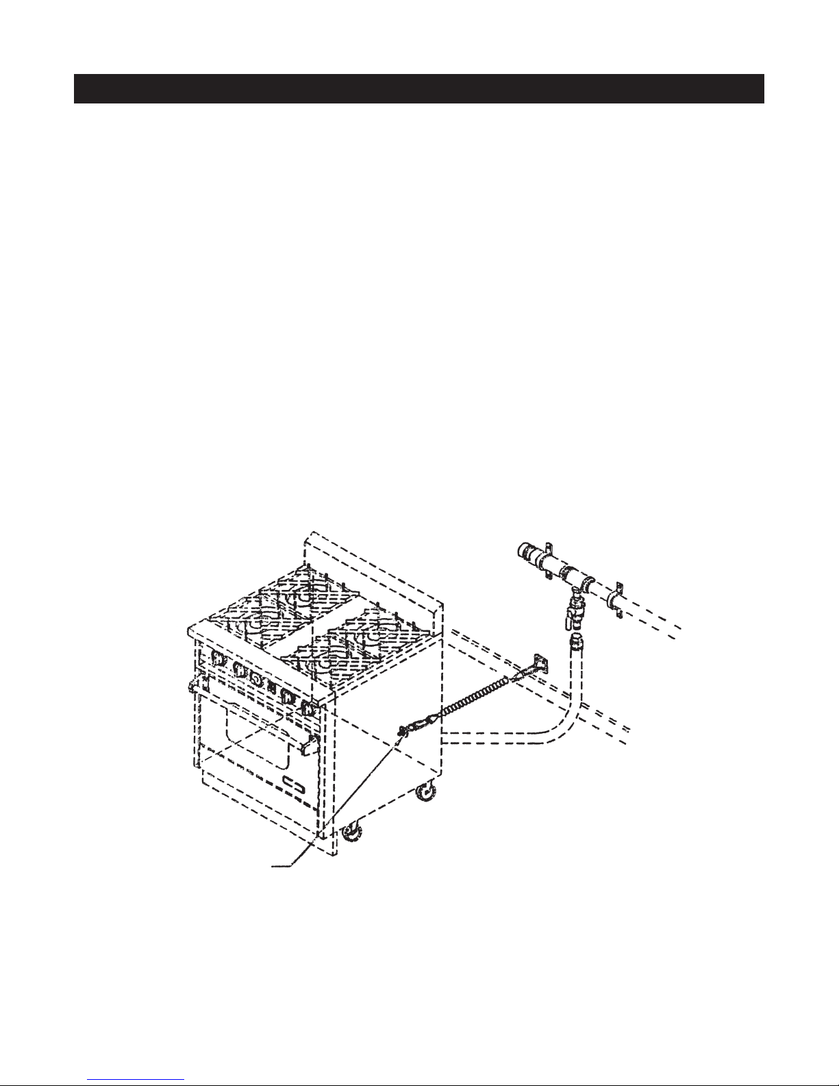
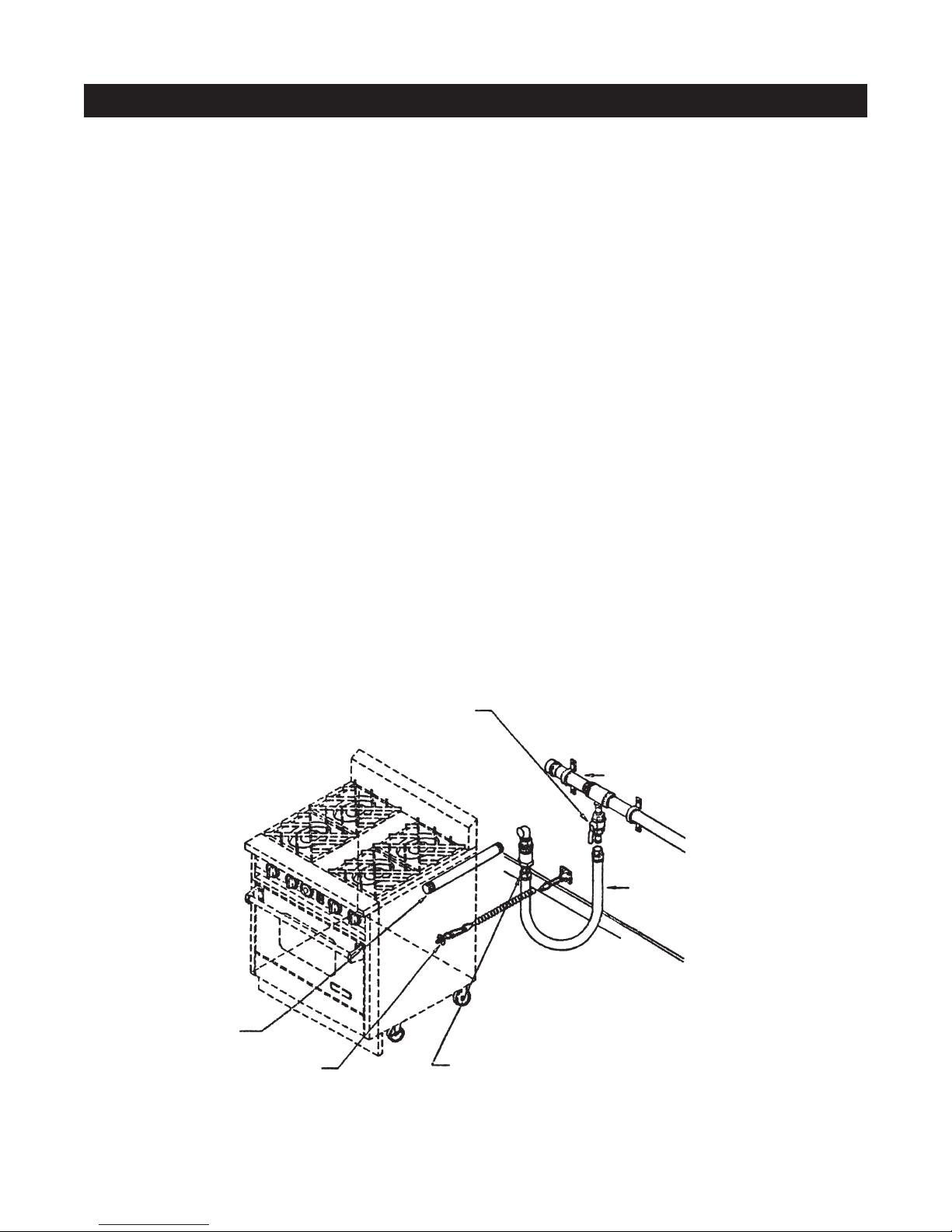
Installation of Anti-Tip Bracket............................................... 15-16

3
RANGE SPECIFICATIONS
The stainless steel legs are wrapped and packed sepa-
rately in the oven. The legs must be installed near
where the range is to be used to avoid pushing or slid-
ing the range that could cause damage to the legs and
to the floor covering. To install the legs it is strongly
recommended that a lift jack be used to lift the range
completely. Then screw the legs tightly to the bottom
of the range. The distance between the top of the range
(not including the cast iron grates) to the floor must be
at least 36 inches. The legs can be adjusted up to 2
inches higher by turning the stainless steel adjustable
feet using a 1” open end or adjustable wrench. Adjust
the legs so that the top of the range is even or higher
than the counter top.
IMPORTANT:
NEVER SET THE RANGE LOWER THAN THE
COUNTER TOP. THE HEAT FROM THE TOP BURN-
ERS CAN DAMAGE THE COUNTER TOP.
For proper baking results, it is important that the range
is leveled. To level the range:
1. Use a 1” open end or adjustable wrench. Turn the
adjustable feet equally until the top of the range is even
or higher than the counter top.
2. Install the oven racks.
3. Put a spirit level or a glass measuring cup partially
filled with water on one of the oven racks.
4. Adjust the legs’ feet using the wrench.
LEGS INSTALLATION
MODEL: RJGR - 30 MODEL: RJGR - 36 MODEL: RJGR - 48 MODEL: RJGR - 60
TYPICAL FOR ALL MODELS

4
CASTERS INSTALLATION:
IMPORTANT: The top of the range must be even or
higher than the counter top. The heat from the top burn-
ers can damage the counter top.
When the appliance is installed with casters, it must be
installed with the casters supplied, a connector com-
plying with ANSI Z21.69 and a quick disconnect de-
vice complying with ANSI Z21.41. It must also be in-
stalled with restraining means to guard against trans-
mission of strain to the connector.
Below is a typical restraining device.
Casters are used for easy access in servicing or clean-
ing the appliance. However, unlike the legs, casters
are not adjustable. Any adjustment needed for level-
ing the range is accomplished by placing shims on the
floor. When checking to see if the range is level, al-
ways use a spirit level or glass measuring cup placed
on one of the racks. It is extremely important for proper
baking results that the racks are leveled.
When installing casters, it is strongly recommended
that a lift jack be used to lift the range completely.
Install the two casters without brakes to the rear. In-
stall the two casters with brakes to the front for acces-
sibility.
After the range is set and leveled on its final location,
set the caster brakes on to prevent movement of the
range under normal use.

5
CURB BASE INSTALLATION
The curb base must be installed after the range has
been leveled and set properly in its final location.
To install the curb base, simply remove the kick plate
(the panel immediately below the oven door) and lo-
cate the mounting holes at the front of the range base.
Secure the curb base to the front of the range base
using the two hexagonal sheet metals screws provided
with the curb base. If the legs are adjusted to the
minimum height of 4 inches, the curb base can have
0 to 1/8 gap between the floor. When the legs are
adjusted higher, the gap can be as high as 2 inches
which may not be visually objectionable and not need
a filler. If a filler is desired, build a filler attached to the
floor or to the adjacent cabinets using screws or other
removable fasteners, so that the range can be readily
removed if necessary.

6
ISLAND BACK/STUB BACK/HIGH SHELF INSTALLATION:
TO INSTALL ISLAND BACK:
1 INSTALL FRONT.
2 SECURE THE SIDE FLANGES OF
THE FRONT USING BOLT, AND
NUT ON EACH END.
3 SECURE THE BOTTOM LIP OF
THE FRONT AGAINST THE BACK
OF THE RANGE USING 2
SCREWS (4 SCREWS ON
DOUBLE OVENS).
4 INSTALL BACK BOTTOM WITH
THE SLOT MATCHING THE GAS
SUPPLY PIPE AS SHOWN.
SECURE BOTTOM USING 4
SCREWS.
TO INSTALL STUB BACK:
USE SAME PROCEDURE AS
ISLAND BACK.
TO INSTALL HIGH SHELF:
1 INSTALL HIGH SHELF FRONT.
2 SECURE THE SIDE FLANGES
OF THE FRONT USING BOLT,
AND NUT ON EACH END.
3 SECURE THE BOTTOM LIP OF
THE FRONT AGAINST THE BACK
OF THE RANGE USING 2
SCREWS (4 SCREWS ON
DOUBLE OVENS).
4 INSTALL BACK WITH THE HOLE
MATCHING THE GAS SUPPLY
PIPE AS SHOWN. SECURE BACK
USING 8 SCREWS.
5 HOOK HIGH SHELF TO TOP OF
FRONT, AND SECURE SHELF
WITH 6 SCREWS.
6 INSTALL DEFLECTOR AND
SECURE IT WITH 3 SCREWS.

7
CLEARANCE AGAINST COMBUSTIBLE SURFACES:
The Jade Gas Range must be installed in accordance
with the minimum clearances as illustrated below.
Avoid placing cabinets directly above the range in
order to reduce the hazards in reaching over the
range. When installed, the maximum depth of the
overhead cabinets is 13 inches.
A required distance of 40" minimum vertical clear-
ance between the cooking surface and combustible
construction above the appliance should be main-
tained. We recommend 30" distance from the bot-
tom of a standard ventilating hood made of sheet
metal or noncombustible material to the range top
surface. Because of the high heat output of the Jade
RJGR Gas Ranges, a suitable exhaust hood must
be installed above the range. Because the design
and efficiencies of the ventilating hoods vary from
one manufacturer to another, consult your hood sup-
plier or manufacturer for their recommended hood
size, the hood distance from the range top, and re-
quired CFM's. The hood width must be at least the
same width as the range. The hood depth must be
19" minimum.

8
GAS CONNECTION:
IMPORTANT
Shut off gas supply before removing an existing range
and leave it off until new installation is completed.
Use only pipe joint compound that is approved for use
with petroleum gases. Install a manual shut-off valve
in an accessible location in the gas piping, external to
the range for the purpose of turning on or shutting off
gas to the range. To facilitate in moving or servicing
the range, a flexible connector complying with
ANSIZ21.69 is recommended.
Check for gas leaks using soap-water solution. Do not use open flame to check for leaks.
•The appliance must be isolated from the gas sup-
ply piping system by closing its individual manual
shut off valve during any pressure testing of the
gas supply piping system at test pressures equal
to or less than 1/2 psig (3.5 kPa). Check incoming
gas supply pressure and the manifold pressure
(after the regulator) using a manometer. The re-
quired manifold pressure for natural gas is 5" wa-
ter column and for LP is 10" W.C. The gas supply
line must be at least 1" W.C. above the manifold
pressure and must not exceed 14" W.C. (3.5 kPa or
1/2 psig)
Installation of this range must conform with local codes.
Call the local gas supplier for the applicable codes in
the area. If there are no codes, the installation must
conform with the NATIONAL FUEL GAS CODE ANSI
Z223.1 - Latest Edition. A copy of this code may be
obtained by contacting:
CSAAmerica
8501 E. Pleasant Valley Rd.
Cleveland, Ohio 44131
(216) 524-4990
www.csa-america.org
The maximum allowable incoming gas pressure for
the regulator installed in the range is 1/2 psig (pounds
per square inch gauge), equivalent to 14 inches water
column. For LP-installation, a step down regulator must
be used to bring down the gas pressure from the LP
bottle to below 14 inches. The minimum incoming gas
pressure to the regulator must be 1 inch above the
range designed manifold pressure. Refer to chart on
gas conversion for the gas pressures.
1/2" PIPE NIPPLE
RESTRAINING DEVICE QUICK DISCONNECT
FLEXIBLE HOSE
GAS SUPPLY
GAS SHUT-OFF VALVE

GAS CONVERSION FOR RJGR SERIES
All Jade cooking appliances are designed and engineered to operate efficiently and safely with either natural or propane gas. However,
each gas requires its own specific regulator and gas orifice setting. The name plate on your unit identifies its original gas setting. This conversion must
be done by an approved service agent.
WARNING: TURN OFF GAS AND ELECTRICAL SUPPLY BEFORE
ANY PROCEDURE BELOW IS PERFORMED.
A) REGULATOR CONVERSION PROCEDURE (See Figure A)
The regulator can be converted by turning the regulator cap over. The marking on the cap for the
type of gas setting will be exposed.
B) ORIFICE CONVERSION PROCEDURE (See Figure B)
1) Remove the orifice hood from the valve or bi-metal valve. Extreme care should be taken to avoid damage to threads on the
orifice and/or valve.
2) Make sure that all internal surfaces of the new orifice and valve are clean.
3) Make sure that dirt, dust, and other contaminants are not allowed to get inside the valve or orifice hood during assembly.
4) Install new orifice hood by carefully screwing it onto the valve or bi-metal valve. Follow proper orifice sizes indicated on chart
below.
5) Adjust air shutters for optimum burner performance.
WARNING: IN ORDER TO AVOID A FIRE OR AN EXPLOSION CAUSING PROPERTY DAMAGE,
PERSONAL INJURY, OR DEATH, EXTRA-PRECAUTION SHOULD BE TAKEN
WHEN CONVERTING FROM NATURAL GAS TO LP-PROPANE BY FOLLOWING
CORRECT ORIFICE SIZES AS SPECIFIED ON CHART BELOW.
WARNING: ALL ORIFICES WITH NO EXCEPTION MUST BE CONVERTED.
Before turning the gas supply on, check for leaks and make sure that all control knobs are turned OFF.
MAXIMUM incoming pressure to the regulator : 14” WATER COLUMN
MINIMUM incoming pressure to the regulator : 6” W.C. — NATURAL GAS
11” W.C. — LP-PROPANE
MANIFOLD PRESSURE (outgoing pressure from regulator) : 5” W.C. — NATURAL GAS
10” W.C. — LP-PROPANE
ORIFICE SIZES*
BTU/HR NATURAL GAS LP-PROPANE
SIMMER BURNER 10,000 #54 DMS #63 DMS
OPEN BURNERS 15,000 #50 DMS #57 DMS
INFRARED BROILER 15,000 #51 DMS #57 DMS
WOK 20,000 #45 DMS #56 DMS
GRIDDLE 15,000 #51 DMS #57 DMS
CHAR BROILER (2) 12,000 #52 DMS #58 DMS
14” OVEN 20,000 #45 DMS #55 DMS
25” OVEN 27,500 #41 DMS #53 DMS
31” OVEN (2) 20,000 #45 DMS #55 DMS
*For elevations at or above 2,000 feet consult with factory. 9

10
GAS CONVERSION FOR RJGR SERIES
FIGURE B
TO FRONT OF
OVEN SHUT OFF VALVE RANGE
LIFT UP AS SHOWN
FOR OPEN POSITION
REGULATOR CAP
CLOSED END EXPOSED
IS SET FOR NATURAL GAS
GAS INLET
REGULATOR CAP
OPEN END EXPOSED
IS SET FOR LP-PROPANE
FIGURE A

11
ELECTRICAL CONNECTION
RJGR models require a 120 volt, 60 hertz, 15 AMP,
AC properly grounded household circuit. The circuit
must be protected with a circuit breaker or time delay
fuse.
Improper grounding can affect the spark ignition sys-
tem. If a grounded three hole outlet is not available,
have an electrician change the old outlet or install a
new one. To temporarily use a polarized and grounded
two hole outlet until a grounded three hole outlet can
be installed, a grounded three hole adapter plug can
be used. Have an electrician test the outlet for proper
grounding.
Before plugging in the range, make sure all the con-
trols, burner knobs and power switch, are in the OFF
position. To turn power switch to OFF, depress the
rocker switch, opposite to the power indicator light.
This appliance is equipped with a three prong (ground-
ing) plug for your protection against shock hazard and
should be plugged directly into a properly grounded
three prong receptacle. Do not cut or remove the
grounding prong from this plug. This appliance must
be electrically grounded in accordance with local
codes or, in the absence of local codes with the Na-
tional Electrical Code ANSI/NFA 70-latest edition. In
Canada, it must be in accordance with CSAC22.1
Canadian Electrical Code Part 1. A copy of the Na-
tional Electrical Code can be obtained by writing to :
National Fire Protection Association
Batterymarch Park
Quincy, MA 02269
SPARK
MODULES
IGNITOR
OPEN TOPS AND
CHARBROILERS
OVEN LAMP
FAN SWITCH
POWER
SWITCH
GRIDDLE
THERMOSTAT
GRIDDLE LIGHT
VALVE SWITCHES
GRIDDLEOVEN
BAKE LIGHT
FAN MOTOR
IGNITOR
IGNITOR
BI-METAL
VALVE
BI-METAL
VALVE
BI-METAL
VALVE
BROIL LIGHT
OVEN LAMP
BK
BR
OVEN
THERMOSTAT

12
INITIAL STARTUP AND ADJUSTMENT
The air for combustion is supplied through the front of
the range. The combustion air is exhausted upward
and through the flue way. Do not obstruct the flow of
combustion and ventilation air.
IMPORTANT
For proper operation of the range, it is very impor-
tant that the unit is leveled. To level the range:
1. Use 1” open end adjustable wrench. Turn the
adjustable feet equally until the top of the range is
even or higher than the counter top.
2. Install the oven racks.
3. Put a carpenter’s spirit level or a measuring cup
partially filled with water on one of the oven racks.
4. Adjust the leg’s feet using the wrench.
Before startup, make sure that the range has been
carefully checked for gas leaks and that the range has
been properly connected to electric power.
Every RJGR Range is fully tested and adjusted in
the factory. Due to the difference in gas heating
values, elevations, and ventilating conditions of
every installation, minor adjustment of the burners
may be necessary. Carefully follow the procedures
described below.
OPEN TOP / SIMMER
Open top burners are in sets of two. The right burner
knob controls the front burner and the left knob con-
trols the rear. These top burners are rated at
15,000 BTUs per hour. They can be turned down to
1,000 BTUs for delicate cooking. For simmering, a
dedicated simmer burner is located at the right rear.
This smaller burner has a maximum rate of 10,000
BTU/HR and can be turned down to 500 BTU/hr.
To ignite the burners, push the corresponding knob
in, turn knob to HI and then to LITE position. You will
hear a clicking sound indicating the proper operation of
the spark igniters. After the air in the supply line has
been purged, the burner should ignite within a few sec-
onds. After ignition, turn knob to desired setting. The
clicking sound should stop. Please remember... these
burners produce a lot of heat (15,000 BTU/hr.) at HI
setting. Do not operate the burners for an extended
period of time without cookware on the grates. The
porcelain on the GEOGRATES may chip without the
cookware to absorb the heat. Also because of the
high input rate, a slight popping sound is normal during
ignition of the burners.
The burners are tested and adjusted at the factory.
The burner flames when set on HI must have clean,
sharp blue flames with distinct inner cones of about 1
inch high.

13
If the flames are yellow, soft, lazy with indistinct cones,
it signifies insufficient air. For natural gas it is normal
that the burners have blue flames with little orange
tips. For propane, it is normal to have blue flames with
yellow tipping. If the flames are noisy and tend to lift
away from the burner, then it means excessive air. To
adjust the air, loosen the Phillips screw on top of the air
shutter and turn air shutter to correct setting. Tighten
the screw after adjustment. It is normal that the smaller
burner has sharper flames than the large burners.
Turn the burner knob to LOW (simmer) setting. At
this setting, the burner ports must be fully lit with the
smallest possible flames without flickering. If some
ports do not stay lit or if the flames are high, adjust-
ment is necessary. To adjust, set knob to low and pull
out the control knob. With a skinny flat screw driver
(1/8" wide) locate the adjusting screw at the center of
the valve stem. Turn the screw clockwise to lower the
flame and counter clockwise to increase.
OVEN
red color to emit infrared heat. There is no adjustment
to the infrared burner.
NOTE: The noise of gas flowing into the infrared
burner is normal.
The ceramic burner surface will glow into an orange
INFRARED BROILER
The oven burner and igniter are accessible by remov-
ing the oven bottom pan. The oven uses a glowbar
ignition system. To light oven turn power switch on.
Push and turn oven thermostat to desired setting. The
orange indicator “BAKE” light will come on. The glowbar
igniter will glow and after a few seconds the oven burner
will ignite. The burner flames should be blue with dis-
tinct cones 1 to 1 1/4 inches high. If the flames are yel-
low, soft, lazy with indistinct cones, it signifies insuffi-
cient air. For natural gas, it is normal that the burners
have blue flames with little orange tips. For propane, it
is normal to have flames with yellow tipping. If the flames
are noisy and tend to lift away from the burner then it
means excessive air. To adjust burner flames, loosen
the air shutter screw and turn air shutter. Retighten the
air shutter.
NOTE: The noise of gas flowing into the burner is nor-
mal.
The infrared broiler uses a glowbar ignition system. To
light the broiler, turn power switch on, push and turn
oven thermostat to broil. The red indicator “BROIL”
light will come on. The glowbar igniter will glow and
after a few seconds the infrared burner will ignite.

14
Ignition and adjustment procedures for
the wok burners are the same as the
open top burners.
WOK BURNERS
CHARBROILER
½
”
Similar to the open top burners, the
charbroiler uses spark ignition. To light
burner, push knob in, turn knob to HI and
then turn to LITE. To adjust burner flames,
turn air shutters. The burner flames should
be blue with 1/2" high distinct cones. It is
normal that during initial startup and when
the knob is set on HI, the first inch of the
ports are not lit.
After the burners have established and
warmed-up, the front ports will stay lit.
GRIDDLE
½” To ¾
”
The griddle uses a glowbar ignition
system. To light the griddle burner, turn
power switch on. Push and turn griddle
thermostat to desired setting. The
glowbar igniter will glow and in 20
seconds the griddle burner will ignite.
The burner flames should be blue with
distinct cones 1/2" to 3/4" high. To
adjust burner flames, loosen air shutter
screw and turn air shutter.


Other manuals for RJGR
1
Table of contents
Other Jade Cooktop manuals
Popular Cooktop manuals by other brands

Frigidaire
Frigidaire GLCS389FSA Wiring diagram

Samsung
Samsung GN642HFGD Installation and user manual

Awanti
Awanti BCT115J1B-IS instruction manual

Electrolux
Electrolux EW36CC55GW - 36in Electric Cooktop Specifications

Smalvic
Smalvic BIS 950 RT Use and maintenance instructions

Whirlpool
Whirlpool GJC3055RB00 parts list