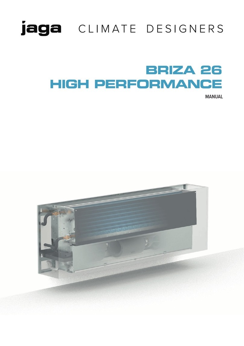
Jaga OXYGEN User manual

Oxygen Technical Manual
Oxygen Description
Intelligent, healthy energy-efficient IAQ control
Jaga Oxygen is an energy-efficient, intelligent and fully programmable heating and ventilation solution
which creates a fresh, healthy and comfortable indoor climate in buildings of any age or type.
Particularly suited for rooms with high occupancy such as classrooms, offices and care homes, Oxygen
delivers clean, healthy, fresh air on demand and in a highly energy efficient way.
In schools, poor indoor air quality (IAQ) has long been an issue and has been proven to have a detrimental
effect on educational performance. Similarly in an office environment, good indoor climate is essential for
productivity and to reduce sickness and absenteeism. In care homes the need is even more acute as
poor IAQ, due to excess CO2, is a real threat to healthy living and occupants’ comfort.
How Does it Work?
The Oxygen system works by monitoring and measuring the air quality in a room and cutting in
automatically when required. This ensures that an adequate supply of fresh, clean outside air is
introduced into the room and the contaminated, stale air is removed.
As the Oxygen’s intelligent demand controlled (heating and) ventilation system only vents fresh air when
required it is more efficient than natural ventilation and eliminates the drawbacks of draughts, stuffiness
and security risks. During the hot summer months Oxygen’s boost function can be used to deliver effective
secure night-time air purging. This cools the building fabric down so that the environment is more
comfortable first thing in the morning.
The Oxygen system can be specified with a wide range of Jaga wall-mounted heating solutions. Oxygen
systems can be linked to an existing building management system, centrally controlled in a stand-alone
system, or even controlled simply through a panel on the radiator.
The system features Oxygen Refresh fans built into Jaga’s patented Low H2O radiators. The refresh unit
draws in outside air and filters it before discharging it through the radiator and into the space.
The Jaga Master controller regulates and balances inlet (and exhaust if installed) air. The exhaust unit
directs stale air outside or into central corridors to provide a degree of heat recovery. The Oxygen CO2
sensor controls the whole system, continuously measuring the air quality and reacting accordingly by
replacing stale air with fresh clean air. As the ventilation demand changes the Low H2O radiator is able
to respond instantly offering excellent fast response heating control.
The fresh air, depending on the requirements of the CO2 sensor, will vary from 30 m3/hr on 1.0 vdc output
from main oxygen control panel to 200 m3/hr on 4.5 vdc output from main oxygen control panel, which
will be boosted up to 400 m3/hr on 7.0 vdc output once the ‘BOOST’ button has been depressed on the
smart switch.
When using The Jaga Oxygen control system, remote access can provide real-time monitoring of room
conditions including, CO2, temperature and air volumes.
Also, with the ‘Cloud Service’ the current status can be monitored and changed remotely – ideal for
Facility Managers.

Oxygen Technical Manual
Installed Components
CO2 Sensor
CO2 Sensor communicates with the other control components over the Jaga bus system to control
and balance the inlet and exhaust fans.
This sensor also measures the room temperature and can control the heating valves and ventilation
speed to provide a degree of temperature control within the space.
Refresh Unit & Damper
The Oxygen air inlet fans are housed within the Jaga Low H2O radiator casing. Depending on the
type of casing being used, up to four air inlet fans can be fitted into one radiator, therefore saving
valuable wall space.
Each of the air inlet fans require a 163mm diameter feed to outside air and accommodate the damper
assembly. The damper closes when the fan is not operational to ensure full control.
Exhaust Fan
An exhaust fan is used to remove stale air from the space. It can accept a 0 – 10 volt signal. The
fan curve is programmed into the Jaga Master Controller to ensure accurate control, balanced with
the inlet air from the refresh units.

Oxygen Technical Manual
Room Smart Switch
A single 2-button switch can be installed in each room to provide a user interface with the system.
The indicator lights illuminate in different colours depending on the mode of operation.
Central Control Panel and Associated Components
The panel is located in a central location(comms room or plant room) and houses the master control
unit to communicate with all bus components.
The front of the panel has an isolator and smart switch for service and maintenance purposes.
Analogue Output Module 0..10vdc
Each refresh unit (maximum four refresh units) and exhaust fan/s, require an analogue output
module to convert the Green Wire BUS signal into a 0-10vdc control signal from the controller using
an inbuilt program by Jaga to configure their speed of running on the dictates of the CO2 sensor.

Oxygen Technical Manual
Display
A display is provided to give an indication to of the system conditions including settings, operating
speeds and CO2 levels.
Radiators and TRVs
The radiator design is to suit the requirements of the specification, and houses a low water content
heat emitter and valves.
The radiators are fitted with TRVs to control the water flow based on the space temperature. This
can be traditional manual type or electrically activated.

Oxygen Technical Manual
Refresh Unit Description
Type Of Units Available with Oxygen
Model
LowH2O
Standard
H min.
Low H2O
Twin
H min.
Length minimum
1 Unit 2 Units 3 Units 4 Units
Strada 500 650 800 1400 2400 2800
Maxi WT/WF N/A 740 1033 1433 2033 N/A
Maxi FT/FF N/A 740 1033 1433 2033 N/A
Guardian FT N/A 800 840 1440 N/A N/A
Guardian WT N/A 600 840 1440 N/A N/A
Tempo 500 600 800 1400 2400 2800
Play 650 650 1000 N/A N/A N/A

Oxygen Technical Manual
Performance Data
This shows the performance data, in graph form, of the Oxygen Refresh Unit showing Airflow (m3/hr)
and Noise Level (dBA) against Control Voltage (vdc).
All the tests have been taken on the Refresh Unit alone, without radiator casing.
0
10
20
30
40
50
60
70
80
0
50
100
150
200
250
300
350
400
450
0.0 1.0 2.0 3.0 4.0 5.0 6.0 7.0 8.0 9.0 10.0
NOISE LEVEL - DBA
AIR FLOW - M3/HR
CONTROL VOLTAGE
Voltage vs Airflow
Airflow m3/hr Noise LwA SRL Apr 2016

Oxygen Technical Manual
Fitting Instructions
Fit the element and brackets as their fitting instructions, then mount the template:
Mounting
template
REFRESH UNIT
OXRU.015
REFRESH UNIT
OXRU.015

Oxygen Technical Manual
Core drill through the wall from the marked out circle from the mounting template :
Wire the refresh unit as described in the wiring section.
Wiring of System

Oxygen Technical Manual
Typical Oxygen system layout –

Oxygen Technical Manual
Refresh Unit wiring -
Exhaust Fan –
Internal circuit board of Exhaust
Fan

Oxygen Technical Manual
Green Wire BUS Installation –
Example of OXJC.03E
Product Description –
The aim of the data BUS is to link the controller with all the Jaga input and output modules. The power
supply and control signals are sent from the controller via 2-wire data BUS to the various connected
consumers/users(switches, output modules, displays etc).
The OXJC01 and OXJC01E have 1 BUS output, OXJC02 and OXJC02E have 2 BUS outputs, OXJC03 and
OXJC03E have 3 BUS outputs.
Maximum BUS load –
The BUS on all of the controllers can supply a maximum of 500mA. When calculating the load on each
BUS the power consumption per module must be taken into account :
CO2 Sensor - 50mA
Master controller - 60mA
Output module - 15mA
Smart switch - 10mA
Relay Module - 20mA

Oxygen Technical Manual
Mounting Variations –
The BUS can be mounted in any architecture(closed loop, tree, star) as long as the distance and section
requirements are respected.
BUS cable –
It is recommended to use the QBUS cable or any other cable with minimum 2 x 1mm2 conductors as a BUS
lead.
BUS Lengths –
The BUS can be installed up to a length of 200 metres. The maximum distance between the OXJC and the
module that is farthest away from the OXJC may be 200 metres.
We strongly recommend to run the BUS in a loop and join it at the controller. In this case (with a sealed loop)
we can increase the total length to 400 metres. The BUS connection will continue working, even when the
circuit is interrupted, the it would work as a star.
Features of the BUS –
The BUS consists of 2 conductors (minimum 2 x 1mm2)
The BUS has no polarity
The response time for 1 output is 20 msecs and 0.1 secs for 388 outputs.
The BUS operates in 2 directions (bi-directional) and each module can send and receive.
The BUS allows for simultaneous communication (programming and operations can be carried out
at the same time)
There are no BUS conflicts or waiting times when several operations are carried out simultaneously.
The BUS supplies power to and controls all modules via the controller.

Oxygen Technical Manual
Maintenance
Every 6 months
Clean filters in refresh units
Clean external grilles to remove blockages
Every 12 months
Replace filters in refresh units
Check all electrical connections are tight
Clean heating element
Service central heating system as recommended by boiler manufacturer and heating system
installer. This would typically include, but not limited to:
o Check operation of all safety valves
o Check system pressures
o Check cleanliness of system fluid
o Check operation of all heating components
Control System
The control system is a fully programmed control system and is maintenance free. Should this
system need to be changed as a result of damage or failure, please contact Jaga Heating Products
(UK) Ltd. See final page for contact details.
Refresh Units
The refresh unit is located inside the radiator casing, and houses the filter element. This will need
to be removed and cleaned / replaced. The filter element is in the bottom section of the refresh unit
and can be removed by sliding it out.
Radiator
The removal of the radiator casing can be found in its own fitting instructions by following in reverse
order.
The casing is manufactured from painted steel and may be cleaned with any normal detergent. Do
not use dry cleaning fluid or any other product containing volatile solvents.
The heating element is manufactured from copper tube, brass collectors with coated aluminium
convector fins. During operation the convector heating element filters dust and coarse particles from
the air. It is important for the efficiency of the convector that the airways are kept clear at all times if
possible. It is advisable to check during routine maintenance that nothing is blocking or obstructing
the top fins (for example; paper, food or other foreign bodies). Also check that there is no build-up of
dust on the underside of the element.
Easy access with a vacuum cleaner to the underside of the convector is possible.

Oxygen Technical Manual
Contact Details
Jaga Heating Products (UK) Ltd
Jaga House
Orchard Business Park
Bromyard Road
Ledbury
HR8 1LG
Tel: 01531 631 533
Fax: 01531 631 534
Web: www.jagaoxygen.co.uk
Table of contents
Other Jaga Fan manuals
Popular Fan manuals by other brands

EUROM
EUROM VT9-blanc Instruction leaflet

Vornado
Vornado 723DC owner's guide

Field Controls
Field Controls FIELD DIRECT VENT SYSTEM FDVS product manual

Monte Carlo Fan Company
Monte Carlo Fan Company 5DIC52 D Series Owner's guide and installation manual

emerio
emerio TFN-212915.10 instruction manual

Atlas fan company
Atlas fan company Acqua instruction manual