Jakson & Company JakPower Kirloskar Koel Green EA10 G1 Instruction Manual


We can achieve excellent performance from a Silent DG set,
if proper care is taken during its installation. (The following
suggestions shall help you to achieve optimum performance
from the D.G. Set.)
For Assistance
Please contact our customer care at C-266-267, Mayapuri Industrial Area, Phase-II,
New Delhi-110 064
Mobile No. 9871590738, 9871590740
Phone No. 011-28114072 (D), 28111510, 28113231, Fax No. 28113149
e-mail: [email protected], [email protected]
In case you are not satisfied, kindly register your complaint to
Jakson care No. - 8800447864
General Note:
1. Please always sign the report made by our Service Engineer.
2. Warranty is applicable for two years for engine & alternator only
subject to use of Kirloskar K-Oil Premium, Kirloskar genuine filters,
K cool super plus and services sourced through KOEL authorized
Service Dealer.
Revalidation :- If Generator set kept without commissioning (not in F
operation after delivery) for 6 months or more without preservation
then Engine revalidation must be carried out through Authroized
Kirloskar Dealer and Customer has to bear revalidation cost.
Disobedience of above instruction may lead to problem in
entertaining claim.
JAKSON & CO.
P
O
W
E
R
BY
KIRLOSKAR
880 633 4433
JAKSON & COMPANY
P
O
W
E
R

S. NO. DESCRIPTION PAGE NO.
1. SELECTION OF SITE 1
2. FOUNDATION DETAILS & 2-3
GUIDELINES
Ref. Drawing For Foundation of Gen Set
3. EARTHING SYSTEM 4
4. EXHAUST PIPING 5
5. FUEL PIPING 6
6. CABLING 7
7. BATTERY CHARGING PROCEDURE 8
8. SUMP CAPACITY 9
9. CHECK UP BEFORE STARTING 10
THE DG SET.
10 SUMP CAPACITY (NEPAL) 11
11 ROUTINE MAINTAINANCE OF SDG SET 12
12. PRE-COMMISSIONING CHECK 13
13. ROUTINE CHECK POINTS 14
14. DO'S & DON'T'S 15
15. TROUBLE SHOOTING - ENGINE 16-20
16. TROUBLE SHOOTING - ALTERNATOR 21-22
TROUBLE SHOOTING GUIDE FOR 23
MANUAL PANEL
TROUBLE SHOOTING GUIDE FOR 24-25
AMF PANEL
INDEX
JAKSON & CO.
17.
18.
19. SAMPLE WARRANTY CERTIFICATE (NEPAL) 26
20 SAMPLE WARRANTY CERTIFICATE (DOMESTIC) 27
21. REVALIDATION POLICY GENSET 28-29
22 WARRANTY TERMS AND CONDITION 30
FOR BATTERY

SELECTION OF SITE
ØProper space should be there for placement and opening of doors of the
Silent DG set.
ØThere should be atleast 1.5 meter free space around the DG set for
proper operation and maintenance.
ØThere should be cross ventilation of air to ensure proper cooling of DG
set. Exhaust gases and hot air discharge should not re-circulate inside
the acoustic enclosure (canopy).
Ø If Genset is to be installed in the room, please ensure proper cross
ventilation and surrounding space.
ØThere should be no restriction for fresh air suction and hot air discharge.
If 2 nos. DG sets are installed at the site, ensure that hot air outlet of the
one DG set does not become the fresh air intake of the 2nd DG set.
Ø If Genset is to be installed in the basement, please ensure ventilation
with respect to Air requirement and clear space for every maintenance.
ØDistance between two SDG set should be minimum 1.5 meters.
ØA low height shelter for the Silent DG Set should be avoided. It should
not obstruct the hot air outlet, shelter height minimum 1.5 meter or
equal to height of genset
ØIt is preferable to install the DG set in an open area. No shade (roof) is
required over it. However, if the AMF Panel is outside the Acoustic
Enclosure, then a shelter is recommended for the AMF Panel.
ØFor Roof Top Installation, ensure that the civil structure is capable to
bear the static and dynamic load of DG set. The load of the Silent DG set
should be borne by Columns and Beams of the building.
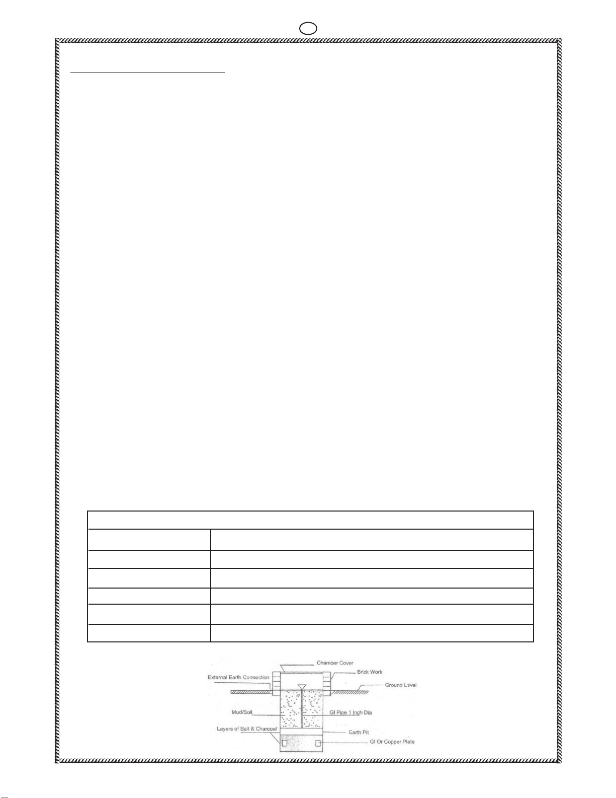
ØProper space should be there for Earthing.
ØIf there are no space constraints, the DG set should be placed near the
distribution panel.
ØThe DG set should be located away from polluted surroundings such as
corrosive fumes, cement dust, fibres, cotton and toxic chemicals to
avoid overheating of the D.G. Set.
Ø There should be sufficient space around the Genset to avoid resonance
and echo effect which contributes to abnormal sound from Genset.
Ø The space should be open without any obstacles.
1
JAKSON & CO.

FOUNDATION DETAILS AND GUIDELINES
A. Ground base Foundation (RCC/PCC)
ØThe foundation should be water leveled and at least 300mm above the
ground level to maintain cleanliness and avoid flooding.
ØThe length and width of the foundation should be at least 600mm to
800 mm more than that of the DG set size i.e. 300mm on each side.
Check the foundation level diagonally as well as across the length and
width.
ØPlease refer to the foundation drawing attached herewith (page-3).
ØA rigid foundation ensures the least vibration. Sand Filling should be
there around the foundation. 18mm rubber matting must be used over
the foundation to minimize the vibration effect and noise leakage.
ØEnsure that the foundation to support 1.5times of the total wet weight
of the single generator and 2 times of the total weight for the multiple
generators.
ØPlease refer to the dimension of DG set for deciding the foundation
length, width and depth.
Note: Please ensure that the foundation should not be made over any
basement, water tank or Sewer Line.
B. Roof top Installation
Ø A rooftop installation requires proper planning and the structural
design considerations for dynamic loading.
ØThe weight of Silent DG set should be on Column and Beam through
proper foundation.
ØThe RCC foundation should be on the Beam or supported on two
Beams.
ØISMC Channel or MS “I” Section may also be used to cater the load of the
DG set with the canopy. Load of ISMC Channel or MS “I” Section should
be on the column of the building.
ØM.S. Sheet is to be provided at the bottom of the base frame of the Silent
DG set for roof top installation.
2
JAKSON & CO.

3
JAKSON & CO.
NOT TO SCALE
LENGTH OF DG SET +600 MM
IF IN DOUBT ASK
DG SET
BARS @ 150 C/C BOTH WAY. (PL. REFER TABLE)
TOP VIEW
RCC 1:2:4
FRONT VIEW
DIMENSION MARKED AS ( ) TO BE DECIDED BY STRUCTURAL CONSULTANT/ CLIENT.
*THIS IS ONLY A REFERENCE DRAWING. KINDLY CONSULT YOUR CIVIL ENGR / CONSULTANT
TABLE FOR BAR' S SIZE
RATING OF SLENT DG SET
UP TO 82.5 KVA
100 KVA TO 200 KVA
250 KVA TO 750KVA
SIZE OF BAR
10MM DIA
12MM DIA
16MM DIA
FFL
THERMOCOL
SAND
SOLD&
SERVICED
TITLE
PART NAME
DRAWN BY
CHECKED BY
APPROVED BY
FOUNDATION DRAWING OF SOUND PROOF GEN SET
C-266,267,IND, AREA,PHASE-2,MAYAPURI, -NEW DELHI - 64
FOUNDATION DRAWING
DRG. NO.
RF-7-06
DATE
7/02/06
KIRLOSKAR ENGINE
200
450
PCC
50
50
WIDTH OF DG SET + 600 MM
S.NO
1
2
3
JAKSON & CO.
FOR MAKING FOUNDATION

EARTHING SYSTEM
ØAn Earthing system is required for the protection of equipment and human
being, as per Indian electricity Rules 1956.
ØSeparate earth should be used for Genset body and neutral earthing.
Ø2 Nos. earthing pits are required for 1 phase DG set and 3 phase upto 30 kVA
1 each for neutral & body.
Ø3 Nos. earthing pits are required for 40-125 kVA DG set 2 for neutral & 1
for body.
Ø4 Nos. earthing pits are required for 160 kVA & above DG set, 2 each for
neutral & body.
ØThe min. distance between 2 earthing pits should be 2.0 meters.
ØAn earth pit cover should be provided.
ØA watering pipe of 25mm with a funnel should be provided for each pit,
wherever depth of the earthing pit is not at water level.
ØEarthing system should be checked with megger and resistance between
earth pits and terminal should be less then 1 B/W 2 earth pits Ω
Ø The earthing plate/pipe and strip size should be above 100 mega Ω when
Genset is not connected
4
JAKSON & CO.
SDG Set Rating Recommended Earth Strip/Cable
5-75 KVA 8SWG-Copper
82.5-180 KVA 25X3 mm Copper / 25X6 mm GI
200-380 KVA 32X3 mm Copper / 25X6 mm GI 2 runs
400-500KVA 25X6 mm Copper 2 runs / 50x6 mm GI 2 runs
600-1010KVA 50X6 mm Copper/50x6 mm GI 2 runs
TYPICAL EARTH PIT / STATION ARRANGEMENT
Details of Earthing Strip

5
JAKSON & CO.
Exhaust Piping
The following may please be noted.
1. There should not be any load or stress on the expansion bellow.
2. There should be proper support for the exhaust pipe.
3. Exhaust Pipes should be extended through proper flanges only.
4. Short bend should be avoided.
5. Always use proper size MS pipe ( G.I. Pipe and bend should not be
used in exhaust piping)
6. At the time of Genset Installation , Please ensure proper alignment of exhaust
silencer with respect to expansion bellow
Exhaust pipe load should not come on Expansion bellow and it should not touch
the roof body.
As per statutory regulations, exhaust pipe has to be extended above the
surrounding stack as below.
H= h + 0.2 x kva
Where H = Minimum height of exhaust stack, h= height of building
Note-
The exhaust system must be designed to keep the resistance to hot gases
(back pressure) as low as possible and load of the extended exhaust pipe / silencer
should not be on the engine manifold
1. If the extension of exhaust pipe is more than 5 meters above Genset,
increase pipe diameter by 13mm for every 3 meters.
2. If no.of bends are more than 4, increase the diameter of exhaust pipe and bend
by 13mm for addition of each bend.
3 Joining of Exhaust pipe for the both bank is not recommended. In case of
necessity common pipe diameter should be at least 10% higher and refer proper
procedure (Use of NRV valve and angle between chimni and pipe should be
maintained) before joining two exhaust pipe.
4. Both the Exhaust pipe should not be connected opposite to each other. Angle
0 0
between pipe should be 30 to 45
Engine Model
(Air Cooled)
EA10 G1 /EA16 G1 50
HA294 G1/HA394TCI G1/HA394TCI G2/HA494TCI G1
HA694TCI G1 76
Minimum exhaust
pipe OD (mm)
2R1040 G1 63
3R1040T G1/3R1040TA G1 63
4R810TA G1/4R1040TA G1 63
4K1080TA G2 /6R1080TA G1/6K1080TA G2 101
6SL-Series 138
DV-Series 150
Minimum exhaust
pipe OD (mm)
Engine Model
(Water Cooled)
Exhaust Pipe Details
63

FUEL PIPING
ØA supply and return fuel pipe is required in each DG set .
ØSDGs upto 750 KVA are provided with fuel tanks inside the acoustic
enclosure.
ØOutside fuel tank will be provided as per requirement.
ØFor fuel tank inside the acoustic enclosure, fuel piping is done by the
manufacturer/supplier.
ØHowever, for Fuel Tank outside the enclosure, fuel piping is to be done
by the customer.
ØSize of the fuel piping should be 12mm upto 250 KVA DG set.
ØB/C Class M.S. pipe (19 mm - 25mm I.D.) is recommended For fuel
piping above 250 KVA DG sets.
ØMS pipe should be used with proper welded joints.
ØStop valve and flange should be used in supply line to engine near fuel
tank (for Fuel Tank mounted outside).
PRECAUTIONS TO BE TAKEN FOR FUEL PIPING AND FUEL SYSTEM.
ØNever use GI pipes in fuel piping of DG set.
ØJoints should be welded and never threaded.
ØPipe should be above ground level with proper MS support.
ØAll joints should be tested for any seepage or leakage.
6
JAKSON & CO.

CABLING
ØIt has been our experience that most electrical failures are caused by
overheating due to loose thimbling or undersize cables.
ØPlease use cable of correct size to carry full load current and thimble of
correct size for cable termination.
ØAt no time, loose wires should be tightened on to terminal/busbar with
bolts.
ØCrimping should be done with proper crimping tool.
Ø Ensure tight crimping/terminations to avoid overheating and burning of
the cable and terminals.
Ø Ensure proper bending radius is given to the cable to avoid excessive
tension on cable termination.
Ø Ensure that the weight of cables does not rest on alternator terminations.
Proper support to be provided from the ground separately through cable
tray.
7
JAKSON & CO.
c. From 320 KVA to 1010 KVA bus bar terminal box will be provided by customer.
Note:- a. Correct size cable glands should always be used for holding the cable.
b. Control wiring should always be done with 2.5 sq.mm copper cable.
For 3 Phase
KVA 10 35/40 125
Al. Cable Size
3.5 core
sq.mm
10 35 150
Copper cable
size 3.5 core
sq.mm 4 16 70
KVA 140 320 500 600 625 750 1010
Al. Cable Size
3.5 core
sq.mm 185
2x300
or
3x150
or
4x95
3x300
or
4x185
or
5x120
4x240
or
5x185
or
6x120
4x300
or
5x185
or
6x120
4x400
or
5x240
or
6x185
7x300
or
8x240
Copper cable
size 3.5 core
sq.mm 95
15
10
6
160
240
or
2x95
120
20/25
16
10
180 /200
300
or
2x120
150
30
25
16
250
400
or
2x185
or
3x95
185
240
or
2x120
45
35
25
380
3x185
or
2x300
or
4x120
300
or
2x150
50/62.5
50
35
400
4x150
or
3x240
or
6x95
300
or
2x150
2x185 400 - - -
For 1 Phase
10 15 20 35/40 45 50/62.5
16 35 50 95
120
or
2x70
300
or
2x120
10 25 35 70 95
150
or
2x70
120
70
KVA
Al. Cable Size
2 core / sq.mm
Copper Cable Size
2 core / sq.mm
25/30
70
50
82.5
400
or
2x185
or
3x120
2x95
82.5
95
50
100
900
7x300
or
8x240
-

BATTERY CHARGING PROCEDURE
a. Battery charging procedure
ØSpecific gravity of acid inside the battery should be 1.23 to 1.28 kg/ltr.
Note:
ØIf dry battery is supplied along with the DG set then initial charging of the
battery is required.
ØIf battery is kept ideal for 3 month, then battery should be charged.
b. Method to use battery
ØIf DG set is not in use for a long time then ensure that at positive terminal
battery lead is not connected. It should be connected at the time of the
commissioning of the DG set.
ØCharged battery may be used for commissioning of DG set within 15-20 days,
else re-charging of charged battery is required.
ØAlways connect the battery with the proper battery charger. The battery
should be connected to the battery charger, which is connected with 230V
AC supply.
ØThe Battery charger is provided with an AMF Panel (Auto Mains Failure
Panel) under the standard scope of supply. 230V AC supply is essential for
battery charger operation.
Note: Battery charger is not supplied with a std. manual Panel. So, it is suggested
that the DG set must run once a day for 15-20 minutes so that battery get charged
by engine dynamo/charging alternator. Battery should not be kept ideal for 3
months.
c. Precaution to be taken during handling of battery
ØDo not charge the battery at a wet a place.
ØFlame, Candle and matchbox should not be used near charged battery.
ØUse hand gloves while handling the charged battery.
ØElectrolyte level should be medium.
ØAlways switch off the charger first before disconnecting the battery from the
DG set.
ØNever put tools etc. on the battery.
ØRemove battery terminal ( Positive and Negative ) during any welding work on
genset.
8
JAKSON & CO.

SUMP CAPACITY (LITRES)
AIR COOLED
WATER COOLED
Engine
Model
Lts.
9
JAKSON & CO.
DV8TA G1
DV8TA G2
DV10TA G1
Engine
Model
Lts.
2R1040 G1
5.5
3R1040T G1
8
3R1040TA G1
8
4R1040TA G1
10
4R810TA G1
10
6K1080TA G2
18
6SL1500TA G2
27
6SL1500TA G3
27
DV12TA G1 DV12TA G2
DV12ETA G2
Note- Recommended K-Oil Premium / Filters Change Interval (Free Warranty
Service Check)
ØFirst Service and Oil change within 50 hours or 30days from date of
commissioning whichever is earlier( G1 Check).
Ø G2 Check within 550 hours or 13 months from date of commissioning
whichever is earlier
ØG3 Check within 1050 hours or 19 months from date of commissioning
whichever is earlier
Ø After first service Oil change period is 500 hours or 12 months whichever
is earlier.
Remark : Labour will be free and Consumable oil filter will be in
customer scope.
Engine
Model
EA10 G1
EA16 G1 HA294 G1
HA394 TCI G1/G2
HA494 TCI G1
HA694T CI G1
Lts. 3.5 6.5 5 8 8.3 11
6R1080TA G1
18
DV8TA G3
4K1080TA G2
14
DV12ETA G2
130 Ltrs
DV16ETA G2
130
Engine
Model
Lts. 41 41 41 45 50 50 50

CHECK UP BEFORE STARTING THE DG SET
S. No.
Description Status
1. Air cleaner mounting Fitted/Not fitted
2. Air cleaner cleanliness Clean/dirty/replaced
(Dry or oil type)
3. Air cleaner clamps Hoses Cracked/normal/
not clamped / tightened
4. Grade & specs of oil used 15W40 (K-Oil Premium)as per koel
manufacture's recommendation
5. Lub oil level & positioning of oil filter OK/Not OK
6. Check lub oil safety OK/Not OK
7. All Nuts & Bolts Proper Tightened
8. Battery condition Charged/Discharged
9. Battery Terminal/Leans Proper/damaged/
replaced
10. Electrolyte level High/Medium/Low
11. Fuel Filter & water separator Proper/to be replaced
12. V Belt for charging alternator Proper Tightened/not
Proper
13. V Belt tension Proper/adjusted
14. Coolant level in the Radiator High|Medium|Low|filled
15. Check coolant temp. safety OK/not OK
16. Wiring (Engine/Panel) OK/not OK
17. Check all wires tightening OK/not OK
18. Alternator back cover Fitted/removed
19. Cable termination Proper/loose/Tightened
20. Canopy door alignment proper/adjusted/not
proper
21. Canopy door hinge Lock operation OK/not OK/Adjusted
10
JAKSON & CO.

WATER COOLED
Engine Model 2R1040 3R1040 4R1040/4R1040T 4R1040TA 4K1080TA 6R1080TA 6K1080TA
Lts. 4.5 7.5 9.5 9.5 14.8 13.5 22
Engine Model SL1500TA SR2 SL8800TA DV8SR1 DV8SR2 DV10 DV12 DV12 SR1
Lts. 24 24 23 41 45 50 50
Ø First Service and Oil change after 50 hours or 1 week of commissioning
whichever is earlier (G1 Check).
G2 Check after 250 hours or 3 months whichever is earlier.Ø
After first service Oil change period is 500 hours or 6 months whichever Ø
is earlier.
If Service carried out after completion of 500 hours or 6 months then it Ø
shall be chargeable.
If SDG Set kept idle (Not in operation) for 6 months from date of invoicingØ
without preservation then revalidation must be carried out.
SUMP CAPACITY (LITERS) FOR NEPAL GENSETS
Note- Recommended Lube Oil (15 W 40) / Filters Change Interval
Engine Model HA294
Lts. 4.5
AIR COOLED
11

12
Routine Maintenance of SDG Set.
Every
th
10
Hour/
Daily
Job
1st
50 250 500 750 1000 2500 5000
Engine oil level.
Coolant level in radiator and compensatory tank.
Restriction indicator of dry type air cleaner / radiator.
Rubber hose & clips of dry type air cleaner / radiator.
Engine oil (Every 500 Hrs.)
Lube oil filter cartridge (Every 500 Hrs.)
Battery and lead connections (Every 50 Hrs.).
'V' Belt condition and tension (adjust / replace if required).
Radiator fins (depends on site condition) externally.
Radiator tubes internally.
Replace fuel filter cartridge after every 500 Hrs.
Injector.
Fuel strainer (Button filter).
Thermostat element (change if necessary).
Valve clearance (adjust if necessary).
Starter / Alternator.
Fasteners
Exhaust Silencer.
Change
Check / Adjust Clean
In Running Hours
JAKSON & CO.
JAKSON & COMPANY

PRE-COMMISSIONING CHECK
Whenever you want to call a Service Engineer for commissioning, kindly
ensure that --
ØInstallation work has been completed (i.e. foundation, earthing,
exhaust pipe job has been completed with proper supports, if extended
beyond the canopy)
ØFuel pipe line job is completed, if Fuel Tank is outside the canopy.
ØIf DG set installed inside a room, a duct to be provide for fresh air & hot
air exit should be 1.5 times higher then the canopy inlet & outlet.
ØPower cable laying, fitting and connection jobs are completed with
proper glanding.
ØIf panel is out side canopy, Power Cable Control cable laying, fitting &
connection jobs have been completed.
ØMost important - Battery is charged.
ØIf the DG set is with AMF Panel, then 230 V AC mains or 415 V AC mains
(R,Y,B,N) supply is provided at the AMF Panel to check its operation
and for Battery Charger.
ØDiesel is available in the Diesel Tank.
ØEngine is duly filled with Lube Oil upto "H" mark
ØCoolant level is up to ‘H’ mark
ØLoad is available.
Note: It is mandatory to get your Diesel Generating Sets commissioned on load
and kindly do sign the commissioning report made by our Service Engineer.
13
JAKSON & CO.

ØCheck Fuel Level
ØDrain water from fuel Tank (Especially during winter Season.)
ØCheck Coolant level in the Radiator
ØCheck for any leakage
ØCheck for any loose connections
ØCheck Battery condition
ØCheck Lube oil level and quality (lube oil should not be very
thick with visible carbon and metal particles).
Ø Check electrolyte level in battery
ØCheck electrical wires for any loose connection if found tighten it
ROUTINE CHECK POINTS
14
JAKSON & CO.

15
JAKSON & CO.
DO`s
Check fuel /coolant/lube oil level
Check for any leakage
Check electrolyte level in Battery, It should be between 1.23-1.28 kg/ltr
Check Fan belt tension
Check battery charger
Drain the water from fuel tank,weekly during winters
Check all nuts, Bolts, Engine/Alternator foundation bolts tightness at the time
of commissioning then monthly
Check for any loose connections at the time of commissioning then monthly
Use K-cool super plus, Lube K-oil Premium and spares as per KOEL specification and
purchase from authorized KOEL service dealer
Refer Engine maintenance manual for routine and daily maintenance check.
Study 'user manual' in detail before usage.
Keep good ventilation which is essential to keep the air,cool and clean.
Use appropriate tools and equipments which are required to carry ot any
service.
Ensure all nuts, screw, pipe, connections and covers are properly tightened
Ensure that sufficient diesel fuel ,oil in the tank & lube oil in the engine( for
specification, grade of oil & coolant refer to O & M)
Check the battery codition and connections
Check earthing of the generator set
Apply load on the genset gradually
Carry out maintenance repairs & overhauling of the genset as per
recommended schedules in the user manual
Call on the authorised service dealer for servicing & maintenance work.
Please refer maintenace maual before doing any maintenance work.
Cable entry hole, if not in use, should be properly closed.
DON`Ts
Do not Repair /Service any part when set is running.
Never operate the genset with any parts or ducting removed.
If any fault is traced, Do not attempt to start the genset unless fault is rectified.
Do not use start push button continously for more than 5 seconds.
Do not check lub oil, coolant level while DG set is running.
Do not change or modify any wiring, it may cause void of warranty.
Do not turn off the fuel supply for stopping the genset unless any emergency.
Do not start genset on load.
Do not allow the genset to run idle for Long periods on no load.
Do not leave behind tools,waste cloth,loose wires etc, after repair or
maintenance work is completed near the genset.
If the DG set is with AMF panel do not tuch live wire as Main supply is
available in circuit from AMF panel even if DG set is OFF.
Do not get the DG set repaired and serviced by any unauthorized person. It
may cause void of warranty.
Do not add acid of any strength to the Battery, for topping up use distilled
water only.
Do not attempt to open the locked doors it can cause failure of door lock.
Ø
Ø
Ø
Ø
Ø
Ø
Ø
Ø
Ø
Ø
Ø
Ø
Ø
Ø
Ø
Ø
Ø
Ø
Ø
Ø
Ø
Ø
Ø
Ø
Ø
Ø
Ø
Ø
Ø
Ø
Ø
Ø
Ø
Ø
Ø
Ø

16
JAKSON & CO.
TROUBLE SHOOTING - ENGINE
Important Note - Trouble shooting points are given just for reference. Please do
contact KOEL service dealer for any check or repair.
Description Causes Remedies
No fuel in Tank Fill Fuel in tank
Air in Fuel line Vent air from fuel line
Choked fuel line Clean and clear fuel line
Dirty /clogged air cleaner Check Vaccum indicator, if red ribbon is visible then
Clean air cleaner( refer manual for cleaning)
Dirty or choked fuel filter Contact to KOEL Service Dealer
Faulty fuel Pump Contact to KOEL Service Dealer
Faulty starter Contact to KOEL Service Dealer
Engine used after a long time Check and Charge battery or Contact to KOEL
Service dealer
Battery discharged Charge the Battery
Loose or dislodged wiring Check wiring,it should be as per drawing
andTightened
Engine needs overhauling Contact to KOEL Service Dealer
Engine used after a long time Contact to KOEL Service Dealer
Engine seized Contact to KOEL Service Dealer
Engine needs overhauling Contact to KOEL Service Dealer
Faulty starter Contact to KOEL Service Dealer
Battery run down/under rating Contact to manufacturer or Service dealer
Loose or dislodged wiring Check wiring,it should be as per drawing
andTightened
Dirty /clogged air cleaner Check Vaccum indicator, if red ribbon is visible then
Clean air cleaner( refer manual for cleaning)
No fuel or Low fuel in tank Fill Fuel in tank
Poor quality of fuel Change the fuel and use good quality fuel
Air in Fuel line Vent air from fuel line
Choked fuel injector holes Contact to KOEL Service Dealer
Dirty or choked fuel filter Contact to KOEL Service Dealer
Faulty fuel Pump Contact to KOEL Service Dealer
Water mixed with fuel Check the reason and sort out or Contact to
manufacturer/ KOEL service dealer
Engine seized Contact to KOEL Service Dealer
Engine needs overhauling Contact to KOEL Service Dealer
Dust entry in air inlet system Make necessary arrangement to stop dust entry
without any modification in air inlet arrangement
Dirty /clogged air cleaner Check Vaccum indicator, if red ribbon is visible then
Clean air cleaner( refer manual for cleaning)
High exhaust back pressure Check Exhaust pipe arrangement, it should be as per
manufacturer recommendation,Contact to
manufacturer
Derating due to temp,altitide,humidity
Contact to manufacturer
Poor quality of fuel Change the fuel and use good quality fuel
Choked fuel line Clean and clear fuel line
Engine does not
start
Engine fails to start
Engine start but
stops after some
time
Engine not taking
load
Contd.
This manual suits for next models
22
Table of contents