Jamar RAC Geo II User manual

i
JAMAR
Technologies, Inc.
Distance Measuring with GPS
User’s Manual
JAMAR
Technologies, Inc.
RAC Geo II

RAC Geo II User’s Manual
ii
WARNING
Use of the RAC Geo II while driving could cause an accident, resulting in serious injury
or death. As with any in-vehicle instrumentation, the information provided by the RAC
Geo II should be observed as part of the normal operation of the vehicle. Changes to
the RAC Geo II should only be done in a safe manner.
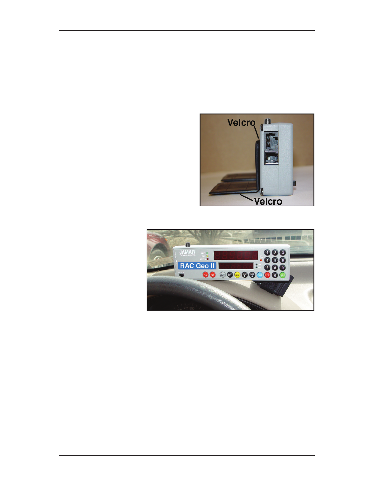
Installing the RAC Geo II should be done with caution as to not cause unsafe conditions.
DO NOT mount the RAC Geo II where it will obstruct the driver's view.
DO NOT mount the RAC Geo II over or near an air bag.
DO NOT route cables in a manner that would interfere with operation of the vehicle.
LIMITED WARRANTY
JAMAR Technologies, Inc. warrants the RAC Geo series instruments for a period of
five (5) years limited warranty against defects in material and workmanship as follows:
first year, parts and labor; years two through five, parts only, flat labor charge. Sensors,
cables, connectors, brackets and other hardware are warranted for ninety (90) days. Refer
to Chapter 2 for information on proper installation and use of the hardware.
JAMAR Technologies, Inc. warrants each new instrument manufactured by the company
to be free from defective material and workmanship and agrees to remedy any such defect.
At its option, it may furnish a new part in exchange for any part of any instrument of its
manufacture which, under normal installation, use and servicediscloses such defect. The
instrument must be returned to the JAMAR factory or authorized service agent intact,
for examination, with all transportation charges prepaid.
This warranty does not extend to any products which have been subject to misuse,
neglect, accident, incorrect wiring not our own, improper installation or use in disregard
of instructions furnished by JAMAR. This warranty does not extend to products which
have been repaired or altered outside the JAMAR factory or authorized service agent.
In no event shall JAMAR Technologies, Inc. be liable for any damages arising from the
use of this product including damages arising from the loss of information.
This warranty is in lieu of all other warranties expressed or implied and no representative
or person is authorized to assume for JAMAR Technologies, Inc. any other liability in
connection with the sale or use of JAMAR products.
JAMAR Technologies, Inc. reserves the right to make improvements on the product and/
or specifications at any time without notice. Questions concerning this warranty or any
JAMAR Technologies, Inc. product should be directed by e-mail, mail or telephone to:
JAMAR Technologies, Inc.
1500 Industry Road, Suite C, Hatfield, PA 19440
Copyright 2018 by JAMAR Technologies, Inc.

iii
Volume 2.6 August 2018
If you have any questions about the use of the RAC Geo II, please call
the following number:
1-215-361-2244
Monday — Friday, 8:00 AM to 5:00 PM Eastern time
You may also contact us by e-mail at:
For more information on our products, or for the latest news in product
development, visit our web site at:
www.jamartech.com
For support information specific to RAC devices, go to:
www.jamartech.com/RACSupport.html
Address any correspondence to:
JAMAR Technologies, Inc.
1500 Industry Road, Suite C
Hatfield, PA 19440
We are pleased that you have chosen the RAC Geo II for your distance measuring
needs. We have strived to develop a unit that is easy to use and has the options that
our customers require. The RAC Geo II has undergone extensive testing to verify
the accuracy of its operations, and each unit is tested before it leaves our facility.
However, just like other complex electronic devices, problems can occur. We always
suggest that users verify the continuing accuracy of any device they use. Should you
detect any problems with any of our products, please notify JAMAR Technologies
immediately and discontinue use of the unit until we have verified its operation.

RAC Geo II User’s Manual
iv
Table of Contents
Technical Support ........................................................... iii
Quick Start Guide & Introduction to the RAC Geo II................... 1-1
Quick Start ......................................................... 1-2
What is the RAC Geo II? ........................................................ 1-3
How Does it Work? ......................................................... 1-3
Installation ......................................................... 2-1
Installing the RAC Instrument ................................................ 2-2
Connecting Power to the RAC Instrument ............................. 2-3
Installing the External Antenna............................................... 2-4
Start Up, Key Functions & Menu Options ...................................... 3-1
Power On ......................................................... 3-2
GPS Sensor Mode Start Up .................................................... 3-3
Key Functions ......................................................... 3-4
Menu Functions ......................................................... 3-7
Additional Features ....................................................... 3-25
External Sensor Mode ......................................................... 4-1
GPS Sensor or external sensor... which is right for you?........ 4-2
Switching from GPS Mode to External Sensor Mode............ 4-3
Installation ......................................................... 4-4
Before You Begin ......................................................... 4-4
Installing External Distance Sensor........................................ 4-5
Installing the RAC Instrument & Antenna.............................. 4-5
Automatic Calibration Procedure ........................................... 4-6
If Your RAC Fails to Calibrate................................................ 4-9
Manual Calibration Procedure .............................................. 4-11
Troubleshooting ......................................................... 5-1
Frequently Asked Questions ................................................... 5-2
Appendix ........................................................ A-1
Connection and Output Formats ............................................ A-2
RAC Geo II Specifications..................................................... A-3
Glossary ........................................................ A-4
Vehicle Calibration Record.................................................... A-6

Chapter 1 — Introduction
1-1
Chapter 1
Quick Start Guide &
Introduction to the
RAC Geo II

RAC Geo II User’s Manual
1-2
Quick Start
Step 1 Install your RAC Geo by mounting it on or near your dash and
plugging in the Geo's auto adapter power supply into your vehicle's 12V
outlet. Screw the GPS antenna into the top of the unit and mount the antenna
on the roof of your vehicle. Note that the antenna is not required, but is
recommended for best accuracy and quickest GPS lock.
Step 2 Perform a test measurement with your vehicle. Once your RAC
has been installed, you should perform a test measurement over a known
distance. This will ensure that the instrument is working correctly. To do
a test measurement, drive to your starting point and stop. Turn on the Geo
and wait for it to acquire a GPS signal, as described below.
When first powered on, the Geo will display GPS FO in the upper display
and begin to look for GPS satellites. This will switch to GPS F1 in about
60 seconds.
A 0will then be shown in the upper display while CH is shown on the lower
display. Next, press the CH (count hold) button to release the instrument
from count hold and then drive the distance to be measured. Stop and/or
press the CH button once you reach the end of the distance to be measured.
Step 3 Familiarize yourself with the features and options of the RAC
Geo II. Refer to Chapter 3 for more detailed instructions on the functions
and procedures of the unit. We recommend that you practice using the RAC
Geo before attempting to use the instrument on a job to be sure you are
comfortable with how to operate it.

1-3
Chapter 1 — Introduction
What is the RAC Geo II?
The JAMAR Technologies Road Analysis Computer (RAC) Geo II is an
accurate, easy-to-use distance measuring instrument (DMI) that incorporates
GPS technology.
The RAC Geo II has been designed with features to provide you with
a versatile and functional instrument that can be learned in a very short
time. This cost-effective unit saves time & money by allowing personnel
to measure distance, accurate up to 1 foot per mile, while recording GPS
coordinates of roadway features.
How does it work?
The RAC Geo II has an on-board GPS receiver built into the unit. Once it
locks onto the GPS satellites, it can track movement. Power is provided
by a 12V auto adapter, which makes the unit completely portable from
vehicle to vehicle. (Power can also come from any existing DMI power
wiring if you already have this.)
While the on-board GPS receiver will track distance, we recommend the
use of the external GPS antenna for the best accuracy. This screws into the
top of the Geo II and comes with the unit.
Accuracy using GPS-based distance measuring is approximately 1 foot
per 1000 feet. If you require greater accuracy, an external distance sen-
sor (such as a modular or magnetic sensor) can be used with the unit to
provide accuracy up to 1 foot per mile (5280 feet). Information on using
an external distance sensor can be found in Chapter 4.
In addition to distance measuring, the RAC Geo II also has the unique
ability to track and store GPS coordinates using the on-board GPS re-
ceiver. The GPS coordinates of road features (intersections, bridges, signs,
guardrails, etc.) can then either be internally stored for download to the
RACPro software, or read directly off the RAC's display.

RAC Geo II User’s Manual
1-4

Chapter 2 — Installation
2-1
Chapter 2
Installation

RAC Geo II User’s Manual
2-2
Installing the RAC Instrument
The compact case design of the RAC Geo allows mounting of it in a num-
ber of convenient locations. Popular locations include on the front of the
dashboard, above or below the dashboard, or on the windshield using the
optional windshield mounting bracket. Wherever you decide to mount the
instrument, remember it should be within easy reach and the display should
be visible without obstructions.
It is most common to mount the RAC
to the front of the dashboard using
the Velcro provided. Two plastic 'L'
brackets are also provided to facilitate
mounting to the top of the dashboard if
that is your preferred location. For best
results, attach the 'L' bracket so that the
bottom of the 'L' is facing away from the
RAC as shown in figure 2.1.
Using the two 'L'
brackets allows you to
compensate for curved
dashboards even if it
requires the RAC to be
mounted on a left or
right slope.
Note: While the RAC
Geo II is designed to
withstand very high temperatures, we recommend disconnecting the RAC
and storing it in the glove box or below the dash if the vehicle will be left
for long periods of time in direct sunlight and high temperatures.
Fig. 2.1 - 'L' Bracket Side View
Fig. 2.2 - 'L' Bracket on Curved Dashboard

Chapter 2 — Installation
2-3
Connecting Power
to the RAC Instrument
After mounting the RAC, plug the Geo's auto adapter power supply into
your vehicle's 12V outlet and connect the other end to the PWR port on the
RAC Geo, as shown below.
You may want to consider allowing enough slack in the cable to permit a
passenger to hold/operate the RAC if necessary. Regardless of the mounting
location, Velcro strips are provided for quick, easy mounting & removal
of your RAC.
*****WARNING*****
When disconnecting the power adapter, be sure to grasp the base of
the adapter while pulling it out, as shown below. Failure to do this may
result in damage to the adapter.
Fig. 2.3 - Connecting Power
Fig. 2.4 - Proper Disconnection of Power Adapter

RAC Geo II User’s Manual Chapter 2 — Installation
2-4
Installing the External Antenna
The RAC Geo comes with an external GPS antenna that screws into the top
of the Geo. Note that the antenna is not required when using the Geo, but
it is recommended for best accuracy and quickest GPS lock.
To use the antenna, screw it into the top of the RAC Geo, being sure to get
a tight connection. Once screwed into the unit, route the antenna to the roof
of your vehicle. The antenna has a magnetic base, so it will attach itself to
any metal.
Note that it is recommended that you do not touch the metal antenna con-
nection while a count in progress as this can interfere with the GPS signal.
Fig. 2.5 - Using the External Antenna

Chapter 3 — Start Up, Key Functions & Menu Options
3-1
Chapter 3
Start Up,
Key Functions
& Menu Options

RAC Geo II User’s Manual
3-2
Your RAC Geo DMI has been designed for simple operation, using large
individual keys which provide a click and tone feedback.
The two 6-digit high-intensity LED display windows allow flexibility in
displaying data to you. The upper, larger display window (referred to as
D-1) is primarily used to display distance. It is also used to indicate menu
locations, time and GPS coordinates. The lower, smaller display window
(referred to as D-2) is used to display count status, speed, interval distance,
menu descriptions, event codes, GPS coordinates, etc.
Power On
This is the slide switch which provides power to the RAC Geo.
When turned on, the RAC will go into start-up mode, which
will vary depending on if the unit is set to GPS sensor mode
or external sensor mode (refer to chapter 4). OFF/ON
Fig. 3.1 — RAC Geo Key Layout

Chapter 3 — Start Up, Key Functions & Menu Options
3-3
GPS Sensor Mode Start-Up
When starting in GPS Sensor mode, the RAC Geo will Display GPSSen in
D-1, indicating it is set to GPS Sensor Mode. It will then switch to display
GPS FO in D-1 and SEnSor in D-2 and begin to look for GPS satellites.
The RAC Geo will display GPS F1 in D-1 once it has found a minimum
number of satellites for a GPS signal (usually in less than 60 seconds).
Once the RAC Geo has reached an F1 lock the Geo will set itself in Count
Hold with CH displayed in D-2 and 0displayed in D-1. At this point, the
Geo is ready to start counting or access menu functions.
Fig. 3.2 —
GPS Sensor Mode Start-Up
Fig. 3.4 — GPS Satellites Found Fig. 3.5 — Ready to Start
Fig. 3.3 —
Looking for GPS Satellites
Once F1 is achieved, the Geo is ready to start, but it will continue to try to
find more satellites in the background. Also during start up, the RAC Geo
will perform some behind-the-scenes functions including: set the unit of
measuring (feet, mile, meter) and the vehicle number to be the last one used
when the RAC was turned off, set itself to count up, and set the Distance
Pulse Output interval to zero.

RAC Geo II User’s Manual
3-4
Key Functions
The Count Hold key will start or stop the computation of dis-
tance pulses. When in Count Hold, CH will be displayed in
D-2 and the RAC will not accumulate any distance. If speed is
also being displayed, it will continue as CH does not stop the
computation of vehicle speed. When released, CH in D-2 will
go out and distance computation will resume.
Display Hold will stop the display from updating while the
RAC will continue to accumulate distance internally. When
in Display Hold, DH will be displayed in D-2. If speed is also
being displayed, it will continue as DH does not freeze the
speed display. Note: You cannot put the RAC in both Count
Hold and Display Hold at the same time. Count Hold will take
precedence over Display Hold.
The Unit key allows you to select the desired unit of measure-
ment. This can be selected/changed while moving or at rest.
When pressed, the distance will cycle from total feet to miles to
kilometers/meters. The LEDs to the left of D-1 indicate which
unit is currently being used.
The Speed key allows you to turn on or off the display of speed
(mph or kph) in D-2. The display of speed is not interrupted by
either the Count Hold or Display Hold keys.
Count
Hold
Display
Hold
Unit
Speed

Chapter 3 — Start Up, Key Functions & Menu Options
3-5
The Menu key allows you to select from a variety of functions.
After pressing the Menu button, the Add and Sub keys can be
used to scroll through the options, which are displayed in D-2.
To select an option, press the ENT (Enter) key. The options are:
Menu 1 - Auto Calibration (A-CAL)
Menu 2 - Manual Calibration (E-CAL)
Menu 3 - Pre-Distance (P-diS)
Menu 4 - Clock Set (CLoSEt)
Menu 5 - Distance Pulse Output (dPO)
Menu 6 - Memory Store (StorE)
Menu 7 - Memory Status (StAtUS)
Menu 8 - Memory Erase (ErASE)
Menu 9 - Store GPS (Str-g)
Menu 10 - Track GPS (Str-t)
Menu 11 - Display GPS (gPS-n)
Menu 12 - Format GPS (gPS-Fo)
Menu 0 - Return to Normal Operation (rEturn)
See pages 3-6 to 3-24 for specific menu instructions.
Menu

RAC Geo II User’s Manual
3-6
The Add key instructs the RAC to count up. It is also used in
the Menu function to scroll up through the various options, and
is used in the Pre-Distance function.
The Sub key instructs the RAC to count down. When in this
mode, the LED indicator for the active unit of measurement
will flash to indicate that you are subtracting distance. Should
you count down to zero (0), the RAC will provide a tone and
automatically begin counting up.
The Sub key is also used in the Menu function to scroll down
through the various options, and is used in the Pre-Distance
function to subtract a desired distance from the displayed
distance.
The Dim key allows you to select from four (4) levels of display
brightness to best suit the ambient light conditions. Full bright
is best for daylight conditions while full dim may best suit night
conditions. Each time the Dim key is pressed, the brightness
will drop one level until the lowest level is reached. It will then
jump back to the high brightness level. Both D-1 and D-2, as
well as the LED indicators, are controlled by the Dim key.
The Clear key is normally used to clear the D-1 distance display
as well as the Interval Distance in D-2 if that function has been
selected. Clear can be used on the run (while measuring), which
allows you to establish a zero starting point without having to
stop your vehicle in traffic or the center of a busy intersection.
Clear will not reset the Time Counter in normal mode.
The Enter key instructs the RAC to accept the previously keyed
value currently on the display. It is also used in the Menu func-
tion and Interval Distance application.
The numeric keys are used to identify menu options and select
numbers desired for calibration, pre-distance, distance pulse
output, clock set, etc.
Subtract
Dim
Clear
Enter
Numbers
0 - 9
Add

Chapter 3 — Start Up, Key Functions & Menu Options
3-7
Menu Functions
The Menu key allows you to select a variety of functions. After pressing the
Menu button, the Add and Sub keys can be used to scroll through the options,
which are displayed in D-2. To select an option, press the ENT (Enter) key.
Menu 1 & 2 - Calibration Procedures
Calibration is only required when using an external distance sensor. Refer to
Chapter 4, External Distance Sensor, for details on calibration procedures.
Menu 3 - Pre-Distance
The Pre-distance feature will allow you to enter a known distance starting
point other than zero. It could be where you left off before lunch, or just
beginning at a known station. This feature also allows you to Add or to
subtract off a distance currently on display in D-1.
Note: The RAC must be in Count Hold to use Pre-Distance.
Step 1
Press the Menu key, the #3 key then
the Enter key. At this point, the unit is
ready to have a distance entered.
Step 2
Using the numeric keys, key in the
desired distance (up to 6 digits), then
press Enter.
Step 3
Press Enter to return to the initial menu
screen, then press Enter again to exit
the menu function. You are now back
in the normal mode with the distance
set to the value you entered.
Note: If you just want to add to the
distance already on display in D-1, in
Step 2, rather than pressing Enter, press
the Add key. To subtract from the current distance, press the Sub key.
Fig. 3.6 — Enter Pre-Distance
Fig. 3.7 — Distance Entered
Fig. 3.8
Normal mode w/ Pre-distance set

RAC Geo II User’s Manual
3-8
Menu 4 - Clock Set
The RAC Geo will compute & display time as either elapsed time from
when the instrument was powered up, or real time if the timer has been set.
The timer starts automatically at zero when the RAC is powered-up. Time
is displayed in D-1 as hh.mm.ss.
To View Elapsed Time:
Press the Menu key, then the #4 key,
then the Enter key. D-1 shows the
elapsed time since the RAC was pow-
ered on. At this time you can stop and
reset the timer with the CLR (clear)
key or just let it continue to run. To re-
turn to normal mode, press the Menu key then the Enter key.
To Set Timer to Real-Time:
Step 1
Press the Menu key, then the #4 key, then the Enter key. D-1 shows the
elapsed time since the RAC was powered on, as shown in Figure 3.9 above.
Step 2
Press the Clear key. Using the number
keys, key in the time you wish to dis-
play (hh.mm.ss format). This can be
either 12 or 24 hour format (i.e 1 PM
= 13 hrs).
Step 3
Wait until the keyed in time is reached
and press the Enter key to begin the
clock counting.
Step 4
To return to normal mode, press the
Menu key then the Enter key.
Fig. 3.9 — Elapsed Time
Fig. 3.10 — Clock Time Entered
Fig. 3.11
Counting from Entered Time
Table of contents
Other Jamar Measuring Instrument manuals
Popular Measuring Instrument manuals by other brands

Hexagon
Hexagon TESA ALESOMETRE instruction manual

Minipa
Minipa ET-3702 instruction manual

TS-market
TS-market BIK-01AM Operation manual

Grundfos
Grundfos DIT-L Installation and operating instructions

Hanna Instruments
Hanna Instruments HI747 instruction manual

Reed Instruments
Reed Instruments R2310 instruction manual