Jamar RAC-100 User manual

i

RAC-100 and 200 User’s Manual
ii
Technical Support
If you have any questions about the use of the RAC-100 or 200, please call
the following number:
1-215-491-4899
Monday — Friday, 8:00 AM to 5:00 PM Eastern time
You may also contact us by fax at:
1-215-491-4889
or by e-mail at:
For more information on our products, or for the latest news in product
development, visit our web site at:
www.jamartech.com
For support information specific to the RAC-100 or 200, go to:
www.jamartech.com/RACSupport.htm
Address any correspondence to:
JAMAR Technologies, Inc.
151 Keith Valley Road
Horsham, PA 19044-1411
Volume 3.0 March 2002

Table of Contents
Technical Support ............................................................ ii
Introduction to the RAC-100 and 200.............................................. 1-1
What are the RAC-100 and 200?............................................ 1-2
How Do They Work? ......................................................... 1-3
Quick Start Guide ......................................................... 1-4
Installation ......................................................... 2-1
BeforeYou Begin ......................................................... 2-2
Installing the Modular Distance Sensor ................................. 2-3
Installing the RAC Instrument ............................................... 2-7
Calibration ......................................................... 3-1
Automatic Calibration Procedure........................................... 3-2
IfYour DMI Fails to Calibrate................................................ 3-4
Manual Calibration Procedure ............................................... 3-6
Key Functions & Operating Procedures ......................................... 4-1
Key Functions: RAC-100 ....................................................... 4-2
Procedures: RAC-100 ......................................................... 4-5
Interval Distance ......................................................... 4-5
Distance Pulse Output (DPO) .......................................... 4-5
Key Functions: RAC-200 ....................................................... 4-7
Procedures: RAC-200 ......................................................... 4-8
Memory Store ......................................................... 4-8
Memory View ......................................................... 4-9
Memory Clear ....................................................... 4-11
Printing and Serial Port (RS-232) Output...................... 4-12
Wireless Infra Red Remote Option ...................................... 4-15
Troubleshooting ......................................................... 5-1
Error Codes ......................................................... 5-2
Frequently Asked Questions................................................... 5-3
Appendix ........................................................ A-1
Connection and Output Formats............................................ A-2
Specifications ........................................................ A-3
DPU-414 Thermal Printer Operating Procedures ................. A-4
Glossary ........................................................G-1
iii
Table of Contents

RAC-100 and 200 User’s Manual
This page was intentionally left blank.
iv

1-1
Chapter 1
Introduction
to the
RAC-100
and 200
Chapter 1 — Introduction

RAC-100 and 200 User’s Manual
1-2
What are the RAC-100 and 200?
The JAMAR Technologies Road Analysis Computer (RAC) Models 100
and 200 are accurate, easy-to-use distance measuring instruments (DMI)
that use state-of-the-art microprocessor technology. The RAC-100 and 200
DMIs have been designed with features to provide you with a versatile and
functional instrument that can be learned in a very short time.
The RAC-200 contains all of the features of the RAC-100 with the addition
of memory storage and data output. This allows for saving of information
for later download to a computer or printer. The RS-232 port used for down-
loading can also be used to control the unit in a real-time mode from a lap-
top computer.
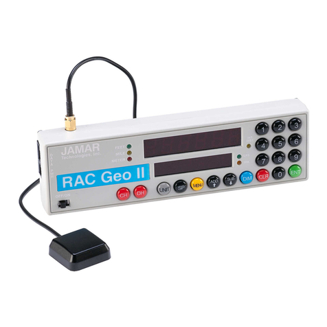
Figure 1.1 — RAC-100 and 200 Distance Measuring Instruments

1-3
Chapter 1 — Introduction
How do they work?
To use the RAC-100 or 200 DMI to accurately measure distance, either a
modular distance sensor (MDS) or mechanical transmission interface
is used to send pulses to the DMI. The Quick-Kit, which is a modified
version of the MDS, can also be used.
Most newer vehicles (1992 and newer) have an electronic distance/speed
sensor inside the transmission which sends pulses to the vehicle's on-board
computer for use in the speedometer,ABS braking system, engine/transmis-
sion control, etc. These vehicle-generated signals can be as many as 100,000
pulses per mile, which is far more than the DMI needs to accurately mea-
sure distance. Further, since the vehicle manufacturers are not concerned
with accurate distance and speed readings at very low speeds (your speed-
ometer may not move below 5 mph), the signal strength at these low speeds
is extremely minimal.
The MDS is not just an improvement over other electronic interface type
sensors. First, and foremost, its proprietary circuitry allows more accurate
slow speed measurements by sensing signals as low as 10 Mv from the
vehicle speed sensor. Second, it is designed to be mounted under the vehicle
dashboard rather than under the hood as with other interface sensors. This
gets the MDS out of a severe heat and moisture environment and into a more
controlled environment. Third, our exclusive internally generated Sensor
Test andTap Test features allow the user to verify proper sensor and instru-
ment operation. Finally, the Modular Design simplifies installation.
Older vehicles with mechanical speedometer cables use the mechanical
transmission sensor, which is screwed on to the transmission. For informa-
tion on how to install this type of sensor, refer to the instructions that came
with the sensor.
The next chapter details how to install a modular sensor into your vehicle.
If your already have a sensor installed, you may skip to Chapter 3 for in-
formation on calibrating your DMI.

RAC-100 and 200 User’s Manual
1-4
Quick Start Guide
The RAC-100 and 200 DMIs will allow you to accurately measure distance
quickly and easily. However, before you can do this a few basic steps must
be taken to ensure that you get the optimum performance from your instru-
ment.
Step 1 Install your DMI and its modular sensor. Refer to Chapter 2 for de-
tailed instructions on this. If you would like to have the equipment
professionally installed, contact a garage or speedometer shop in
your area.
Step 2 Calibrate your instrument. Refer to Chapter 3 for detailed instruc-
tions on how this is done. Your DMI will not accurately measure
distance unless it is properly calibrated.
Step 3 Perform a test measurement with your vehicle. Once your DMI has
been calibrated, you should perform a test measurement over a
known distance.This will ensure that the instrument has been cali-
brated correctly. To do a test measurement, drive to your starting
point and stop. Turn on the DMI and wait until C.H is shown on the
right side of the display and zero is shown on the left side. Next,
press the C Hold (count hold) button to release the instrument from
count hold and then drive the distance to be measured. Stop and/
or press the C Hold button once you reach the end of the distance
to be measured.
Step 4 Familiarize yourself with the features and options of the instrument
that you will be using. Refer to Chapter 4 for more detailed instruc-
tions on the functions and procedures of the RAC-100 or 200.
Step 5 Practice. Before attempting to use the instrument on a job, be sure
you are comfortable with how to operate it.

Chapter 2
Installation
2-1
Chapter 2 — Installation

RAC-100 and 200 User’s Manual
BeforeYou Begin
Note: The following instructions are for installing a RAC with a Modular
Distance Sensor. If you are installing a different type of sensor, refer to the
instructions that came with the sensor itself.
The JAMAR RAC-100 and 200 distance measuring instruments (DMI) are
very reliable instruments. However, there can be some external variables
that could affect proper operation and the ability to accurately measure dis-
tance traveled. By observing a few simple precautions you will be able to
eliminate potential problems.
• Do not install wires near any object that could cause stray pulses to
be picked up, such as the alternator, spark plugs or engine coil.
• Do not install the wires or sensor near any objects that will get hot,
such as the manifold. The installation wires or sensor can melt if they
are too close to a heat source.
• Do not install wires near any objects that could vibrate and cut the
wires.
• Tire pressure should be the maximum suggested by the tire manufac-
turer, typically 32-35 PSI cold. The tire should have ample tread depth.
Steel belted radial tires are highly recommended.
• Drive the vehicle 3 to 5 miles (depending on climate) to warm the tires
up to normal operating temperatures prior to calibrating your DMI.
Refer to Chapter 3, Calibration for more detailed instructions.
2-2

Installing the
Modular Distance Sensor
Most newer vehicles (1992 and newer) have an electronic speed output
rather than a mechanical speedometer cable coming from the transmission.
With the newer vehicles you will need to install either a Modular Distance
Sensor (MDS) Vehicle Kit or a Modular Distance Sensor Quick Kit. Use
the following instructions for installation of the MDS Kits.
1. Find a location under the vehicle
dashboard that will allow fairly easy
access to the MDS. Do Not mount the
MDS on the heater ducts or where the
heater vents will blow directly onto it.
Attach the MDS using the nylon ties
orVelcro provided, as shown in Figure
2.1.
2. Locate the 2 wires coming from the Vehicle’s Speed Sensor (VSS).
• On most Ford and Chrysler pick-up trucks, the best place is on the
rear end differential housing using the rear ABS signal.
• On General Motors pick-up trucks, the best place is the VSS at the
transmission.
• On many vehicles (both trucks and autos) you can go to the cruise
control signal or to the vehicle ECU which is often located under the
dashboard.
(Your localAuto/Truck dealer can usually tell you
where the VSS can be located on your vehicle. If
you need additional assistance, contact JAMAR.)
3. Route the red and black end of the 20’ grey
VSS cable through the firewall. This can usually be done by using an exist-
ing rubber grommet where other wires pass through the firewall. If you
cannotlocatean existing hole,CAREFULLYdrillasmall holelargeenough
for both theVSS cable and the +12Volt/Ground wires. EXTREME CAU-
TION must be taken to insure you do not drill into anything mounted on
the opposite side of the firewall or cut any existing wiring.
2-3
Chapter 2 — Installation
All wires and the
MDS itself should be
kept away from any
heat source that
could cause melting.
Figure 2.1
MDS Mounted Under Dash

RAC-100 and 200 User’s Manual
2-4
Use the cable ties provided while routing the cable to the location for get-
ting the speed signal that you previously identified. Attach the red and
black wires of the VSS cable to the vehicle’s speed sensor wires using the
tap splice connectors provided. The red wire goes to the high-speed signal
wire; the black goes to the low speed signal wire.
NOTE: The tap splice connectors are supplied for convenience for initial
installation. However, we recommend that once the installation is com-
pleted and you have verified the instrument is working properly, remove
the tap splice connectors and solder the connections. Insulate using elec-
trical tape or silicone.
4. Plug the connector of theVSS cable
into the hole labeled VSS Input located
on the right side of the MDS, as shown
in Figure 2.2.
5. Route the black DMI cable from the MDS to the desired instrument
location. This will usually be routed between the doorpost and the dash-
board. Make sure the cable will not be pinched when closing the door. If
the instrument is going to be mounted to the front of the dashboard, you
may want to bring the cable straight up the front of the dash. There is
adequate cable length to allow mount-
ing the DMI in any desired location
inside the vehicle. Plug the cable into
the MDS jack labeled To DMI, as
shown in Figure 2.3. It does not matter
which end of the cable is plugged into
the MDS or DMI.
6.Route the Red (+12Volts) and Black
(Ground) power cables directly to the
vehicle’s battery. This can be done us-
ing the same feed through location that
was used for the VSS Cable. If, out of
convenience, you elect to obtain the
+12VDC and ground from a fuse panel
or other location under the dashboard, make sure it is a constant 12 volt
source and not one that is switched off with the ignition key. We also
recommend the circuit should have as few devices as possible to avoid
Figure 2.2 –VSS Plug-in
Figure 2.3 –DMI Plug-in
Figure 2.4 –Power Plug-in

2-5
Chapter 2 — Installation
voltage fluctuations from Turn Signals, Brake Lights, etc. Plug the power
cable into the hole labeled Power on the MDS, as shown in Figure 2.4.
A diagram of the complete installation for the MDS is shown in Figure 6
on page 2-6.
Adjusting the Vehicle Speed Sensor Pulse Rate
The signal pulses coming from the vehicle speed sensor are generated for
use by the vehicle’s computer, engine/transmission control, fuel manage-
ment, ABS brakes, etc. The pulse rate can vary from 4,000 to in excess of
100,000pulses permile.The MDSwill
condition and amplify these pulses for
use by the DMI. Since the higher pulse
rates are not required for accurate dis-
tance measurements, the MDS incor-
porates a divider circuit to reduce the
pulse rate. This is done by adjusting
the rotary switch on the front of the
MDS, as shown in Figure 2.5.
Although your particular vehicle may vary, generally Chrysler and Ford
vehicles use a 4 to 1 ratio (position 4 on the switch) while General Motors
vehicles use a 16 to 1 ratio (position 16 on the switch). To adjust the ratio,
use a small screwdriver to rotate the switch until the slot in the switch
points to the desired ratio. Note that when the switch is turned counter-
clockwise until it stops, it is at the 1 to 1 ratio.
The adjustments go from 1 to 1 (1 pulse into the sensor, 1 pulse out) through
64 to 1 (64 pulses into the sensor, 1 pulse out). The Tap Test positions are
explained in the troubleshooting section on page 3-4. You may need to
adjust the ratio again based on the results of the calibration procedure de-
scribed in Chapter 3.Any time you change the pulse ratio, you will need to
re-calibrate the DMI.
Once you have installed the MDS, install your RAC 100 or 200 using the
instructions on page 2-7.
Figure 2.5
Rotary SwitchAdjustment

RAC-100 and 200 User’s Manual
2-6
The number of pulses per mile from
avehicle willvarywiththe makeand
model. Your calibration factor
shouldbebetween .500 and1.200.
If not, adjust the rotary switch then
recalibrate to reach a calibration
number within this range.
Note: If the speedometer does not
respond to vehicle movement, sim-
ply reverse the RED and BLACK
wires to correct polarity.
Most vehicles should have a 2-wire output from theVSS.
Dodge & Fordtrucks may have theVSS located on top of the
rear end housing instead of at the transmission. It will nor-
mally be a 2-wire output, small gauge wire.
Connect the red and black wires of the long 20’VSS cable to
the wires from the vehicle’s speed sensor. Crimp-on tap splice
connectors are supplied for convenience on initial installation.
However, we recommend removing the tap splice connectors
and reconnecting using wire to wire solder once you are sure
all connections to the VSS are proper. Insulate with sealant/
electrical tape as needed.
Figure 2.6 –MDS Installation Diagram
Vehicle Speed
Sensor (VSS)
Fire
Wall
Fire
Wall
Tap Splice
Connectors
Battery
DMI Connector
Fuse
Ground Black
+12 VDC
Red

Installing the RAC Instrument
The compact case design of the RAC-100/200 allows mounting of it in a
number of convenient locations. Popular locations include on the front of
the dashboard, above or below the dashboard, or on the windshield using
the optional windshield mounting bracket. Wherever you decide to mount
the instrument, remember it should be within easy reach and the display
should be visible without obstructions.
After mounting the RAC, plug the black cable from the MDS into the DMI.
You may want to consider allowing enough slack in the cable to permit a
passenger to hold/operate the RAC if necessary. Regardless of the mount-
ing location, velcro strips are provided for quick, easy mounting & removal
of your RAC.
Once you have mounted your RAC and connected it to the MDS, proceed
to the calibration instructions in the following chapter.
2-7

RAC-100 and 200 User’s Manual
2-8
This page was intentionally left blank.

Chapter 3
Calibration
3-1
Chapter 3 — Calibration

RAC-100 and 200 User’s Manual
Automatic Calibration Procedure
In order to accurately measure distance, your RAC-100/200 must know the
exact distance that the vehicle will travel based on pulses from the vehicle's
transmission. The calibration number is the automatic calculation that rep-
resents the number of pulses received over a set distance. This number, once
calculated, will remain accurate for any instrument requiring a calibration
factor until a change to the vehicle occurs, such as different size tires put
on the vehicle, tire wear, air added to the tires, etc. At that time, you must
re-calibrate.
In order to calculate the calibration number for
your particular vehicle, you must first establish a
calibration course. The length of the course can
be any known distance more than 500 feet —
1000 feet is ideal. In general, a shorter more pre-
cise course is better than a longer imprecise
course. Your course should be straight and accurate, so take the time to
measure the course using a 100' tape. Mark the beginning and ending points
so they can be seen from inside your vehicle. Remember, the course length
can be any accurate distance over 500 feet, so for convenience you could
use a telephone pole or other marker as reference point.
Step1 SlidetheON/OFFswitchtoON.YourDMIwillperformabrief
SelfTest.ThecurrentCalibrationNumberwillbedisplayedfor
approximately three seconds, then [C.H 0.000] will appear
with the decimal between the C& Hflashing.
Step 2 Align your vehicle to the marker at the beginning of the course
using a reference point on or in the vehicle, such as a window
post, door handle, your shoulder, etc.
Step 3 PresstheUNITkeytoselectfeet.TheFEETLEDwillcomeon
and [ 0 ] will be displayed.
Step 4 Press the CAL key. [CL 0] will show up. The instrument is
asking for the Course Length. Key in the length of your
calibration course in feet using the numeric keypad and press
the ENTER key. [C.H 0] is again on the display. Press the
C-HOLD key, C.H will go off.
Your RAC 100/200
must be calibrated in
order to accurately
measure distance.
3-2

Step 5 Drive the calibration course. The count you see represents the
pulses seen from your transmission sensor and not the distance
beingtraveled,sodon'tpanicwhenthedisplaydoesn'tequalthe
actual length of your course.
Step 6 When you reach the end of the course, stop your vehicle so that
youareexactlyalignedwiththeendmarkerusingthereference
pointonthevehicleusedatthebeginningofthecoursePressthe
C-HOLDkeyandC.Halongwiththepulsescountedwillbeon
thedisplay.PresstheCALkeyandCFalongwiththecomputed
calibration number will be displayed. Record this number for
future reference. Press the ENTER key. Your calibration num-
berisnowstoredintheDMI'snonvolatile(permanent)memory
and [C.H 0] is displayed. The
calibration number will stay in
memoryfor morethan40 years until
you re-calibrate or manually change
the calibration number. You are able
to view the current number every
time you power on the DMI.
You should rerun the calibration course to verify the calibration for your
vehicle. Press C-HOLD prior to measuring. If this is the first time you have
calibrated a DMI, you may want to run the course a couple of times to prac-
tice being properly aligned when starting and stopping at the course mark-
ers.
The calibration number used should be between .500 and 1.200. If your
calibration number is below this range, you need to use a higher division
factor (such as 1 to 16 or 1 to 32) by adjusting the
rotary switch on your MDS. Of course, if the cali-
bration number is too high, use a lower division
factor (such as 1 to 1 or 1 to 2). Refer to the Ad-
justing the Vehicle Speed Sensor Pulse Rate sec-
tion in Chapter 2 for more information on this.
Several calibration runs may be necessary to de-
termine which division factor is best for your ve-
hicle.
Your calibration
number should be be-
tween .500 and 1.200.
If not, you need to ad-
just the rotary switch
on your MDS.
3-3
Chapter 3 — Calibration
If you RAC does not
count during the cali-
bration procedure,
refer to the trouble-
shooting section on
the next page.

RAC-100 and 200 User’s Manual
IfYour DMI Fails to Calibrate
If your DMI fails to count during calibration, perform the following opera-
tional checks:
Step 1 Locate the Sensor Test button on
the front upper right of the
MDS, shown in Figure 3.1.
When pressed, this will gener-
ate an internal low-level signal
that is fed directly into theVSS
Input circuit. First, unplug the
VSS Input connector from the
right side of the MDS. Second, turn on the DMI and press the C-
HOLD key just like you would prior to starting a measurement.
Next, using a small pointed object (pen, pencil, screwdriver, etc.)
or your finger press the Sensor Test button for a few seconds. The
DMI should count when the button is pushed. What number it
counted doesn’t matter as long as it did count.
If the DMI did count, everything from the MDS up to the DMI is
okay and the problem is most likely either a poor connection at the
vehicle’s speed sensor or the connection is not at the correct loca-
tion to get the vehicle speed signal. The speed sensor output is
generally at the transmission or the rear differential. If you are
unsure about being attached to the correct output, disconnect the
plug and move the vehicle. If the speedometer does not function,
you have chosen the correct plug wires.
If you are at the correct location, make sure you have a good elec-
trical connection at the tap in point. Once you are sure you tapped
into the correct location, it is always better to wire solder the con-
nection.
After checking the connection, plug theVSS Input connector back
into the MDS and try the DMI again. If the DMI counts, you can
proceed with calibration. If the DMI still does not count, go to
Step 2.
3-4
Figure 3.1 – Sensor Test
This manual suits for next models
1
Table of contents
Other Jamar Measuring Instrument manuals
Popular Measuring Instrument manuals by other brands

Keysight
Keysight N9923A user guide

Sper scientific
Sper scientific 850024 instruction manual

Tektronix
Tektronix Keithley 6517B Reference manual

Agilent Technologies
Agilent Technologies 8564EC Service guide

Schaller
Schaller humimeter BMA user manual

Thermo Scientific
Thermo Scientific NanoDrop 2000 instruction manual

Teledyne Analytical Instruments
Teledyne Analytical Instruments GFC 7002T Operation manual

Heathkit
Heathkit im-5210 instructions

Bellingham and Stanley
Bellingham and Stanley Abbe 60 user guide

GPI
GPI TM Series Operation guide

LaserLiner
LaserLiner AQua-Master operating instructions

Hawk
Hawk OptioLaser L100 manual