Datakom DKM-407 User manual

DKM-407 User Manual V-1.1
1
DKM-407
DIN RAIL TYPE
NETWORK ANALYZER
The DKM-407 is a DIN rail mounted precision
and low cost unit allowing measurement and
remote monitoring of AC parameters of a
distribution panel.
The unit is supplied between L1 and Neutral
terminals. Thanks to the supply range of 85-
305V, it is not affected by voltage fluctuations
and is capable of operating in any network.
The unit features an 32-bit ARM core
microcontroller. With a sampling rate of
4096s/s it reaches 0.5% precision.
The unit provides 1 programmable digital
input and 1 programmable relay output.
Input/output functions are selected from a list.
The isolated RS-485 MODBUS RTU data
port is not affected by ground potential
differences.
Program parameters may be uploaded from
a PC.
● True RMS measurements
●0.5 % measurement precision
● Total harmonic distortion display
● Demand, Min and Max records
● Fully isolated RS-485 serial port
● MODBUS-RTU communications
● Programmable relay output
● Energy pulse output capability
● Isolated, programmable digital input
● kW and kVAr energy counters
●Hours run counter
● VT ratio for medium voltage applications
● Front panel programming
● Wide operating temperature range
● 2 part connectors
FEATURES
DESCRIPTION
MEASURED PARAMETERS

DKM-407 Kullanım Kılavuzu V-1.1
2
Electrical equipment should be installed only by qualified
specialist. No responsibility is assured by the
manufacturer or any of its subsidiaries for any
consequences resulting from the non-compliance to
these instructions.
Check the unit for cracks and damages due to
transportation. Do not install damaged equipment.
Do not open the unit. There is no serviceable parts inside.
Fuses must be connected to phase voltage inputs, in
close proximity of the unit.
Fuses must be of fast type (FF) with a maximum rating of
6A.
Disconnect all power before working on equipment.
When the unit is connected to the network do not touch
terminals.
Short circuit terminals of unused current transformers.
Any electrical parameter applied to the device must be in
the range specified in the user manual.
Do not try to clean the device with solvent or the like.
Only clean with a dry cloth.
Verify correct terminal connections before applying
power.
Current Transformers must be used for current
measurement.
No direct connection allowed.
SAFETY NOTICE
Failure to follow below instructions will
result in death or serious injury

DKM-407 Kullanım Kılavuzu V-1.1
3
Section
1. INSTALLATION
1.1. FRONT PANEL VIEW
1.2. MECHANICAL INSTALLATION
1.3. ELECTRICAL INSTALLATION
2. PUSHBUTTON FUNCTIONS
3. DISPLAY NAVIGATION
4. DEVICE CONFIGURATION
4.1. INTRODUCTION
4.2. RESETTING DEMAND VALUES
4.3. RESETTING ENERGY COUNTERS
4.4. RESETTING THE HOUR COUNTER
4.5. RESETTING ALARMS
4.6. SETTING THE DEFAULT SCREEN
4.7. SETTING THE CURRENT TRANSFORMER RATIO
4.8. SETTING THE VOLTAGE TRANSFORMER RATIO
4.9. SETTING HIGH AND LOW VOLTAGE LIMITS
4.10. SETTING HIGH AND LOW FREQUENCY LIMITS
4.11. SETTING THE OVERCURRENT LIMIT
4.12. SETTING HIGH AND LOW ACTIVE POWER LIMITS
4.13. SETTING HIGH AND LOW REACTIVE POWER LIMITS
4.14. SETTING HIGH AND LOW POWER FACTOR LIMITS
4.15. CONFIGURING THE DIGITAL INPUT
4.16. CONFIGURING THE RELAY OUTPUT
4.17. CONFIGURING THE ALARM DELAY
4.18. MODBUS PARAMETERS
4.19. ENERGY PULSE OUTPUT (kWh, kVArh) PARAMETERS
4.20. DISPLAYING THE FIRMWARE VERSION
4.21. CALIBRATION
4.22. LAMP TEST
5. MODBUS COMMUNICATIONS
5.1. DESCRIPTION
5.2. COMMANDS
5.3. PROGRAM PARAMETERS
5.4. MEASUREMENTS AND CONTROLLER RECORDS
6. TECHNICAL SPECIFICATIONS
TABLE OF CONTENTS

DKM-407 Kullanım Kılavuzu V-1.1
4
Before installation:
Read the user manual carefully, determine the correct connection diagram.
Install the unit to the DIN rail.
Make electrical connections with plugs removed from sockets, then place plugs to their
sockets.
Note that the power supply terminal is separated from measurement terminals.
Below conditions may damage the device:
Incorrect connections.
Incorrect power supply voltage.
Voltage at measuring terminals beyond specified range.
Current at measuring terminals beyond specified range.
Connecting or removing data terminals when the unit is powered-up.
Overload or short circuit at relay outputs
Voltage applied to digital inputs over specified range.
High voltage applied to communication port.
Below conditions may cause abnormal operation:
Power supply voltage below minimum acceptable level.
Power supply frequency out of specified limits
Phase order of voltage inputs not correct.
Current transformers not matching related phases.
Current transformer polarity incorrect.
Current Transformers must be used for current
measurement.
No direct connection allowed.
1. INSTALLATION

DKM-407 Kullanım Kılavuzu V-1.1
5
1.1 FRONT PANEL VIEW

DKM-407 Kullanım Kılavuzu V-1.1
6
Although the unit is protected against electromagnetic disturbance, excessive disturbance
can affect the operation, measurement precision and data communication quality.
ALWAYS remove plug connectors when inserting wires with a screwdriver.
Fuses must be connected to phase voltage inputs, in close proximity of the unit.
Fuses must be of fast type (FF) with a maximum rating of 6A.
Use cables of appropriate temperature range.
Use adequate cable section, at least 0.75mm2 (AWG18).
For current transformer inputs, use at least 1.5mm2section (AWG15) cable.
The current transformer cable length should not exceed 1.5 meters. If longer
cable is used, increase the cable section proportionally.
Follow national rules for electrical installation.
Current transformers must have 5A output.
Current Transformers must be used for current
measurement.
No direct connection allowed.
Do not install the unit close to high electromagnetic
noise emitting devices like contactors, high current
busbars, switchmode power supplies and the like.
1.3 ELECTRICAL INSTALLATION

DKM-407 Kullanım Kılavuzu V-1.1
7
1.4 CONNECTION DIAGRAM

DKM-407 Kullanım Kılavuzu V-1.1
8
Three buttons on the front panel provide access to configuration and measurement
screens.
BUTTON
FUNCTION
Selects display context
THD display
Minimum values display
Maximum values display
Demand display
If all leds are off then actual measurements
display.
HELD PRESSED FOR 5 SEC:
resets min-max values and displays minimum phase-
to-neutral voltages.
Upper screen
or
Increase related value (configuration mode)
Lower screen
or
Decrease related value (configuration mode)
HELD PRESSED TOGETHER FOR 2 SEC:
Enters configuration mode.
IF NO BUTTON PRESSED FOR 5 MINUTES:
returns to the main display screen
2. PUSHBUTTON FUNCTIONS

DKM-407 Kullanım Kılavuzu V-1.1
9
The button will select the display context and buttons will navigate
between possible values of this context.
Kilo/Mega (k/M) led will turn on if the displayed value is in kA/kV/MW/MVA/MVAr.
TOTAL led will turn on when displaying total values.
Normally, the led indicating the values on display will be on. Other leds will turn off. If total
working hours is displayed then only the TOTAL led will turn on.
When displaying voltage, current, THD, power factor, etc.. each display will show the
value related to one phase. When total values are displayed, depending on the length of
the data to display, all 3 displays may be used.
Display of currents: If the greatest current value to display is larger than 999A then the
k/M (kilo/mega) led will turn on, otherwise it will turn off. When the k/M led is off, if the
greatest current value is below 100A then currents will be displayed with 0.1A precision,
otherwise they will be displayed with 1A precision. When the k/M led is on, if the greatest
current value is below 10kA then currents will be displayed with 0.01kA precision,
otherwise they will be displayed with 0.1kA precision.
Display of voltages: If the greatest voltage value to display is larger than 999V then the
k/M (kilo/mega) led will turn on, otherwise it will turn off. When the k/M led is off, voltages
will be displayed with 1V precision. When the k/M led is on, if the greatest voltage value is
below 10kV then voltages will be displayed with 0.01kV precision, between 10kV and
99.9kV they will be displayed 0.1kV precision and above 100kV they will be displayed with
1kV precision.
Display of kW, kVA, kVAr: Depending on the values, they will be displayed with 0.1k or
1k or 0.01M precision.
Display of kWh, kVArh, Hours: Values are displayed with a precision of 0.1 k (or hour).
3. DISPLAY NAVIGATION

DKM-407 Kullanım Kılavuzu V-1.1
10
In order to offer the maximum flexibility to the user, the unit has several configurable
parameters.
Device Configuration
Default display configuration
Measurement Configurations
Resetting Demand Values
Clearing Counters
Resetting Alarms
Setting the CT ratio
Setting the VT ratio
Setting alarm limits
Input / Output Configuration
Input Configuration
Relay Configuration
Alarm delay
Modbus parameters
Device Calibration
In order to enter the configuration menu,
hold both MENU buttons pressed for 2 seconds.
In order to exit the configuration menu,
hold both MENU buttons pressed for 2 seconds.
If no button is pressed, the unit will automatically
close the configuration menu after 1 minute.
Parameter values are increased / decreased with
MENU buttons. Holding the button pressed will
increase / decrease with larger steps.
Pressing the SET button will save the current
parameter and display the next parameter.
Holding the SET button pressed for 2 seconds will
display the previous parameter.
4.1 INTRODUCTION
4. DEVICE CONFIGURATION

DKM-407 Kullanım Kılavuzu V-1.1
11
Parameter value:
0: No action
1: Reset Demand values
Setting this parameter to 1 will reset demand
values.
The parameter value is not stored into
memory and reads always 0.
Parameter value:
0: No action
1: Reset kWh and kVArh counters
Setting this parameter to 1 will reset
powermeter counters.
The parameter value is not stored into
memory and reads always 0.
Parameter value:
0: No action
1: Reset hour counter
Setting this parameter to 1 will reset the
hour counter.
The parameter value is not stored into
memory and reads always 0.
4.4 RESETTING THE HOUR COUNTER
4.3 RESETTING ENERGY COUNTERS
4.2 RESETTING DEMAND VALUES

DKM-407 Kullanım Kılavuzu V-1.1
12
Parameter value:
0: No action
1: Reset alarms
Setting this parameter to 1 will reset
existing alarms.
The parameter value is not stored into
memory and reads always 0.
This parameter selects the default screen
that the unit returns 5 minutes after any
key is pressed.
Setting this parameter to 0 will cancel the
default screen.
Param.
değeri
Göstergeler
0
no change
1
Voltages L-N
2
Voltages L-L
3
Currents
4
Total current
5
Phase kW
6
Total kW
7
Phase kVAr
8
Total kVAr
9
Phase kVA
10
Total kVA
11
Phase cosø
12
Total cosø
13
Frequency
14
kWh counter
15
kVArh counter
16
Hours counter
4.6 SETTING THE DEFAULT SCREEN
4.5 RESETTING ALARMS

DKM-407 Kullanım Kılavuzu V-1.1
13
This parameter sets the primary rating of
current transformers.
Current transformer secondary rating
should be 5 Amps.
The factory set default value is 500/5A.
Acceptable values are 5/5A to 5000/5A.
This parameter sets the ratio of voltage
transformers.
All voltage and power measurements will
be displayed after multiplication with this
parameter.
The factory set default value is 1.0
Acceptable values are 0.1 to 200.0
4.8 SETTING THE VOLTAGE TRANSFORMER RATIO
4.7 SETTING THE CURRENT TRANSFORMER RATIO

DKM-407 Kullanım Kılavuzu V-1.1
14
This parameter sets the high limit for high
voltage alarm.
Only phase to neutral voltages are
monitored and generate alarms.
If the parameter is set to 0 then no high
voltage alarm will occur.
The factory set default value is 0
Acceptable values are 0 to 12’000volts
This parameter sets the low limit for low
voltage alarm.
Only phase to neutral voltages are
monitored and generate alarms.
If the parameter is set to 0 then no low
voltage alarm will occur.
The factory set default value is 0
Acceptable values are 0 to 12’000volts
4.9 SETTING HIGH AND LOW VOLTAGE LIMITS

DKM-407 Kullanım Kılavuzu V-1.1
15
This parameter sets the high limit for high
frequency alarm.
If the parameter is set to 0 then no high
frequency alarm will occur.
The factory set default value is 0
Acceptable values are 0 to 400Hz
This parameter sets the low limit for low
frequency alarm.
If the parameter is set to 0 then no low
frequency alarm will occur.
The factory set default value is 0
Acceptable values are 0 to 400Hz.
This parameter sets the high limit for
overcurrent alarm.
If the parameter is set to 0 then no
overcurrent alarm will occur.
The factory set default value is 0
Acceptable values are 0 to 5000Amps.
4.11 SETTING THE OVERCURRENT LIMIT
4.10 SETTING HIGH AND LOW FREQUENCY LIMITS

DKM-407 Kullanım Kılavuzu V-1.1
16
This parameter sets the high limit for
excess active power alarm.
If the parameter is set to 0 then no excess
active power alarm will occur.
The factory set default value is 0
Acceptable values are 0 to 6500kW.
This parameter sets the low limit for low
active power alarm.
If the parameter is set to 0 then no low
active power alarm will occur.
The factory set default value is 0
Acceptable values are 0 to 6500kW.
4.12 SETTING HIGH AND LOW ACTIVE POWER LIMITS

DKM-407 Kullanım Kılavuzu V-1.1
17
This parameter sets the high limit for
excess reactive power alarm.
If the parameter is set to 0 then no excess
reactive power alarm will occur.
The factory set default value is 0
Acceptable values are 0 to 6500kVAr.
This parameter sets the low limit for low
reactive power alarm.
If the parameter is set to 0 then no low
reactive power alarm will occur.
The factory set default value is 0
Acceptable values are 0 to 6500kVAr.
4.13 SETTING HIGH AND LOW REACTIVE POWER LIMITS

DKM-407 Kullanım Kılavuzu V-1.1
18
This parameter sets the high limit for high
cosø alarm.
If the parameter is set to 0.000 then no high
cosø alarm will occur.
The factory set default value is 0.000
Acceptable values are 0.000 to 1.000
This parameter sets the low limit for low
cosø alarm.
If the parameter is set to 0.000 then no low
cosø alarm will occur.
The factory set default value is 0.000
Acceptable values are 0.000 to 1.000
4.14 SETTING HIGH AND LOW POWER FACTOR LIMITS

DKM-407 Kullanım Kılavuzu V-1.1
19
This parameter sets the active status of the
digital input signal.
0: input active when signal applied
1: input active when signal removed
The input signal is 5 to 30V AC or DC
applied between terminals with the polarity
shown in the connection diagram.
The factory set default value is 0.
This parameter sets the detection delay of
the digital input signal in miliseconds.
This delay is necessary to prevent spurious
signal detection due to electrical noise.
The factory set default value is 1ms.
Acceptable values are 1 to 1000ms.
4.15 CONFIGURING THE DIGITAL INPUT

DKM-407 Kullanım Kılavuzu V-1.1
20
This parameter sets the function of the
digital input.
The factory set default value is 11.
Value
Function when signal active
Function when signal passive
0
kWh and kVArh counters increment
no increment
1
kWh and kVArh counters increment
kWh and kVArh counters reset to zero
2
kWh, kVArh, hour counters increment
no increment
3
kWh, kVArh, hour counters increment
kWh, kVArh and hour counters reset to
zero
4
Hour counter increment
no increment
5
Hour counter increment
Hour counter reset to zero
6
kWh and kVArh counters reset to zero
-
7
Hour counter reset to zero
-
8
kWh, kVArh and hour counters reset to
zero
-
9
Reset alarms
-
10
Turn displays OFF
-
11
-
-
Other manuals for DKM-407
1
Table of contents
Other Datakom Measuring Instrument manuals
Datakom
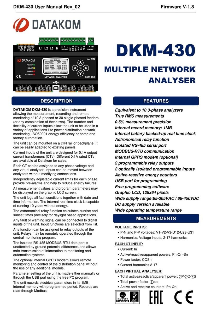
Datakom DKM-430 User manual
Datakom
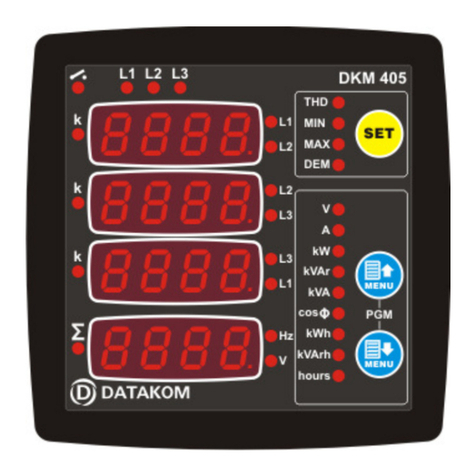
Datakom DKM-405 User manual
Datakom
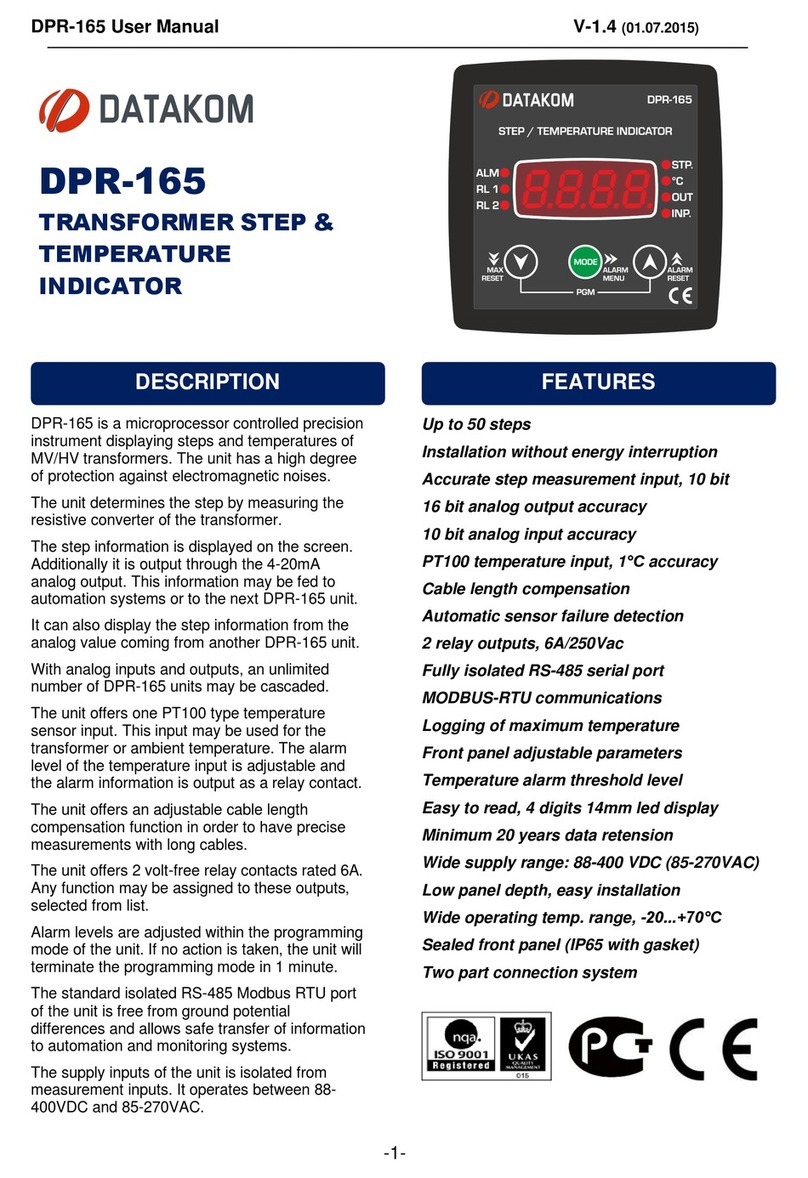
Datakom DPR-165 User manual
Datakom
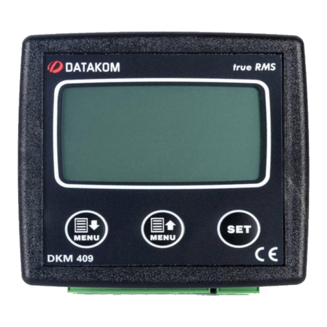
Datakom DKM-409 User manual
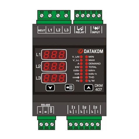
Datakom
Datakom DKM-407 User manual
Datakom
Datakom DSD-080 User manual
Datakom
Datakom DV-0101 User manual
Datakom
Datakom DKM-409-S User manual
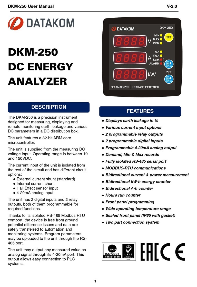
Datakom
Datakom DKM-250 User manual
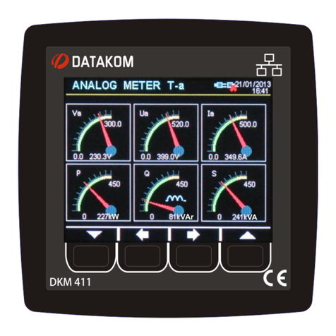
Datakom
Datakom DKM-411 User manual
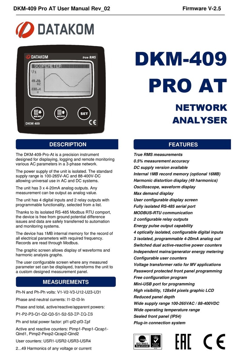
Datakom
Datakom DKM-409 PRO AT User manual

Datakom
Datakom DKM-411 User manual

Datakom
Datakom DKM-411 Instructions for use

Datakom
Datakom DKM-409-PRO-AT User manual
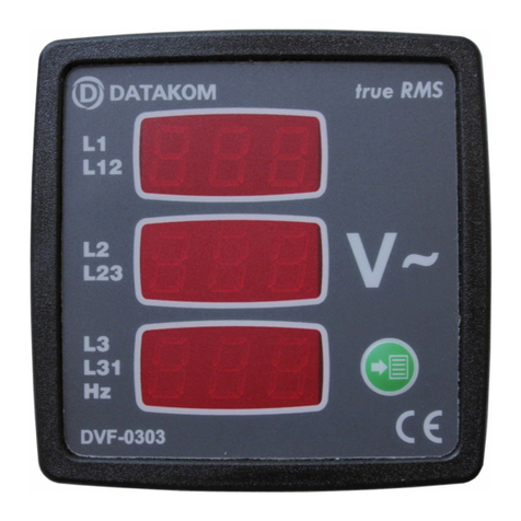
Datakom
Datakom DVF-0303 User manual
Datakom
Datakom DPR-350 Series User manual
Datakom
Datakom DKM-260 User manual

Datakom
Datakom DKM-409 User manual
