J&D MAnufacturing IS275-17L User manual

IS275-17L J&D Manufacturing • 6200 Hwy 12 • Eau Claire, WI 54701 • 1-800-998-2398 • www.jdmfg.com T.O.C.
HPF Stainless Steel Lines
with 12”, 18”, 24”, or 48”
Nozzle Spacing
HPF Stainless Steel
Panel Fan Ring Kit
with 12 Nozzles
High Pressure Fog System
Table of Contents
Warranty & Recommended Tools
Water Quality Requirements
Pump & Filter Kit Location
Requirements & Recommendations
Parts Identification
Guidelines for Assembling Components
Filter System Assembly & Installation
Motor/Pump Shelf Assembly & Installation
Motor & Pump Assembly & Installation
Hanging & Connecting Stainless Steel Lines
J&D Panel Fan Ring Kit Installation
Ring Kit Installation for (36” and Larger) Basket Fans
Cross Kits Installation for Basket Fans
Auto Drain Kit Installation & Assembly
A:
B:
C:
D:
E:
F:
G:
H:
I:
J:
K:
L:
M:
Connecting Pump to Filter and Fogging System/s
Flushing System
Filter Installation
Nozzle Installation
Test & Adjust System
Maintenance
End of Season & Winterizing
Maintenance Checklist
N:
O:
P:
Q:
R:
S:
T:
U:
• Reduces temperatures quickly and uniformly with minimal
energy use
• Minimizes heat stress which improves feed conversion
for increased production
• Easy to retrofit your current ventilation system
• Made from corrosion resistant materials for long life
• Anti-drip brass nozzles with end of line auto drain valve
help keep your floor dry
• Reduces heat stress mortalities

WARRANTY
One year is our standard warranty unless specified on our literature or in the installation instructions/user manuals, for pump warranty see pump manual.
J&D Mfg. warrants all products are free from defects in materials and workmanship under normal use for the period of one year from date of purchase, warranty does not cover normal or regular wear
and tear. J&D Mfg can repair or replace at our option, any product or part of the product that is found to be defective. Our warranty applies to materials only and does not include return freight, delivery,
loss or damage to personal property, cost of removal or installation, any incidental or consequential damages or labor. This warranty does not apply to products which are misused, abused, altered,
improperly installed or subject to negligence. All warranties must be approved through our warranty department. The original purchaser must present a copy of the invoice for the defective product.
INSTALLATION
Please read over all instructions carefully before you begin. If you have any questions please call your local dealer, or contact
J&D Manufacturing at 1-800-998-2398.
IS275-17L J&D Manufacturing • 6200 Hwy 12 • Eau Claire, WI 54701 • 1-800-998-2398 • www.jdmfg.com Section A - Page 1/1
Section A
Warranty & Recommended Tools and SuppliesSection A
RECOMMENDED TOOLS & SUPPLIES FOR INSTALLATION AND ASSEMBLY (NOT PROVIDED)
Safety Glasses
Measuring Tape
Socket Wrench
1/2”
9/16”
Sockets
PVC
Primer / Cleaner
PVC
Glue / Cement
PTFE
Tape
PVC Primer & PVC Glue/Cement
Brushes or Swabs for
PVC Primer & PVC Glue/Cement
if not provided with product
3/8”
Drill Bit
Drill
#3 Phillips
Driving Bit
Flat Head Screwdriver
Crescent Wrench 1/2”
9/16”
3/4”
Combination Wrenches
3 MM Hex Key
Nylon Tube Cutter
IN
OUT
IS275-17L J&D Manufacturing • 6200 Hwy 12 • Eau Claire, WI 54701 • 1-800-998-2398 • www.jdmfg.com Section B & C - Page 1/1
Section B
Water Quality RequirementsSection B
Section C
Filter & Motor Location Requirements & RecommendationsSection C
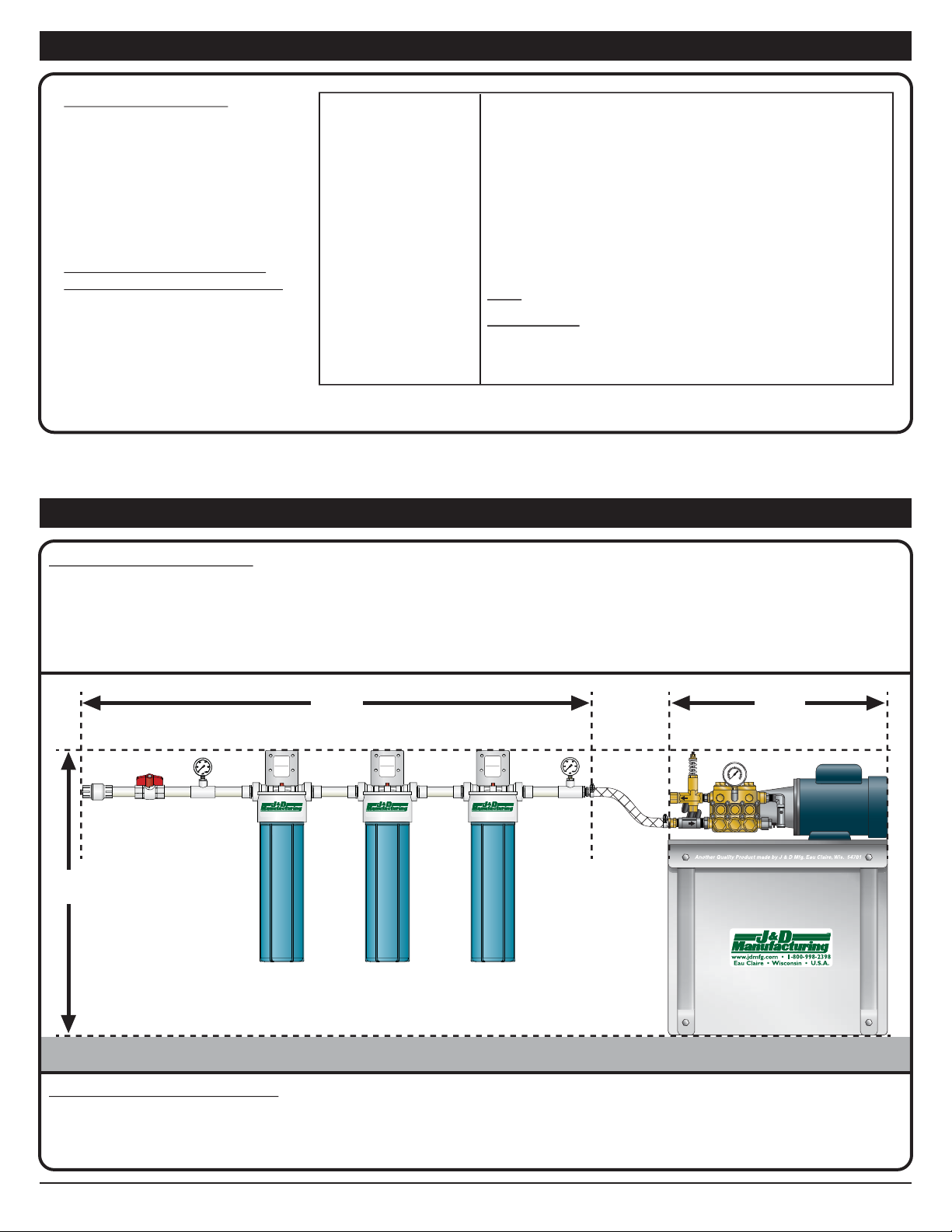
Filter & Motor Space Requirements
The minimum space requirements needed for the filtration assembly are 54” in width and 37” in height
The minimum space requirements for the motor and pump shelf assembly are 31” in width and 37” in height.
Provided 3/4” x 5’ Braided Hose for connecting filter assembly to pump allows for a 4’ distance between the filtration assembly and the motor pump shelf
assembly, however this distance can be extended if a longer (not provided) hose is acquired.
Filter & Motor Space Recommendations
Due to the nature of setup and maintenance of a filtration system, it is recommended that it be located in an area that has a floor drain or is some way protected
so that water will not damage materials or structure. Additional precautions should be taken to ensure that water will not come in contact with electrical cords
or outlets as this may result in severe injury or even death.
Water Quality Requirements
Thorough water testing and treatment of
your intended water supply by qualified
water treatment professionals is required
to minimize mineral deposits and corrosion
that may block or erode nozzles.
Shown are the basic parameters required
of your water supply.
Additional requirements by your water
treatment professionals may be justified.
Damage or clogging of nozzles or
other elements of J&D’s High Pressure
Fogging system due to insufficiently
treated water will not be covered by
warranty.
Test
Hardness
PH
Dissolved Metals
TDS
(Total Dissolved Solids)
Required Parameters
Less than 7gpg
(120 parts per million or milligrams per liter)
7.0 or higher
Listed are the most common and problematic.
Consult with your water specialist on what additional
dissolved metals you may need to correct.
Iron - Less than 0.3 parts per million
Manganese - Less than 0.05 parts per million
Less than 500 milligrams per liter
________________________________________________________
________________________________________________________
________________________________________________________
________________________________________________________
20
Micron
Filter
www.jdmfg.com • 1-800-998-2398
Eau Claire • Wisconsin • U.S.A.
OA128-08K 20
Micron
Filter
www.jdmfg.com • 1-800-998-2398
Eau Claire • Wisconsin • U.S.A.
OA128-08K 20
Micron
Filter
www.jdmfg.com • 1-800-998-2398
Eau Claire • Wisconsin • U.S.A.
OA128-08K
20
MICRON
REPLACEMENT
FILTER
5
MICRON
REPLACEMENT
FILTER
1
MICRON
REPLACEMENT
FILTER
37”
54” 31”
FloorFloor Floor Floor
* Indicates shown to scale for ease of identification.
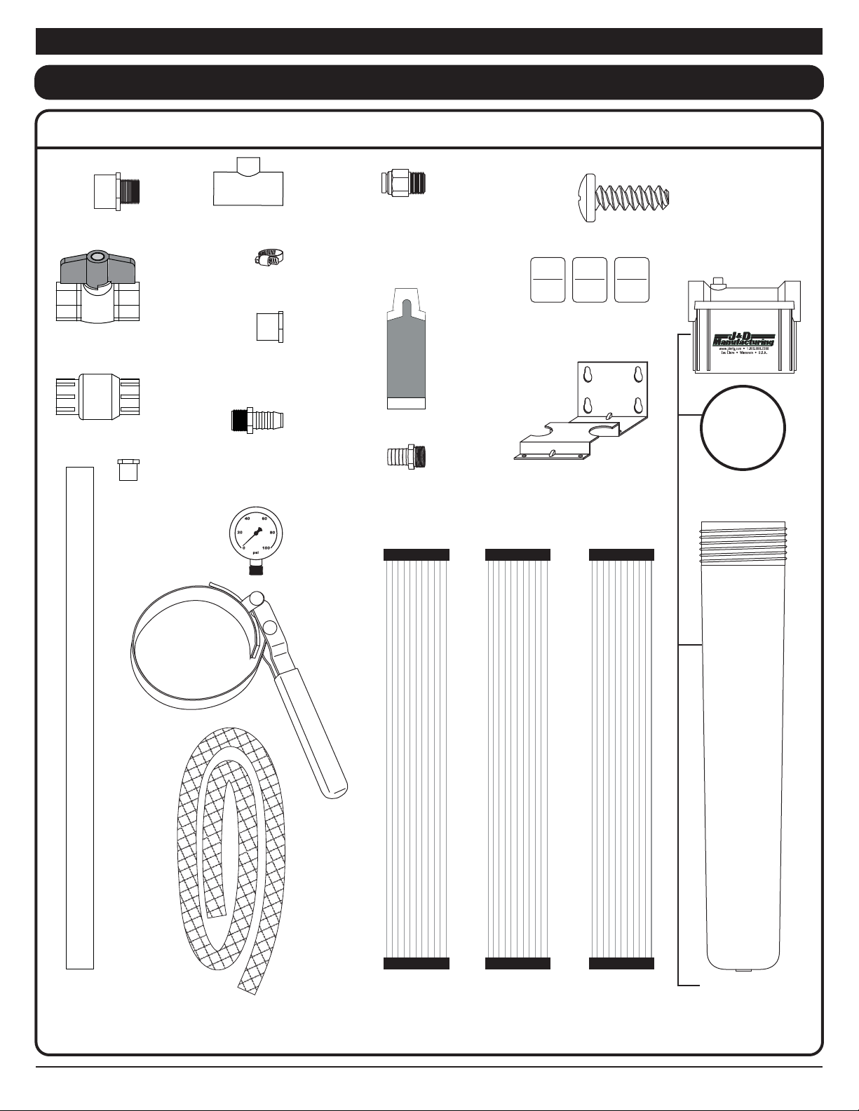
(2)
SS19
1/2”x1/4”
Reducer
(2)
SSOT
1”x1”x1/2”
Tee
(2)
VHPR145
Hose Clamp
(2)
VHPR149
Water Supply
Low Pressure
Gauge
(1)
SS01
1” Ball Valve
(1)
VHPR147
Male Adaptor
3/4” MPT x
3/4” Insert
(1)
VHPR146
1” Spigot x
3/4” FPT
Reducer Bushing
(1)
VHPR151
1” PVC Tubing
2’ Stick
VHPF2520C - 3 Stage 2½” Filter Kit
*(12)
HD10464
Phillips Pan Head Screw
#14–10 x 3/4”
(6)
PP10461
3/4”x1”
Adapter
(1)
VHPR138
1 Micron
2-1/2” Filter
(1)
VHPR137
5 Micron
2-1/2” Filter
(1)
VHPR136
20 Micron
2-1/2” Filter
(3)
VHPR142
Mounting Bracket for
2-1/2” Filter Housing
(1)
VHPR133
2-1/2” Filter
Housing
Wrench
(3)
VHPR135
2-1/2” Filter
Housing Assembly
20
MICRON
REPLACEMENT
FILTER
5
MICRON
REPLACEMENT
FILTER
1
MICRON
REPLACEMENT
FILTER
Set of 3 Filter Size Labels
for Mounting Brackets
SS05R
O-Rings for
2-1/2” Filter Housing
IS275-17L J&D Manufacturing • 6200 Hwy 12 • Eau Claire, WI 54701 • 1-800-998-2398 • www.jdmfg.com Section D - Page 1/8
Section D
Parts IdentificationSection D
(1)
SS03
1” One Way
Check Valve
(1)
VHPR148
Brass Adaptor
3/4” ID Barb x
3/4” Male
Hose Thread
(1) PP10815
Anti-Seize
Lubricant
2 Gram
Single Use
Pouch
(1)
VHPR152
3/4” Braided Hose
5’ Length
(1)
VHPR123
Adapter
3/8” Slip Lock
x 3/8” MIPT

(1)
VHPR151
1” PVC Tubing
2’ Stick
(1) PP10815
Anti-Seize Lubricant
2 Gram
Single Use Pouch
(1)
VHPR140
20 Micron
4-1/2” Filter
(3)
VHPR139
4-1/2” Filter
Housing Assembly
(1)
VHPR144
5 Micron
4-1/2” Filter
(1)
VHPR141
1 Micron
4-1/2” Filter
(1)
VHPR132
4-1/2” Filter
Housing Wrench
(6)
VHPR143
1”x1” Adapter
(2)
SS19
1/2”x1/4” Reducer
(2)
SSOT
1”x1”x1/2” Tee
(2)
VHPR145
Hose Clamp
(2)
VHPR149
Water Supply
Low Pressure Gauge
(1)
SS01
1” Ball Valve
(1)
VHPR148
Brass Adaptor
3/4” ID Barb x
3/4” Male Hose Thread
(1)
VHPR147
Male Adaptor
3/4” MPT x 3/4” Insert
(1)
VHPR146
1” Spigot x 3/4” FPT
Reducer Bushing
(1)
VHPR152
3/4” Braided Hose
5’ Length
(3)
VHPR153
Mounting Bracket for
4-1/2” Filter Housing
VHPF4520C - 3 Stage 4½” Filter Kit
*(12)
HD10464
Phillips
Pan Head
Screw
#14–10 x 3/4”
(1)
SS03
1” One Way
Check Valve
SS06R
O-Ring for
4-1/2” Filter Housing
20
MICRON
REPLACEMENT
FILTER
5
MICRON
REPLACEMENT
FILTER
1
MICRON
REPLACEMENT
FILTER
Set of 3 Labels Indicating Filter
Size for Mounting Brackets
IS275-17L J&D Manufacturing • 6200 Hwy 12 • Eau Claire, WI 54701 • 1-800-998-2398 • www.jdmfg.com Section D - Page 2/8
Section DParts IdentificationSection D
(1)
VHPR123
Adapter
3/8” Slip Lock
x 3/8” MIPT

VHPRSHELF - Shelf for Motor and Pump
(1) Shelf
(1) Large J&D Manufacturing Label
(1) Narrow J&D Manufacturing Label
(2) Support Brackets
Hardware Packet Contents
Attaching Top of Brackets to Shelf Mounting Motor to ShelfAttaching Pump to Motor
*(4)
3/8”-16 x 1”
Hex Bolt
*(4)
3/8”-16 x 1”
Hex Bolt
*(4)
3/8”-16
Nylock Nut
*(2)
3/8”-16 x 1”
Hex Bolt
*(2)
3/8”-16
Nylock Nut
*(4)
5/16”-18x3/4”
Carriage Bolt
*(4)
5/16”-18
Nylock Flange Nut
*(4)
3/8”
Split Lock Washer
IS275-17L J&D Manufacturing • 6200 Hwy 12 • Eau Claire, WI 54701 • 1-800-998-2398 • www.jdmfg.com Section D - Page 3/8
Section DParts IdentificationSection D
C-Face Motors
Each model of J&D C-Face pump motors will vary in size, configuration of components, and
appearance, however, the functionality and purpose of the components remain the same.
Single Phase
VHPM1
VHPM2
VHPM3
VHPM5
3 Phase
VHPM13
VHPM33A
VHPM53
VHPM103-CFACE
Mounting Foot
Shaft
Venting Bell

Pumps
Each model of J&D pumps will vary in size, configuration of components, and appearance, however, the functionality and purpose of the components remain the
same. For detailed pump information please refer to the separate pump manual.
IS275-17L J&D Manufacturing • 6200 Hwy 12 • Eau Claire, WI 54701 • 1-800-998-2398 • www.jdmfg.com Section D - Page 4/8
Section DParts IdentificationSection D
Breather Valve/Oil Dipstick
Breather Valve/Oil Dipstick
Adjustable
Pressure
Unloader
Adjustable
Pressure
Unloader
Adjustable
Pressure
Unloader
Adjustable
Pressure
Unloader
Flex Coupler
Flex Coupler
Flex Coupler
Breather Valve/Oil Dipstick
Breather Valve/Oil Dipstick
IN
OUT
VHPP57
IN
OUT
VHPP41
IN
OUT
VHPP13
VHPP30
IN
OUT
VHPP137
3/4” Female Hose Thread
3/4” Female Hose Thread
3/8” FIPT
3/8” FIPT
3/4” Female Hose Thread
3/4” Female Hose Thread
3/8” FIPT
3/8” FIPT

IS275-17L J&D Manufacturing • 6200 Hwy 12 • Eau Claire, WI 54701 • 1-800-998-2398 • www.jdmfg.com Section D - Page 5/8
Section DParts IdentificationSection D
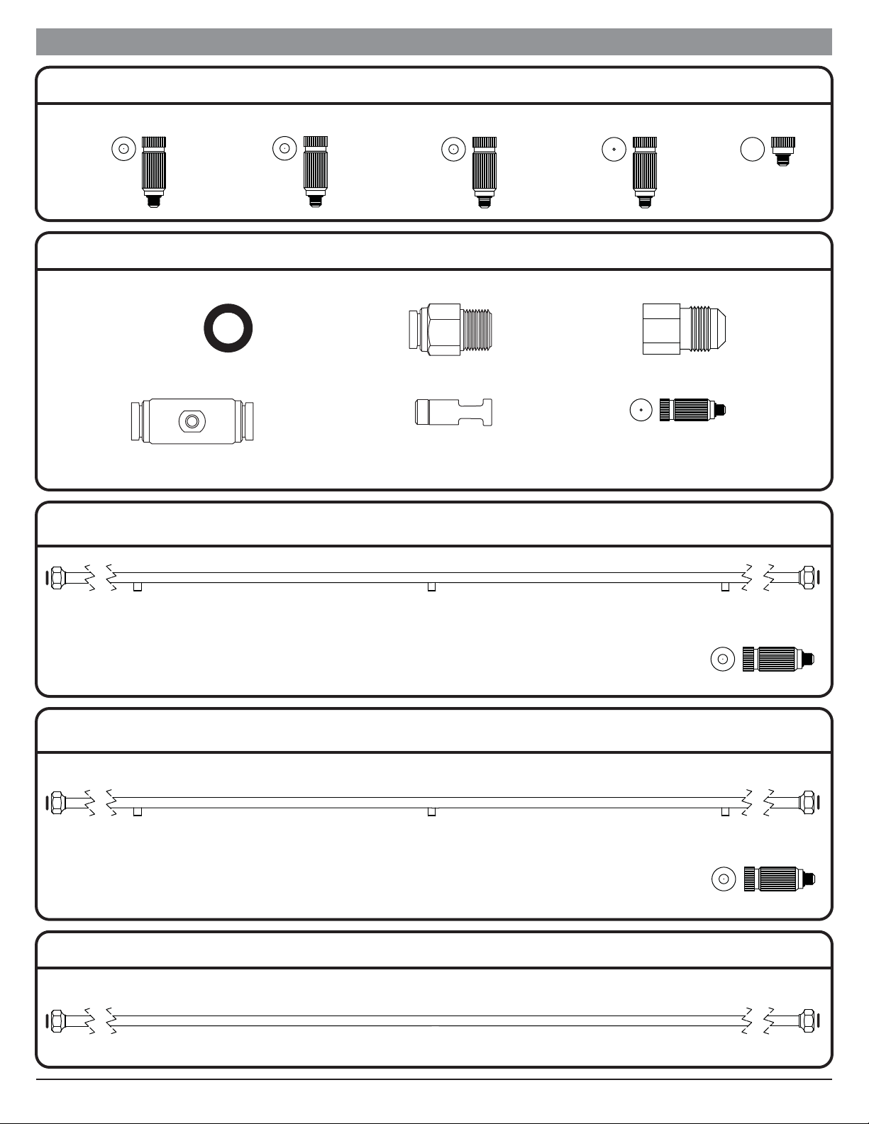
3/8” Slip Lock Connectors Compatible with
VHPR122 High Pressure Nylon Tube
1/2” Flare Connectors Compatible with
VHPR000, VHPR002, VHPR003 Stainless Steel Lines
VHPR120 - O-Ring
7/16” ID x
11/16” OD
VHPR123 - Adapter
3/8”
Slip Lock
3/8”
MIPT
VHPR134 - Elbow
3/8”
Slip Lock
3/8”
Slip Lock
VHPR154 - Splice
3/8”
Slip Lock
3/8”
Slip Lock
VIEC1000B - Tee
3/8”
Slip Lock
3/8”
Slip Lock
3/8”
Slip Lock
VIEC1000C - Tee
3/8”
Slip Lock
3/8”
Slip Lock
Nozzle
Port
VIEC1000G - Plug
Plug 3/8”
Slip Lock
1/2”
Flare
1/2”
Flare
1/2”
Flare
VHPR108 - Tee
VHPR125 - Coupling
3/8”
FIPT
1/2”
Flare
VHPR126 - Coupling
3/8”
FIPT
3/8”
FIPT
VHPR127 - Elbow
3/8”
FIPT
3/8”
FIPT
1/2”
Flare
1/2”
Flare
VHPR128 - Union
3/8”
MIPT
1/2”
Flare
VHPR129 - Union
1/2”
Flare
Plug
VHPR131 - Plug
VHPR124 - Coupler
1/2”
Female
Flare
Swivel
Nut
1/2”
Female
Flare
Swivel
Nut
3/8”
FIPT
3/8”
FIPT
VHPR122 - Tube 3/8” H.P. NylonVHPR163 - 2000 psi Ball Valve
NOTE: Spacing and quantity of nozzles is dependent on model purchased.
NOTE: Spacing and quantity of nozzles is dependent on model purchased.
VHPR123 - Adapter
3/8”
Slip Lock
3/8”
MIPT
VIEC1000C - Tee
3/8”
Slip Lock
3/8”
Slip Lock
Nozzle
Port
VIEC1000G - Plug
Plug 3/8”
Slip Lock
VHPR120 - O-Ring
7/16” ID x
11/16” OD
VHPR125 - Coupling
3/8”
FIPT
1/2”
Flare
VIEC1000I - Nozzle
Auto Drain
Valve Nozzle
VHPR2002 Series - 20’ Long SS Lines with 0.02 GPM Nozzles
VHPR2003 Series - 20’ Long SS Lines with 0.03 GPM Nozzles
VHPR2000 - 20’ Long SS Line (No Nozzles or Nozzle Ports)
VHPR162 - Auto Drain Kit
VHPR110 - Nozzle
0.02 GPM
Anti Drip
Nozzle
2
VHPR111 - Nozzle
0.03 GPM
Anti Drip
Nozzle
3
Nozzles
VIEC1000I - Nozzle
Auto Drain
Valve Nozzle
VHPR110 - Nozzle
0.02 GPM
Anti Drip
Nozzle
2
VHPR111 - Nozzle
0.03 GPM
Anti Drip
Nozzle
3
VHPR106 - Nozzle
0.05 GPM
Anti Drip
Nozzle
5
VHPR107 - Nozzle
Nozzle
Plug
IS275-17L J&D Manufacturing • 6200 Hwy 12 • Eau Claire, WI 54701 • 1-800-998-2398 • www.jdmfg.com Section D - Page 6/8
Section DParts IdentificationSection D

IS275-17L J&D Manufacturing • 6200 Hwy 12 • Eau Claire, WI 54701 • 1-800-998-2398 • www.jdmfg.com Section D - Page 7/8
Section DParts IdentificationSection D
SS3012
30” Stainless steel
panel fan ring kit
with hose connector
and (12) 0.02 GPM
Nozzles
VHPR121
3/4” ID
Cable Clamp for
Tube and Pipe
VHPR160
18”
Mounting Rod
with Hardware
to use with
VHPR159
Mounting Clip
(6)
Cable Ties
SS3012 - 30” High Pressure
Fog Ring Kit with X-Frame
Pipe / Tube Mounting
VHPR110 - Nozzle
0.02 GPM
Anti Drip
Nozzle
2
VHPR159
(10)
Black Poly
Mounting
Clip for
1/2” OD
HPF Line
VIEC1000M
3/8”
Slip Lock
1/4”
Flare
Hanging Pegs
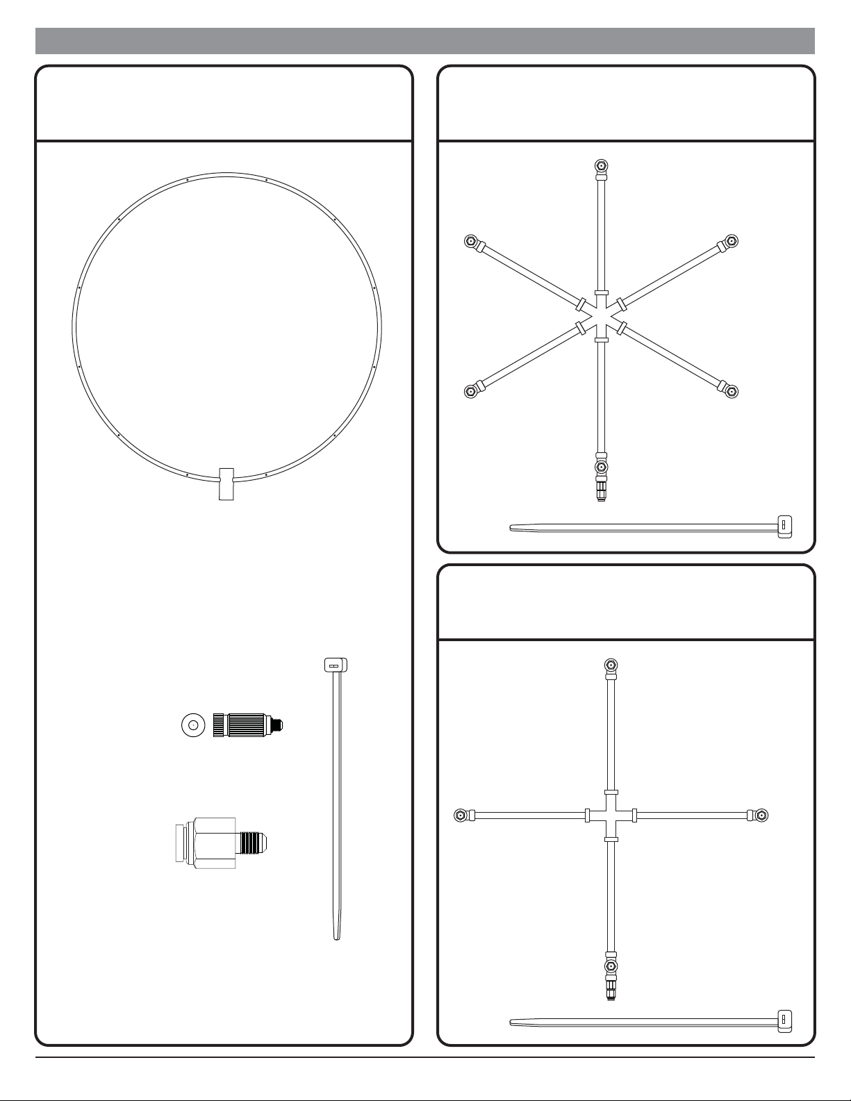
SS3011
30” Stainless steel
panel fan ring kit
with hose connector
and (12) 0.02 GPM
Nozzles
SS36SH6
13” Stainless steel
fogging cross with
hose connector and
(6) 0.008 nozzles
SS36SH
13” Stainless steel
fogging cross with
hose connector and
(4) 0.008 nozzles
(6)
Cable Ties
(4)
Cable Ties
(6)
Cable Ties
SS3011 - 30” High Pressure
Fog Ring Kit
SS36SH6 - 13” 6 Way
High Pressure Fog Cross
SS36SH - 13” 4 Way
High Pressure Fog Cross
VHPR110 - Nozzle
0.02 GPM
Anti Drip
Nozzle
2
VIEC1000M
3/8”
Slip Lock
1/4”
Flare
IS275-17L J&D Manufacturing • 6200 Hwy 12 • Eau Claire, WI 54701 • 1-800-998-2398 • www.jdmfg.com Section D - Page 8/8
Section DParts IdentificationSection D
IS275-17L J&D Manufacturing • 6200 Hwy 12 • Eau Claire, WI 54701 • 1-800-998-2398 • www.jdmfg.com Section E - Page 1/2
Section E
Guidelines for Assembling ComponentsSection E
PVC Gluing Guidelines
PTFE
Tape
3/8”
MIPT
1/2”
Flare
3/8”
MIPT
1/2”
Flare
PTFE
Tape
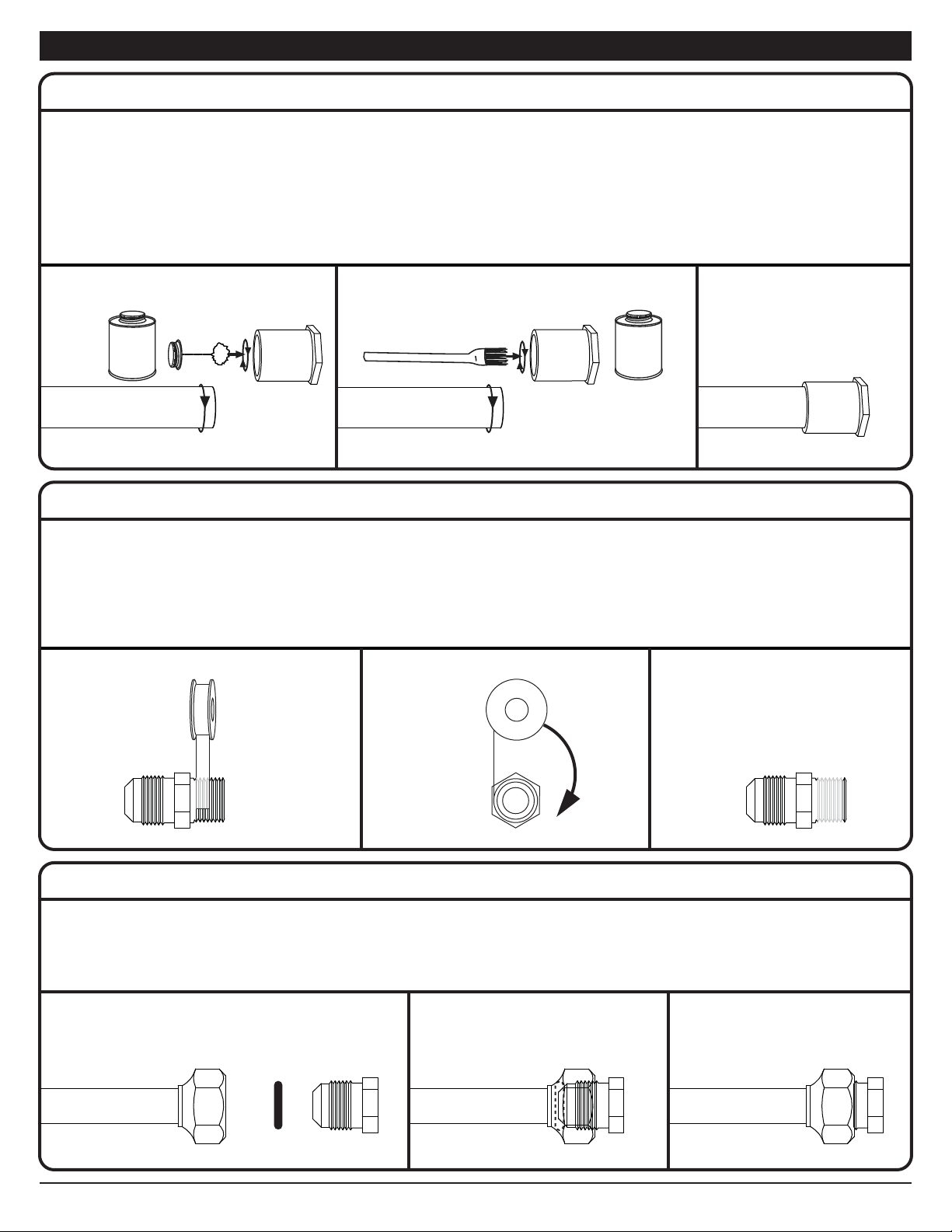
Wipe primer around the pipe end and into the fitting to prepare it for the glue/cement. Let it dry about 10 seconds. Spread an even layer of glue/cement on the
same surfaces. To keep excess glue/cement from being pushed into water piping, don't apply too much to the inside of the socket on the fitting. At this point
you have to work fast to complete the assembly. Align the fitting and pipe about a quarter turn from their final orientation. Then twist the fitting a quarter turn
as you press it onto the pipe. Twisting the fitting helps spread the glue/cement evenly to ensure a solid joint. Hold the pipe and fitting together for about 30
seconds until the cement grabs. If you let go to soon, the pipe may push out of the fitting, resulting in a weak joint.
NOTE: PVC primer and PVC glue/cement are not included. When purchasing make sure both are for use with PVC.
Read the PVC primer and PVC glue/cement manufacturer’s directions and warnings before using and apply all safety recommendations.
PVC
Primer / Cleaner
PVC
Cement / Glue
PTFE Tape & Tightening Guidelines
Hold the fitting and starting at the inner end of the threads, wrap PTFE tape tightly and evenly clockwise and upwards in a helical fashion until all but the end
thread is covered. Leaving the end thread bare makes it easier to get the thread started during assembling of joints. Continue to wind the thread clockwise and
downwards back to where you started then once more towards end of fitting. This method will provide industry standard of three layers of PTFE tape.
Screw the male thread into the female union by hand until tight, then using a wrench rotate the fitting an additional 1-2 turns, DO NOT OVER TIGHTEN.
NOTE: Some fittings may come with a layer of dried white PTFE sealant that was previously applied to the threads by the manufacturer of the connector.
DO NOT add additional PTFE tape to these fittings; just assemble as is.
1/2” Flare Connector with Required O-Ring Guidelines
1/2” flare connector ends require an o-ring to complete the union. Insert the o-ring into the union and position it so it does not block the waterway. With o-ring
in place screw the male thread into the female union by hand until tight; using a wrench rotate the fitting an additional 1/2 to 1 turn. DO NOT OVER TIGHTEN.
NOTE: Stainless steel line ends have a 1/2” flare nut on each end and include the required o-rings needed for this connection. The purchase of additional
o-rings (VHPR120) is only required for replacement if needed or when the 1/2” male flare connector is used with other 1/2” female flare connectors.
1/2”
Male Flare
1/2”
Female Flare
VHPR120
O-Ring
IS275-17L J&D Manufacturing • 6200 Hwy 12 • Eau Claire, WI 54701 • 1-800-998-2398 • www.jdmfg.com Section E - Page 2/2
Section EGuidelines for Assembling ComponentsSection E
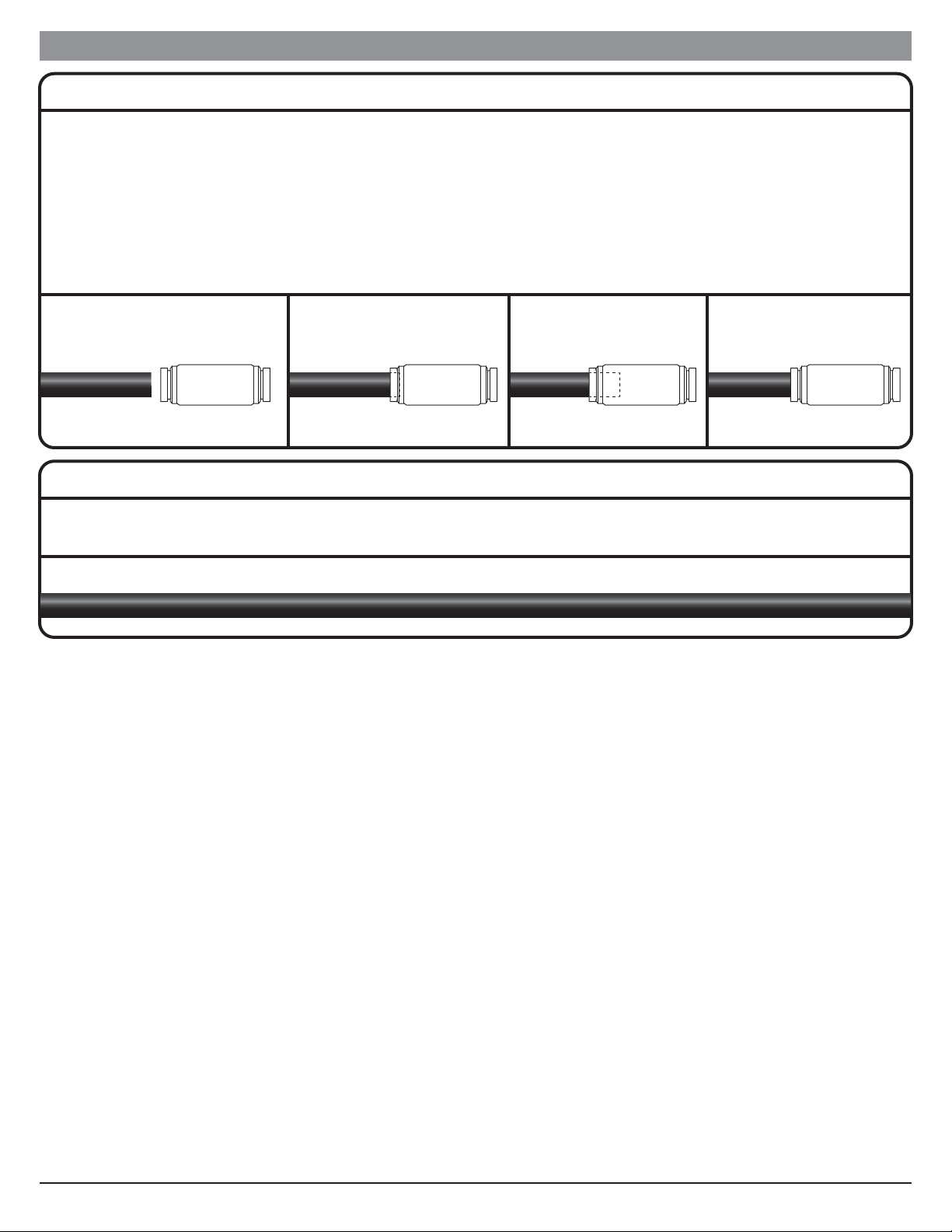
Slip Lock Guidelines
Slip lock connectors requires the nylon tube be cut straight, cleanly, and without crimping or deforming the tube while cutting.
If the other end of the fitting is not a slip lock, connect that first.
Insert the end of the nylon tube into the slip lock until you meet some resistance then push it in another 1/2” or so until it stops.
If you need to remove the nylon tube from the slip lock, the system must be depressurized. Then push the metal slip lock collar back into the fitting and pull the
nylon tube out.
NOTE: Once the nylon tube has been fully inserted into a slip lock and is removed, even for a short time, 1” of nylon tube (the amount that was inserted into
the slip lock) must be trimmed off or it will not seal properly. Keep this in mind if you intend to disassemble your system seasonally as you will want
to provide additional tubing to those sections to allow for yearly trimming until you are required to replace your nylon tubing.
3/8”
Slip Lock
3/8” High Pressure
Nylon Tube
High Pressure Nylon Tube Guidelines
When system is running the high pressure nylon tube will vibrate and jump causing nearby sharp or abrasive surfaces to cut or wear a hole in the nylon tube.
Rubber grommets, pieces of rubber mats, etc., should be used to protect the tube.
3/8” High Pressure Nylon Tube
Preparing 1” PVC Tubing 2’ Stick (VHPR151) for Assembly
Measure and mark the tube into (6) 4” sections.
Using the marks just made and a fine toothed saw cut tubing into sections.
Clean and deburr each end of cut tube.
Before Filter Tee Assembly
Following the PVC Gluing Guidelines in Section E, prime and glue a section of 4” tube, tee (SSOT), and another section of 4” tube as shown below.
After Filter Tee Assembly
Following the PVC Gluing Guidelines in Section E, prime and glue a section of 4” tube, tee (SSOT), and reducer bushing (VHPR146) as shown below.
Check and Ball Valve Assembly
Following the PVC Gluing Guidelines in Section E, prime and glue check valve (SS03), a section of 4” tube, and ball valve (SS01) as shown below.
IS275-17L J&D Manufacturing • 6200 Hwy 12 • Eau Claire, WI 54701 • 1-800-998-2398 • www.jdmfg.com Section F - Page 1/6
Section F
Filter System Assembly & InstallationSection F
4”
4” 4” 4” 4” 4” 4”
4” 4” 4” 4” 4”
4”
SS01
Ball Valve
Prime & Glue Prime & Glue
SS03
Check Valve Check and Ball Valve Assembly
SSOT
Tee
VHPR146
Reducer Bushing
Prime & Glue
4”
Prime & Glue After Filter Tee Assembly
4”
Prime & Glue
4”
Prime & Glue
SSOT
Tee
Before Filter Tee Assembly
1
2
3
4
Pressure Gauge Assembly
Following the PTFE Tape & Tightening Guidelines in Section E, tape and assemble both pressure gauges (VHPR149) to a reducer (SS19) as shown below.
SS19
Reducer
VHPR149
Pressure Gauge
PTFE
Tape Pressure Gauge Assembly
5
Arrow on valve indicates
water flow direction

2-1/2” Filter Cap Assembly
Remove the caps from each of the filter housings (VHPR135).
Following the PTFE Tape & Tightening Guidelines in Section E, tape and assemble two threaded adapters (PP10461) to each filter housing cap as shown below.
Set all three caps on a flat surface and arrange caps so IN and OUT are as shown below.
Following the PVC Gluing Guidelines in Section E, prime and glue a section of 4” tube between each cap as shown below.
IS275-17L J&D Manufacturing • 6200 Hwy 12 • Eau Claire, WI 54701 • 1-800-998-2398 • www.jdmfg.com Section F - Page 2/6
Section FFilter System Assembly & InstallationSection F
IN OUT IN OUT IN OUT
4”
Prime & Glue Prime & Glue Prime & Glue Prime & Glue
4”
2-1/2” Filter Cap Assembly
PP10461
Adapter
PTFE
Tape
PTFE
Tape
PP10461
Adapter
Cap Only - VHPR135
2-1/2” Filter Housing
6
If your filter system uses 4-1/2” filter housings, proceed to Step 8.
Attaching Brackets to 2-1/2” Filter Cap Assembly
Using either a #3 phillips head hand driven screwdriver or a #3 phillips head drill bit and drill with its clutch/torque adjusted to not strip the holes, secure the three
filter mounting brackets (VHPR142) to the filter cap assembly using (4) #14–10 x 3/4” phillips pan head screws per bracket as shown below.
7

If your filter system uses 2-1/2” filter housings, proceed to Step 10.
IS275-17L J&D Manufacturing • 6200 Hwy 12 • Eau Claire, WI 54701 • 1-800-998-2398 • www.jdmfg.com Section F - Page 3/6
Section FFilter System Assembly & InstallationSection F
4-1/2” Filter Cap Assembly
Remove the caps from each of the filter housings (VHPR139).
Following the PTFE Tape & Tightening Guidelines in Section E, tape and assemble two threaded adapters (VHPR143) to each filter housing cap as shown below.
Set all three caps on a flat surface and arrange caps so IN and OUT are as shown below.
Following the PVC Gluing Guidelines in Section E, prime and glue a section of 4” tube between each cap as shown below.
PTFE
Tape
PTFE
Tape
VHPR143
Adapter
VHPR143
Adapter
4”
Prime & Glue Prime & Glue Prime & Glue Prime & Glue
4”
IN OUT IN OUT IN OUT
4-1/2” Filter Cap Assembly
8
Attaching Brackets to 4-1/2” Filter Cap Assembly
Using either a #3 phillips head hand driven screwdriver or a #3 phillips head drill bit and drill with its clutch/torque adjusted to not strip the holes, secure the three
filter mounting brackets (VHPR153) to the filter cap assembly using (4) #14–10 x 3/4” phillips pan head screws per bracket as shown below.
9

From this point in the instructions only the 4-1/2” filter assembly will be shown in the illustrations however the same
steps must be applied to the 2-1/2” filter system as the remaining instructions are the same.
IS275-17L J&D Manufacturing • 6200 Hwy 12 • Eau Claire, WI 54701 • 1-800-998-2398 • www.jdmfg.com Section F - Page 4/6
Section FFilter System Assembly & InstallationSection F
Mounting Filter Cap Assembly
To provide the space needed to access and service the filters once system is installed, measure and mark 37” from the floor as shown below. Align the top of the
filter mounting plates to this mark and prepare the (4) locations per bracket indicated below for the installation hardware (not included). Secure the mounting
plate to your chosen location.
NOTE: Mounting location and installation hardware (not included) must be able to withstand the weight of 90lbs, the assembled unit when in use and full
of water.
Mounting
Holes
10
37”
FloorFloor Floor

Assembling Tees to Mounted Filter Assembly
Following the PVC Gluing Guidelines in Section E, prime and glue the Before Filter Tee Assembly from Step 2 to the IN side of the Filter Cap Assembly and
the After Filter Tee Assembly from Step 3 to the OUT side of the Filter Cap Assembly as shown below.
Assembling Gauges to Tees
Following the PVC Gluing Guidelines in Section E, prime and glue one of the Pressure Gauge Assemblies from Step 5 to the Before Filter Tee Assembly and
the other Pressure Gauge Assembly from Step 5 to the After Filter Tee Assembly as shown below.
Install pressure gauge so
it can be easily viewed.
Install pressure gauge so
it can be easily viewed.
Pressure
Gauge
Assembly
Pressure
Gauge
Assembly
Prime & Glue Prime & Glue
Tee must
point up
Tee must
point up
Prime & Glue Prime & Glue
After Filter
Tee Assembly
Before Filter
Tee Assembly
Filter Cap Assembly
11
12
IS275-17L J&D Manufacturing • 6200 Hwy 12 • Eau Claire, WI 54701 • 1-800-998-2398 • www.jdmfg.com Section F - Page 5/6
Section FFilter System Assembly & InstallationSection F
Assembling Check & Ball Valve to Mounted Filter Assembly
Following the PVC Gluing Guidelines in Section E,prime and glue the Check & Ball Valve Assembly from Step 4 to the Before Filter Tee Assembly as shown
below.
Install ball valve with the lever away from the
wall so lever can be turned without interference.
Prime & Glue
Check & Ball Valve Assembly
13
Assembling Adapter to Mounted Filter Assembly
Following the PTFE Tape & Tightening Guidelines in Section E, tape and assemble male adapter (VHPR147) to Before Filter Tee Assembly as shown below.
14
Attaching Labels to Bracket of Mounted Filter Assembly
Attach the labels that indicate filtration size to the mounting brackets as shown below, this will aid in filter maintenance and replacement in the future.
15
Connecting Water Source to Mounted Filter Assembly
With water shut off and following the PVC Gluing Guidelines in Section E, connect the water source to the check valve.
16
PTFE
Tape
VHPR147
Male Adapter
Connect water
source here
20
MICRON
REPLACEMENT
FILTER
5
MICRON
REPLACEMENT
FILTER
1
MICRON
REPLACEMENT
FILTER
20
MICRON
5
MICRON
1
MICRON
20
MICRON
REPLACEMENT
FILTER
5
MICRON
REPLACEMENT
FILTER
1
MICRON
REPLACEMENT
FILTER
IS275-17L J&D Manufacturing • 6200 Hwy 12 • Eau Claire, WI 54701 • 1-800-998-2398 • www.jdmfg.com Section F - Page 6/6
Section FFilter System Assembly & InstallationSection F

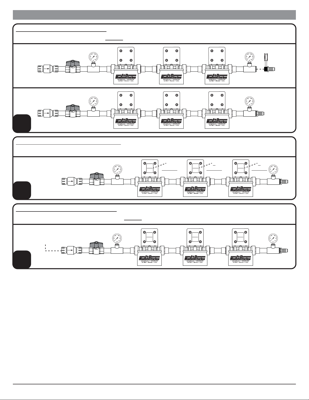
IS275-17L J&D Manufacturing • 6200 Hwy 12 • Eau Claire, WI 54701 • 1-800-998-2398 • www.jdmfg.com Section G - Page 1/3
Section G
Motor & Pump Shelf Assembly & InstallationSection G
If your structure has studs 24” on center, proceed to Step 4.
Mounting Shelf Assembly to Structure that has Studs 16” On Center
Prepare the (8) locations indicated below for the installation hardware (not included) and secure the mounting shelf to your chosen location as shown below.
NOTE: Mounting location and installation hardware (not included) must be able to withstand the weight of 145 lbs, the assembled shelf with motor and
pump assembly.
1
Assemble Shelf Support Brackets
Using a 9/16” wrench and 9/16” socket and socket wrench assemble (2) shelf braces so the mounting tabs are behind the shelf lip and secure with (2) 3/8”-16 x
1” Hex Bolts and (2) 3/8”-16 Nylock Nuts as shown below.
2
Table of contents


