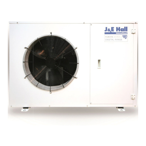
J&E Hall JEHR-0050-B1-M-1 User manual

Issue: 01.05.2019
Page 1
Contents
COMMERCIAL CONDENSING UNITS
INSTALLATION
MANUAL
V3 FUSION
FUSION SCROLL
Commercial Condensing Units
Medium Low Temperature Applications
ISSUE: 01.05.2019
V
3

Issue: 01.05.2019 Page 2
Contents
Contents & Nomenclature
2
Specifications
3
Health & Safety
4
Installation
4-7
Commissioning
7-12
Wiring iagrams 13-20
Service & Maintenance 21-22
F-Gas Information 23
Nomenclature
JEH R 0140 B 2 M 1
① ② ③ ④ ⑤ ⑥
⑦
⑧
① J & E Hall International ⑤ Unit Series
② R: Reciprocating S: Scroll ⑥ M: Medium Temperature L: Low Temperature
③ Approximate HP (0140 = 1.4hp) ⑦ Power Supply: 1: 230V / 1Ph / 50Hz 3: 400V / 3Ph / 50Hz
④ Unit Generation ⑧ EVI: Vapour Injection Unit

Issue: 01.05.2019 Page 3
Specifications
Sw ept
Volume
Oil
Charge NC
a
MCC
b
LRC
c
FLC Liquid Suction
Unit
(W D H)
Mounting
(W D)
(m³/h) (Litres) (Litres) (A) (A) (A) (A) (Litres) (Litres) (m³/h) (inch) (inch) (mm) (mm) (kgs) dB(A)
JEHR-0050-B1-M-1 n/c 1.72 1.59 1.77 1.66 1.66 1.67 AE4460Z-FZ1C 1.80 0.28 - 3.4 5.9 19.4 1 0.2 0.44 2.4 1250 1/4 3/8 49 28
JEHR-0067-B1-M-1 n/c 1.84 1.62 1.76 1.64 1.64 1.67 CAJ9480Z 2.64 0.48 - 3.1 6.7 24.1 1 0.2 0.44 2.4 1250 3/8 1/2 56 28
JEHR-0100-B1-M-1 n/c 1.79 1.66 1.77 1.64 1.64 1.68 CAJ9510Z 3.18 0.48 - 3.9 8.4 29.5 1 0.2 0.44 2.4 1250 3/8 1/2 57 28
JEHR-0113-B1-M-1 n/c 1.82 1.78 1.85 1.71 1.71 1.73 CAJ9513Z 4.21 0.48 - 4.9 11.3 33.5 1 0.2 0.44 2.4 1250 3/8 1/2 58 28
JEHR-0140-B2-M-1 n/c 2.06 1.74 1.93 2.09 2.09 1.92 CAJ4517Z 4.52 0.48 - 5.3 12.7 38.5 1 0.6 0.51 4.5 2700 3/8 1/2 67 34
JEHR-0140-B2-M-3 n/c 1.99 1.66 1.85 2.00 2.00 1.83 TAJ4517Z 4.52 0.48 - 2.3 4.0 18.0 1 0.6 0.51 4.5 2700 3/8 1/2 67 34
JEHR-0150-B2-M-1 1.61 1.88 1.80 1.80 1.97 1.97 1.93 MTZ18-5VM 5.26 0.95 - 6.5 10.0 40.0 1 0.6 0.51 4.5 2700 3/8 5/8 68 37
JEHR-0150-B2-M-3 1.77 1.91 1.86 1.86 1.95 1.95 1.87 MTZ18-4VM 5.26 0.95 - 2.6 5.0 20.0 1 0.6 0.51 4.5 2700 3/8 5/8 68 37
JEHS-0200-B2-M-1 1.92 2.40 2.18 1.92 2.02 2.02 n/c ZB15KQE-PFJ 5.90 1.30 - 7.3 18.5 58.0 1 0.6 0.51 4.5 2700 3/8 3/4 70 33
JEHS-0200-B2-M-3 2.19 2.19 2.12 1.88 2.02 2.02 n/c ZB15KQE-TFD 5.90 1.30 - 2.9 7.0 26.0 1 0.6 0.51 4.5 2700 3/8 3/4 70 33
JEHS-0250-B2-M-1 n/a 2.14 2.06 1.83 1.93 1.93 n/c ZB19KQE-PFJ 6.80 1.30 - 9.3 20.5 61.0 1 0.6 0.51 4.5 2700 3/8 3/4 72 34
JEHS-0250-B2-M-3 n/a 2.21 1.99 1.83 1.93 1.93 n/c ZB19KQE-TFD 6.80 1.30 - 4.2 7.0 32.0 1 0.6 0.51 4.5 2700 3/8 3/4 72 34
JEHS-0300-B2-M-1 n/a (2.69) n/a 1.74 1.85 1.85 n/c ZB21KQE-PFJ 8.60 1.45 - 12.2 21.5 82.0 1 0.6 0.51 4.5 2700 3/8 3/4 74 36
JEHS-0300-B2-M-3 n/a (3.10) 1.92 1.69 1.85 1.85 n/c ZB21KQE-TFD 8.60 1.45 - 4.4 10.3 40.0 1 0.6 0.51 4.5 2700 3/8 3/4 74 36
JEHS-0350-B3-M-1 2.13 (3.19) (3.43) (3.16) (3.02) (3.02) n/c ZB26KQE-PFJ 9.90 1.50 - 13.9 25.0 97.0 1 0.9 4.42 7.6 4250 1/2 3/4 112 37
JEHS-0350-B3-M-3 2.36 (3.62) (3.48) (3.22) (3.02) (3.02) n/c ZB26KQE-TFD 9.90 1.50 - 5.9 9.0 46.0 1 0.9 4.42 7.6 4250 1/2 3/4 112 37
JEHS-0400-B3-M-1 n/a (3.38) (3.61) (3.54) (3.13) (3.13) n/c ZB29KQE-PFJ 11.40 1.36 - 16.1 28.0 114.0 1 0.9 4.42 7.6 4250 1/2 7/8 119 37
JEHS-0400-B3-M-3 2.36 (3.50) (3.79) (3.49) (3.13) (3.13) n/c ZB29KQE-TFD 11.40 1.36 - 7.3 11.0 50.0 1 0.9 4.42 7.6 4250 1/2 7/8 119 37
JEHS-0500-B3-M-3 n/a (3.23) (3.21) (3.07) (2.97) (2.97) n/c ZB38KQE-TFD 14.40 2.07 - 8.2 13.5 65.5 1 0.9 4.42 7.6 4250 1/2 7/8 123 38
JEHS-0600-B3-M-3 n/a (3.23) (3.19) (3.12) (3.22) (3.22) n/c ZB45KQE-TFD 17.10 1.89 - 8.7 14.2 74.0 1 0.9 6.89 7.6 4100 1/2 1 1/8 125 40
JEHS-0680-B3-M-3 n/a (3.19) (2.96) n/a (2.96) (2.96) n/c ZB48KQE-TFD 18.80 1.80 - 11.4 19.1 101.0 1 0.9 6.89 7.6 4100 1/2 1 1/8 126 40
JEHS-0800-B4-M-3 (3.10) (3.49) (3.12) (2.95) (2.88) (2.88) n/c ZB57KCE-TFD 21.40 1.89 - 9.6 21.3 102.0 2 1.8 8.73 13.6 8500 3/4 1 1/8 204 43
JEHS-1000-B4-M-3 (3.37) (3.30) n/a n/a (2.83) (2.83) n/c ZB76KCE-TFD 29.10 3.20 - 14.4 28.0 118.0 2 1.8 8.73 13.6 8500 3/4 1 3/8 226 43
JEHR-0115-B1-L-1 n/c 1.10 n/c n/c n/a n/a 1.05 CAJ2446Z 4.55 0.48 - 2.8 8.2 30.0 1 0.2 0.44 2.4 1250 3/8 1/2 59 27
JEHR-0135-B1-L-1 n/c 1.04 n/c n/c n/a n/a 0.98 CAJ2464Z 6.00 0.48 - 4.6 10.0 40.0 1 0.2 0.44 2.4 1250 3/8 1/2 61 27
JEHR-0175-B2-L-1 n/c 1.00 n/c n/c n/c n/c 1.07 NTZ048-5VM (B) 8.40 0.95 0.50 4.5 11.0 37.0 1 0.6 0.51 4.5 2700 3/8 5/8 73 37
JEHR-0175-B2-L-3 n/c 1.11 n/c n/c n/c n/c 1.12 NTZ048-4VM (B) 8.40 0.95 0.50 2.1 4.8 16.0 1 0.6 0.51 4.5 2700 3/8 5/8 72 37
JEHR-0225-B2-L-1 n/c 1.04 n/c n/c n/c n/c 0.98 NTZ068-5VM (B) 11.80 0.95 0.50 9.2 17.0 53.0 1 0.6 0.51 4.5 2700 3/8 5/8 75 40
JEHR-0225-B2-L-3 n/c 1.11 n/c n/c n/c n/c 1.12 NTZ068-4VM (B) 11.80 0.95 0.5 3.5 8.4 25.0 1 0.6 0.51 4.5 2700 3/8 5/8 74 40
JEHS-0200-B2-L-3 n/c 0.97 n/a n/a n/a n/a n/c ZF06KQE-TFD 5.90 1.30 0.50 2.7 6.0 26.0 1 0.6 0.51 4.5 2700 3/8 3/4 76 32
JEHS-0300-B2-L-3 n/c 1.09 n/a n/a 0.97 0.97 n/c ZF09KQE-TFD 8.00 1.50 0.50 3.8 6.5 40.0 1 0.6 0.51 4.5 2700 3/8 3/4 78 33
JEHS-0400-B3-L-3 n/c (1.88) (1.67) (1.65) (1.67) (1.67) n/c ZF13KQE-TFD 11.80 1.90 0.60 4.9 10.0 51.5 1 0.9 4.42 7.6 4250 1/2 7/8 132 37
JEHS-0500-B3-L-3 n/c (1.79) (1.67) (1.64) n/a n/a n/c ZF15KQE-TFD 14.50 1.90 0.60 6.7 12.0 64.0 1 0.9 4.42 7.6 4250 1/2 7/8 132 39
JEHS-0600-B3-L-3 n/c (1.80) (1.64) n/a (1.64) (1.64) n/c ZF18KQE-TFD 17.10 1.90 0.60 7.6 12.5 74.0 1 0.9 4.42 7.6 4250 1/2 7/8 133 41
JEHS-0750-B4-L-3 n/c (1.82) n/a n/a (1.64) (1.64) n/c ZF25K5E-TFD 21.40 1.90 0.60 6.9 16.6 102.0 2 1.2 4.14 13.6 5750 1/2 1 1/8 203 41
JEHS-0950-B4-L-3 EVI n/c (1.79) (1.76) (1.63) (1.76) (1.76) n/c ZF18KVE-TFD 17.10 1.90 0.60 7.3 13.0 74.0 2 1.2 8.73 13.6 5870 1/2 7/8 200 37
JEHS-1150-B4-L-3 EVI n/c (1.78) (1.68) (1.78) (1.71) (1.71) n/c ZFI36KQE-TFD 21.40 1.90 0.60 8.9 20.5 102.0 2 1.8 8.73 13.6 8500 1/2 1 1/8 211 42
Low Temperature
4
C
1348 612 1727 940 560
3 1353 575 872 945 500
2 1101 444 662 703 408
2D1101 444 662 703 408
876 420 607 545 400
1101 444 662 703 408
1353 575 872 945 500
R404A
R407A
R407F
R448A
Unit Dry
Weight
Dimensions
No.
Electrical Data
Coil
Volume
Liquid
Receiver Airflow
Fan Motors
Compressor Connections
Oil
Type
Type
R452A
3
Unit Model
Series
COP / (SEPR) Compressor
Oil Sep.
Charge
1
A
2
R449A
R134a
SPL @
10m
d
Medium Temperature
940 560
1A876 420 607 545 400
4
C
1348 612 1727
2 1101 444 662 703 408
B
COP/SEPR according to Ecodesign conditions. n/c = not compatible w ith this refrigerant n/a = compatible w ith this refrigerant but no data available at Ecodesign condition or does not meet Ecodesign requirement
a
NC = Nominal Current @ condition -10
°
Cte / +32°Cta MT and -35°Cte / +32°Cta LT w ith R404A refrigerant
b
MCC = Ma imum Continuous Current
Oil Type D = Maneurop Ester 175PZ (New 'B' range NTZ compressors)
Oil Type A = Uniqema Emkarate RL32CF / Oil Type B = Maneurop Ester 160PZ / Oil Type C = Polyolester Oil - (Copeland Ultra 22 CC, Copeland Ultra 32 CC, Copeland Ultra 32-3MAF, Mobil EAL Arctic 22CC, Uniqema Emkarate RL32CF)
c
LRC = Locked Rotor Current
d
Sound Pressure Level measured in an anechoic room (-10/+32°C) MT & (-25/+32°C) LT conditions. Alternative conditions may produce dif ferent results

Issue: 01.05.2019 Page 4
Health and Safety
Before Installation
• Ensure the units received are the correct models for the
intended application.
• Ensure the refrigerant, voltage and MWP are all suitable for
the proposed application.
• Check there is no damage to the units. Any damage should be
advised to the supplier immediately.
• Check that the proposed equipment locations are suitable
and provide adequate support for the weight of the units.
During Installation and subsequent maintenance
• Installation and maintenance are to be performed only by
qualified personnel who are familiar with local codes and
regulations, and experienced with this type of equipment.
• If lifting equipment is required, ensure that it is suitable for
purpose, certificated and that the operatives are qualified to
use it.
• Safe working methods are identified and operatives have
suitable Personal Protective Equipment (PPE).
• Ensure the working area has adequate ventilation during
brazing procedures.
• The units contain moving machinery and electrical power
hazards, which may cause severe injury or death. isconnect
and shut off power before installation or service of the
equipment.
• Refrigerant release into the atmosphere is illegal. Proper
evacuation, recovery, handling and leak testing procedures
must be observed at all times.
• Units must be earthed and no maintenance work should be
attempted prior to disconnecting the electrical supply.
• The electrical covers and fan guards must remain fitted at all
times.
• Use of the units outside of the design conditions and the
application for which the units were intended may be unsafe
and be detrimental to the units, regardless of short or long-
term operation.
• The units are not designed to withstand loads or stresses from
other equipment or personnel. Such extraneous loads or stress
may cause failure/leak/injury.
Installation
Unit location
• In order to achieve maximum cooling capacity, the installation
location for the condensing unit should be carefully selected.
• Install the condensing unit in such a way so that hot air ejected
by the condensing unit cannot be drawn in again (short circuit
of hot discharge air). Allow sufficient space for maintenance
around the unit.
• Ensure that there is no obstruction to air flow into or out of
the unit. Remove obstacles which block air intake or
discharge.
• The location must be well ventilated, so the unit can draw in
and distribute plenty of air thus lowering the condensing
temperature.
• To optimize the unit running conditions, the condenser coil
must be cleaned at regular intervals.
• The unit must be level in all directions.
Installation clearances
• The installation location should allow sufficient space for air
flow and maintenance around the unit.
Im
portant Note:
Only qualified personnel, who are familiar with refrigeration
systems and components including all controls, should perform
the installation and start-up of the system. To avoid potential
injury, use care when working around coil surfaces or sharp edges
of metal cabinets. All piping and electrical wiring should be
installed in accordance with all applicable codes, ordinances and
local by-laws.
X
X

Issue: 01.05.2019 Page 5
Installation
Field piping
To ensure satisfactory operation and performance, the
following points should be noted for field piping
arrangements:
• Pipework routes must be as simple and as short as possible.
• Avoid low points on pipework where oil can accumulate.
• Suction gas velocity must be sufficient to ensure good oil
return.
• Use only clean, dehydrated refrigeration grade copper tube
with long radius bends.
• Avoid flare type connections and take great care when brazing.
Use only silver alloy rods.
• Run braze without over filling to ensure there is no leakage into
the tube.
• To prevent oxidation, blow oxygen free nitrogen through
pipework when brazing.
• Install insulation on all suction lines and on all pipes
penetrating walls or passing through hot areas.
• Adequately support all pipe work at a maximum of 2 metre
intervals.
• Where the condensing unit is situated below the indoor unit
(coldroom evaporator / display case), the height difference
between the two units should be no more than 6 metres.
• In vertical pipework, the use of U-trap and double suction risers
is often required. These suction risers must always be fitted
with a U-trap at the bottom and a P-trap at the top and never
be higher than 4m unless a second U-trap system is fitted.
• Additional oil may be required if piping length exceeds 20m or
multiple oil traps are fitted. Check the oil level closely during
commissioning and add oil as necessary. Add oil in small
amounts. o not overfill the compressor!
• When installing a single compressor condensing unit with
multiple evaporators connected which operate independently,
care should be taken to ensure that the evaporating
pressure/temperature does not fall outside the compressor
operating limit at minimum load. If there is a potential for this
scenario, consider multiple evaporators fed by a single
solenoid valve or separate condensing units.
• Suction pipework should slope gently back towards the unit to
assist oil return to the compressor. A fall of approximately 2cm
per metre of pipework is acceptable.
• Liquid lines should be sized to ensure a full supply of liquid
refrigerant to the expansion device. Careful attention should
be paid to sizing of liquid lines on large risers (maximum 6m).
• In some circumstances, a suction accumulator (not supplied)
may be required. It offers protection against refrigerant flood
back during operation and also against off-cycle migration by
adding internal free volume to the low side of the system.
• Tests must be conducted to ensure the amount of off-cycle
migration to the compressor does not exceed the compressor’s
charge limit.
• Wherever possible the system should be installed to utilize a
pump down configuration.
• An MOP expansion valve is recommended for all Low
Temperature installations.
• Maximum recommended pipe length is 25m for Reciprocating
units and 50m for Scroll units.
Correct line sizing will minimize the pressure drop and
maintain sufficient gas velocity for proper oil return.
ipe size selection (For EVI units only)
Sizing of liquid and suction lines for EVI model will be different
from standard scroll models. Piping sizes of this model need to
follow the recommended correction coefficient of cooling capacity.
This is vital as if the pipework selected is oversized, especially for
the suction pipe, the gas velocity will be decreased at low mass
flow rate / low evaporating temperature, causing oil return
problems. Undersized suction lines will also cause decreased
capacity due to increased pressure drop.
The correction factor of refrigerant R404A is shown as below table:
For instance,
At condition of Te -35°C, Ta +32°C
Refrigerant R404A
Published cooling capacity = 5.9kW.
Cooling capacity = Correction factor x Published cooling capacity
= 0.63 x 5.9 kW
= 3.707kW
Therefore, the pipe sizes should be selected against the corrected
capacity of 3.71kW.
Ta Te (Watts) -40 -35 -30 -25 -20
27 CF 0.64 0.66 0.68 0.70 0.72
32 CF 0.61 0.63 0.65 0.67 0.69
35 CF 0.59 0.61 0.63 0.65 0.67
38 CF 0.57 0.59 0.61 0.63 0.65
43 CF 0.54 0.55 0.57 0.58 0.60
Important Note:
Pipe sizing should only be determined by qualified personnel. All
local codes of practice must be observed in the installation of
refrigerant piping.
Important Note:
One of the main factors affecting equipment reliability and
compressor service life is refrigeration circuit contamination.
uring installation, circuit contamination can be caused by:
• Brazing & Welding Oxides
• Filings & Particles from de-burring pipework
• Brazing Flux
• Moisture & Air

Issue: 01.05.2019 Page 6
Installation
The correction factor of refrigerant R407A is shown as below table:
The correction factor of refrigerant R407F is shown as below table:
The correction factor of refrigerant R448A/R449A is shown as
below table:
Insulation selection (For EVI units only)
The liquid pipe connecting CCU service valve to the evaporator
must be well insulated with recommended wall thickness of
minimum ¾’’.
Expansion valve selection (For EVI units only)
The lower liquid temperature of the EVI units can increase
evaporator expansion valve capacities. Selection of the expansion
valve needs to be done based on the expected amount of sub-
cooling shown in below tables:
(A.) R404A
Amount of Sub-cooling (K)
Ta\Te -40 -35 -30 -25 -20
27 39.9 36.9 33.9 30.9 27.9
32 40.9 37.9 34.9 31.9 28.9
35 41.5 38.5 35.5 32.5 29.5
38 42.1 39.1 36.1 33.1 30.1
43 43.1 40.1 37.1 34.1 31.1
(B.) R407A
Amount of Sub-cooling (K)
Ta\Te -40 -35 -30 -25 -20
27 33.1 32.8 32.4 32.1 31.8
32 38.0 37.0 35.9 34.9 33.8
35 41.0 39.5 38.0 36.5 35.0
38 43.9 42.0 40.1 38.1 36.2
43 48.9 46.2 43.5 40.9 38.2
(C.) R407F
Amount of Sub-cooling (K)
Ta\Te -40 -35 -30 -25 -20
27 33.8 33.5 33.1 32.8 32.5
32 38.8 37.8 36.7 35.7 34.6
35 41.9 40.4 38.8 37.3 35.8
38 44.9 42.9 41.0 38.9 37.0
43 50.0 47.2 44.5 41.8 39.0
( .) R448A/R449A
Amount of Sub-cooling (K)
Ta\Te -40 -35 -30 -25 -20
27 33.1 32.8 32.4 32.1 31.8
32 37.9 36.9 35.8 34.8 33.8
35 40.9 39.4 37.9 36.4 34.9
38 43.8 41.9 40.0 38.0 36.1
43 48.8 46.1 43.4 40.8 38.1
ressure testing
The condensing units are pressure tested in the
factory prior to dispatch. All units come with a holding
charge of oxygen free nitrogen.
Once the pipework installation is complete, it should be pressure
tested prior to evacuation to test for leaks.
A pressure leak test should be carried out using oxygen free nitrogen
(OFN). NEVER USE OXYGEN FOR PRESSURE TESTING SYSTEMS. A
calibrated nitrogen pressure regulator must always be used. Before
starting any pressure testing, ensure the area surrounding the
system is safe, inform relevant personnel and fit warning signs
indicating high pressure testing. Also, use correct PPE as required.
Always pressurize the system slowly, preferably in stages up to the
maximum required pressure. Maximum test pressures applicable
to the unit are as follows:
Listen for any possible leaks and check all joints with bubble spray.
If any leaks are discovered, release pressure slowly from system
until empty, repair leak and then restart pressure testing procedure.
Never attempt to repair a leak on a pressurized system.
A strength test should also be incorporated (to installed pipework
only) according to local regulations.
Once testing has been completed satisfactorily, release the
pressure from the system gradually and safely to external
atmosphere.
Ta Te (Watts) -40 -35 -30 -25 -20
27 CF 0.73 0.73 0.73 0.73 0.73
32 CF 0.68 0.69 0.69 0.70 0.70
35 CF 0.65 0.66 0.67 0.67 0.68
38 CF 0.62 0.63 0.64 0.65 0.66
43 CF 0.57 0.58 0.60 0.61 0.63
Ta Te (Watts) -40 -35 -30 -25 -20
27 CF 0.72 0.73 0.73 0.73 0.72
32 CF 0.68 0.68 0.69 0.69 0.69
35 CF 0.65 0.66 0.66 0.67 0.67
38 CF 0.62 0.63 0.64 0.65 0.65
43 CF 0.57 0.58 0.60 0.61 0.62
Ta Te (Watts) -40 -35 -30 -25 -20
27 CF 0.71 0.72 0.71 0.72 0.72
32 CF 0.67 0.68 0.68 0.68 0.69
35 CF 0.65 0.65 0.65 0.66 0.67
38 CF 0.62 0.63 0.63 0.64 0.65
43 CF 0.58 0.59 0.59 0.60 0.61
Test pressure
High side Low side
28 barG
(405 psiG)
19 barG
(275 psiG)

Issue: 01.05.2019 Page 7
Installation
Evacuation & Charging
Once pressure testing has been completed, the system can now be
evacuated to remove air and any moisture from the piping. This
can be done as follows:
• Ensure any nitrogen charge is safely released from the
system.
• Connect a gauge manifold to the connections on the
service valves on the condensing unit.
• Connect a vacuum pump and vacuum gauge to the
system.
• Ensure all gauge manifold and service valves are open as
required.
• Evacuate the system until vacuum is below 250 microns
(0.25 torr).
Note: A triple evacuation procedure is recommended for all new
systems or where moisture is suspected
Once the system is isolated and the vacuum pump is switched off,
any rise in pressure indicates that either there may be a leak in the
system or moisture is still present. In this case, recheck the system
for leaks, repair as necessary, and then restart the evacuation
procedure. Once completed satisfactorily, the vacuum pump and
vacuum gauge can be removed.
At this point, the refrigerant charge can be added to the system as
required. Refrigerants must be charged in the liquid phase. Charging
of liquid into the suction side of the system should ONLY be done
with a metering device. Use calibrated weighing scales to record
the amount of refrigerant added to the system.
Electrical
Mains cable type and sizing must be selected for the
particular application and the electrical installation
should conform to the current local standards.
• Cables to the condensing unit should wherever possible
be routed through the cable glands supplied on the rear
of the units.
• Connect the mains supply to the units as per the wiring
diagrams on pages 13–20.
To gain access to the electrical box, turn the mains isolator switch
on the end of the unit to the OFF position, remove the screws from
the end cover panel and remove panel. The electrical box is located
behind the panel. Remove the screws in the electrical box cover to
access components.
Commissioning
re startup checks
Before starting the condensing unit, the following
checks should be carried out as a minimum:
• Check electrical supply is correct and all connections are
sound.
• All moving parts are free and guards fitted.
• Compressor oil level satisfactory.
• Initial settings for safety switches and fan speed control.
• Overload set correctly.
• All valves in correct operating position.
• Initial refrigerant charge.
• Crankcase heater energized for a minimum of 12 hours
before compressor start-up.
• Gauge manifold connected to both low and high sides of
system.
Running the unit
• Run the unit and check compressor and condenser fan
operation.
• Check system pressures and temperatures, gas charge
and running currents of motors to ensure correct
operation.
Important Note:
The mains electrical supply to the condensing unit must be via a
suitable motor rated circuit breaker or fuse. A mains isolator is
fitted to all condensing units therefore an additional isolator is not
required unless site conditions or regulations dictate differently.
J & E Hall Fusion condensing units require either a 230 volt / 1
phase / 50Hz supply or a 400 volt / 3 phase / 50Hz supply, both of
which must include a Neutral and an Earth. These systems are not
suitable for any other supply voltages (other than a deviation of +/-
10% of the above values) and are not suitable for 60Hz supplies.
When utilizing a three phase supply, ensure that the compressor
motor rotates in the correct direction (Fusion Scroll models only).
Please see note on page 8.
Important Note:
Moisture prevents proper functioning of the compressor and the
refrigeration system. Ensure that a good quality vacuum pump is
used to pull a minimum vacuum of 250 microns (0.25 torr).
Important Note:
There must be no more than 10 compressor starts per hour. A
higher number reduces the service life of the compressor. There
is no minimum off time for scroll compressors, as they start
unloaded. However, consideration should be given to ensuring an
adequate minimum run time to ensure proper oil return. A
minimum runtime of 3 minutes after each compressor start and a
minimum idle time of 3 minutes after each stop are
recommended. Only during the pump down cycle may the
compressor run for shorter intervals.

Issue: 01.05.2019 Page 8
Commissioning
• Check compressor suction superheat. This should be
between 10K and 20K at normal operating conditions.
• Final adjustment of safety switch settings and fan speed
control.
• Allow the system to run for 3 – 4 hours. Check compressor
oil level and top up with the correct oil type as required
(see page 3). Recheck the compressor oil level again after
24 hours operation.
• Carry out final leak test and ensure all panels/covers are
fitted and screws tightened.
• Log all information along with the system model and serial
numbers for future reference.
• Ensure that the customer / responsible person are
provided with basic operating instructions and where
electrical isolators are situated in case of emergency.
Compressor operation
Scroll compressor motors are designed to run only in one direction.
This is not an issue with single phase compressors as they will always
run in the correct direction. The correct rotation of a three phase
compressor motor depends on the connection of the three
incoming phases to the unit. Correct rotation can be determined by
a drop in suction pressure and a rise in discharge pressure when the
compressor is energized. Running the compressor for a short period
of time in reverse direction will have no negative impact but
prolonged running in reverse direction may cause premature
failure. To reverse the rotation of a three phase scroll compressor,
shut off the incoming power supply to the unit, swap connection of
any two of the three incoming phases at the unit isolator, reapply
power to the unit and following compressor restart, recheck
operating pressures.
Compressor rotalock connections
The rotalock connections as used on some compressor models are
sealed with Loctite 554 thread sealant. The connections should be
leak tested at commissioning and during service/maintenance
visits. For further information including recommended torque
tightening values, please refer to Service & Maintenance section
on pages 21-22.
Vacuum operation
o not operate scroll compressors in a vacuum condition, as this
will cause the scrolls to overheat very quickly causing premature
failure.
System charge
Ensure an adequate liquid charge has been introduced to the high
side of the system before starting to ensure a minimum operating
pressure on the suction side of 0.5 bar is maintained, otherwise
overheating of the scrolls and subsequent damage may occur.
Dual ressure Switch
The pressure switches fitted to condensing units with auto reset
for low pressure and manual reset for high pressure are NOT
factory preset.
Setting rocedure for Dual ressure Switch
High ressure side
Turning the adjusting screw (8) clockwise will increase the cut-out
pressure setting. Turning the adjusting screw anti-clockwise will
decrease the cut-out pressure setting. The differential setting is
fixed so the cut-in will vary with the cut-out setting. Lock the
spindle with locking plate after setting.
Low pressure side
Range: Turning the range adjusting screw (2) clockwise will decrease
the cut-in pressure setting. Turning the range adjusting screw anti-
clockwise will increase the cut-in pressure setting.
ifferential: Turning the differential adjusting screw (3) clockwise
will increase the differential pressure setting. Turning the
differential adjusting screw anti-clockwise will decrease the
differential pressure setting.
Lock the spindle with locking plate after setting.
Safety pressure switch settings
The Saginomiya dual pressure switch fitted to all JEH model
condensing units with auto reset for low pressure and manual reset
for high pressure is NOT factory preset. BOTH THE L AND H
SWITCH SETTINGS MUST BE ADJUSTED TO SUIT THE A LICATION
BEFORE STARTING THE UNIT. Be sure that the high pressure setting
does not exceed the receiver’s maximum service pressure.

Issue: 01.05.2019 Page 9
Commissioning
High pressure safety
The high pressure safety switch is required to stop the compressor
should the discharge pressure exceed the values shown in the
following table. The high pressure switch can be set to lower values
depending on the application and ambient conditions.
Low pressure safety
The low pressure safety switch protects the compressor against
deep vacuum operation, a potential cause of failure due to internal
arcing and also operation outside the compressor limits.
The low pressure safety cut out should never be set below the
settings as shown in the following table. For systems without pump-
down the LP switch signal contact shall be used to energize a low
pressure safety alarm.
Compressor operating pressures
Compressor operating pressures should be kept within the
following limits:
Recommended compressor working pressure range
XGE Fan Speed Controller (Series 2 & 3 & 4 Units)
The fan speed controller is factory set to 19 bar for operation with
R4*** series refrigerant to ensure compressor always operates
within envelope at all declared working condition. If operate with
R134a, the fan speed controller setting need to be set to 13bar.
This can be adjusted to suit site conditions / application or
alternative refrigerants. The XGE controls are set to stop fan at
Pmin.
Recommended settings to gain higher energy efficiency as
published in the Ecodesign data sheets are as follows:
Medium Temperature
Low Temperature
Fan control Switch (Series 1 LT units only)
The high energy efficiency as shown in eco-design sheet can be
obtained with the setting shown in below table.
For model in Series 1 LT:
Discharge Thermostat
Model JEHS-0750-B4-L-3 and all EVI units are mounted with
discharge thermostat (cut off = 125⁰C, cut in = 90⁰C) to protect the
compressor. For other unit models, it is recommended to install
the discharge thermostat if operating in extreme condition (low
evaporating and high ambient temperature).
Compressor
Refrigerant
S1/S2 Max. HP Set
Compressor MTZ NTZ MTZ
Refrigerant R404A/R407A/R407F/R448A/R449A/R452A R404A/R452A R134a
S2 Max. HP Set 18 bar
Compressor ZB
Refrigerant R134a
S2/S3/S4 Max. HP Set 18 bar
27 bar
27 bar
Unit Series ZB/ZF/ZFI
R404A/R407A/R407F/R448A/R449A
AE/CAJ/TAJ
R404A/R407A/R407F/R448A/R449A/R452A
27 bar
Unit Series
Unit Series
Compressor Model CAJ/NTZ
ZF/ZFI
Unit Series 1&2 2 & 3 & 4
R404A
R404A
R404A
R404A
R407A
R407A
R448A
R407A
R407F
R407F
R449A
R407F
R448A
R448A
R452A
R448A
R449A
R449A
R449A
R452A
Application
M in. Cut Out (barG) 1 0.6 2 0.6 0.1 0.3
M in. Cut Out (psi) 15 9 30 9 2 5
R449A
R452A
1.5
22
L*
AE/CAJ/TAJ MTZ ZB
1 & 2 2 2 & 3 & 4
Refrigerant R134a R134a
M*
R404A
R407A
R407F
R448A
Compressor Model
CAJ/NTZ
ZF/ZFI
Unit Series
1&2
2 & 3 & 4
R404A
R134a
R404A
R134a
R404A
R404A
R407A
R407A
R448A
R407A
R407F
R407F
R449A
R407F
R448A
R448A
R452A
R448A
R449A
R449A
R449A
R452A
Application
* edium Temperature L* Low Temperature
0.1 ~ 3.3
13.2 ~
27.7
13.2 ~
27.7
2.0 ~
7.1
0.6 ~
3.8
0.1 ~ 3.3
13.2 ~ 27.7
1.5 ~ 8.3Low Side (barG) 1.0 ~
7.2
0.6 ~
4.7
Refrigerant
M*
R404A
R407A
R407F
R448A
R449A
R452A
L*
High Side (barG) 13.2 ~
27.7
7.9 ~
15.8
7.1 ~
27.7
6.6 ~
15.8
AE/CAJ/TAJ
MTZ
ZB
1 & 2
2
2 &3 & 4
Refrigerant R134a
Series 2 19 13
Series 3 10 13
Series 4 10 10
Setting
R404A/R407A/R407F/R448A/R449A/R452A
Refrigerant
19
13
17
R404A/R407A/R407F/R448A/R449A/R452A
JEHR odels - Series 2
JEHS odels - Series 2 & 3 & 4 (except EVI)
JEHS odels - EVI unit
Setting
Refrigerant R404A
R448A
R449A
R452A
Setting (bar)
Cut in
Setting (bar)
ifferential
* default factory setting
16*
7*
Clockwise: Increase
pressure set point
Anticlockwise: ecrease
pressure set point
360
0
= 1 turn
Approx. 1.5 bar
G

Issue: 01.05.2019 Page 10
Commissioning
Units with microchannel condenser coils
Care must be taken during charging a unit with refrigerant when a
microchannel condenser coil is fitted. Because the microchannel
coils hold less refrigerant than traditional fin/tube coils, it is easier
to overcharge, especially if the system is commissioned during
winter time when the ambient temperature is colder. If too much
refrigerant is added, this may cause tripping of the high pressure
switch in warmer weather. Always check that the amount of
condenser sub cooling is not excessive which may indicate
refrigerant overcharge.
System operation
Once the system is correctly charged with refrigerant and the
operating condition is stable, check that the compressor suction
superheat is between 10K and 20K and that the compressor
discharge temperature is between 50°C and 90°C. A suction
superheat that is too low may indicate liquid refrigerant return to
the compressor, whereas a suction superheat that is too high will
not provide enough cooling effect for the compressor and will also
cause high discharge temperatures. In either case, it is likely that
compressor damage/failure will occur.
For EVI Units Only:
Controller EXD-H 1
The controller EX -HP1 used in the Series 4 EVI units operates as an
economizer control. The setting of controller is preset by the factory
and is password protected. Users are not allowed to change any
settings in the controller.
Safety Instructions:
Electrical Installation
• o not operate system before all cable connections are
completed.
• Refer to wiring diagram for electrical connections.
• Class II category transformer is required for 24VAC power
supply
• o not connect any EX -HP1 input to main voltage as it will
permanently damage the controller.
• When connecting wires of expansion valve and pressure
sensor, consider color coding as follow:
1. EXM : BR: BROWN; BL: BLUE, OR: ORANGE; YE: YELLOW;
WH: WHITE
2. PT5 : BN: BROWN; WH: WHITE
Display/ keypad unit (LEDs and button functions)
• In standard mode the superheat is shown at the display. In
case of liquid injection and economizer function this
changes to discharge temperature.
• To display other data of EX -HP1 press “SEL” button for 1
second until index number according to below table
appears. Release “SEL” button and the next variable data
will appears. By repeating the procedure variable data can
be displayed in sequence as measured superheat (K)
Measured suction pressure (bar) valve position (%)
Measured suction gas temperature (
°C) Calculated
saturated temperature (°C) Measured discharge temperature
(°C) REPEATING
Digital input Di1/Di2
• The digital input i1 is the interface between controller
EX -HP1 and system controller if Modbus communication
has not been used.
• The digital status is dependent to operation of system’s
compressor or demand.
Variable data Controller EXD-H 1
efault Superheat, K 1 0
Suction pressure, bar
1 1
Valve position, %
1 2
Suction gas temperature, °C
1 3
Saturation temperature, °C
1 4
ischarge temperature, °C
1 5
Operating Condition Digital input status
Compressor starts Closed (Start)
Compressor stops Open (Stop)
1.
Read installation instruction carefully. Failure to
comply can result in device failure, system
damage or personal injury.
2. Only person having appropriate knowledge and
skill are allowed to manipulate the controller.
3. Disconnect all voltages from system before
installation.

Issue: 01.05.2019 Page 11
Commissioning
Manual mode operation
Warning: All alarms are disabled during manual control. We
do not recommend unattended operation of system during
manual control.
Manual alarm reset clearing functional alarms
(except hardware error)

Issue: 01.05.2019 Page 12
Commissioning
EXD – H 1 Error/ Alarm handling
Note: When multiple alarms occur, the highest priority alarm is displayed until being cleared. Then the next highest alarm is displayed until all alarms are cleared.
Only then will parameters will be shown again

Issue: 01.05.2019 Page 13
Wiring Diagrams
JEHR-0050-B1-M-1
JEHR-0067-B1-M-1, JEHR-0100-B1-M-1, JEHR-0113-B1-M-1

Issue: 01.05.2019 Page 14
Wiring Diagrams
JEHR-0115-B1-L-1, JEHR-0135-B1-L-1
JEHR-0140-B2-M-1

Issue: 01.05.2019 Page 15
Wiring Diagrams
JEHR-0140-B2-M-3
JEHR-0150-B2-M-1, JEHR-0175-B2-L-1, JEHR-0225-B2-L-1

Issue: 01.05.2019 Page 16
Wiring Diagrams
JEHR-0150-B2-M-3, JEHR-0175-B2-L-3, JEHR-0225-B2-L-3
JEHS-0200-B2-M-1, JEHS-0250-B2-M-1, JEHS-0300-B2-M-1

Issue: 01.05.2019 Page 17
Wiring Diagrams
JEHS-0200-B2-M-3, JEHS-0250-B2-M-3, JEHS-0300-B2-M-3,
JEHS-0200-B2-L-3, JEHS-0300-B2-L-3
JEHS-0350-B3-M-1, JEHS-0400-B3-M-1

Issue: 01.05.2019 Page 18
Wiring Diagrams
JEHS-0350-B3-M-3, JEHS-0400-B3-M-3, JEHS-0500-B3-M-4, JEHS-0600-B3-M-3, JEHS-0680-B3-M-4,
JEHS-0400-B3-L-3, JEHS-0500-B3-L-3, JEHS-0600-B3-L-3
JEHS-0800-B4-M-3, JEHS-1000-B4-M-3

Issue: 01.05.2019 Page 19
Wiring Diagrams
JEHS-0750-B4-L-3
JEHS-0950-B4-L-3 EVI

Issue: 01.05.2019 Page 20
Wiring Diagrams
JEHS-1150-B4-L-3 EVI
This manual suits for next models
36
Table of contents
Other J&E Hall Heat Pump manuals
Popular Heat Pump manuals by other brands
Anslut
Anslut Jula 416-086 operating instructions

ClimateMaster
ClimateMaster Tranquility TR Series Installation, operation & maintenance instructions

Nordyne
Nordyne Q5RF Series User's manual & installation instructions
SCM
SCM CUBO2 SMART Oem manual

AERMEC
AERMEC NRP 0800 installation manual
fluidra
fluidra ASTRALPOOL Viron Series Installation and operating instructions

elco
elco AEROTOP G Installation, operation and maintenance manual

CANVAC
CANVAC Q Heat S Series instruction manual

ALLIANCE
ALLIANCE ALLPH 91Kw Installation & operation manual

Airwell
Airwell PNX 30 DCI Service manual

Sanyo
Sanyo SGP-EGW190M Technical data
Rinnai
Rinnai RIN250EHP Installation and owner's manual
