Janome SKYLINE S6 User manual

SERVICE MANUAL
MODEL: SKYLINE S6
First Edition: 12 December 2018

TABLE OF CONTENTS
Replacing external parts
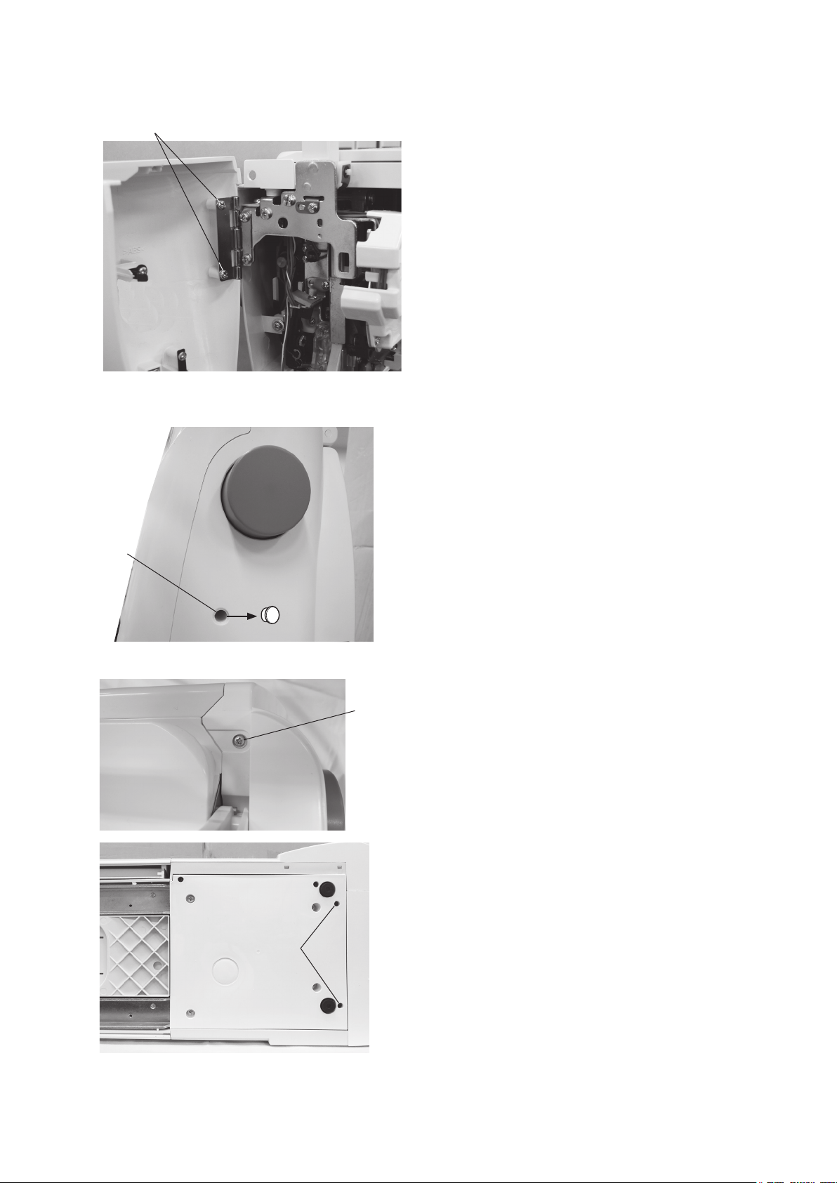
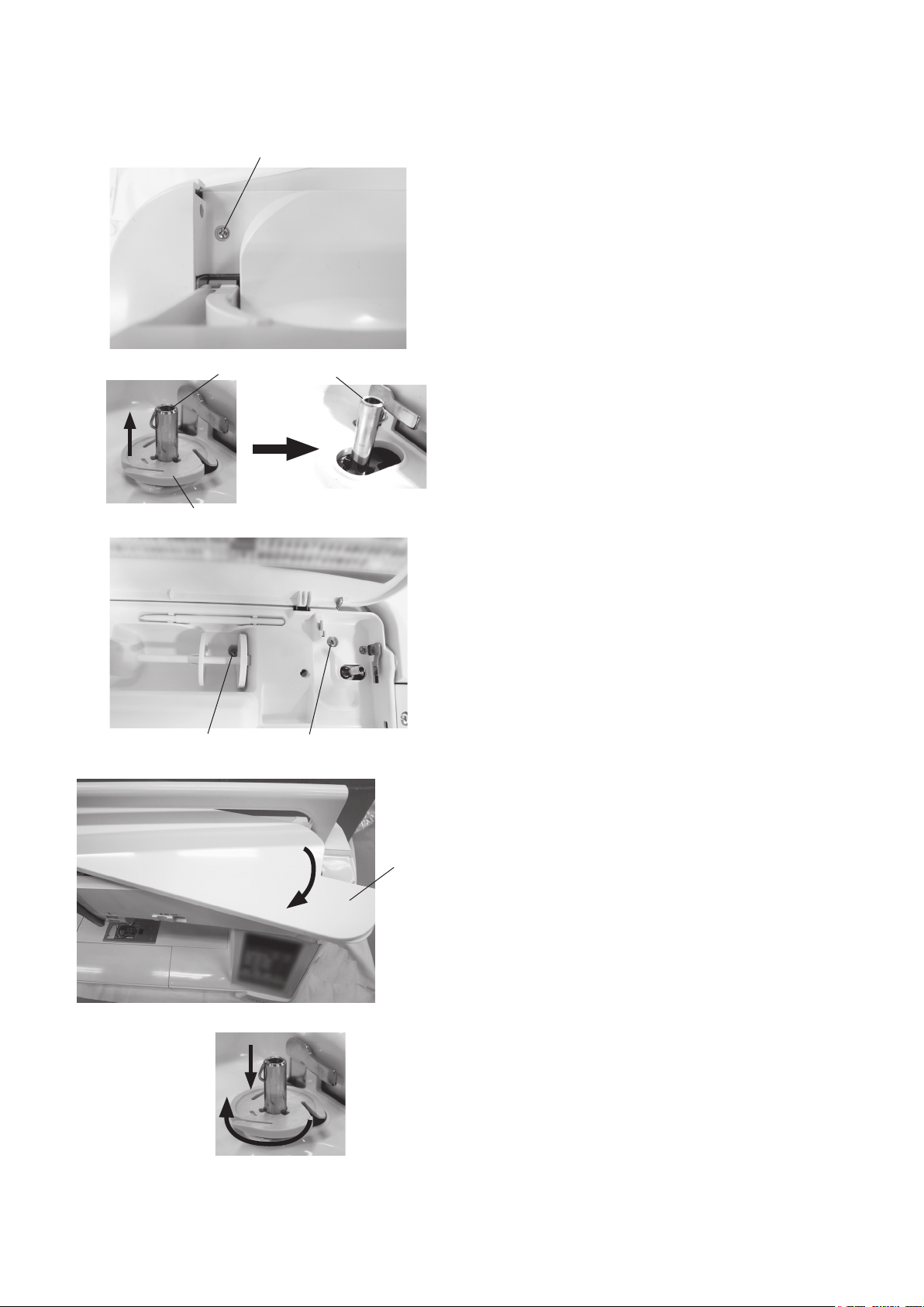
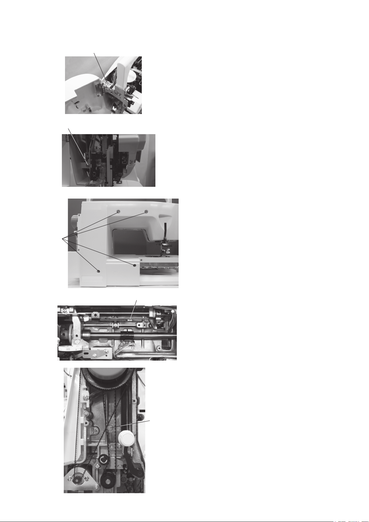
Face cover ......................................................................................................................................................... 1
Belt cover ........................................................................................................................................................... 1
Top cover ........................................................................................................................................................... 2
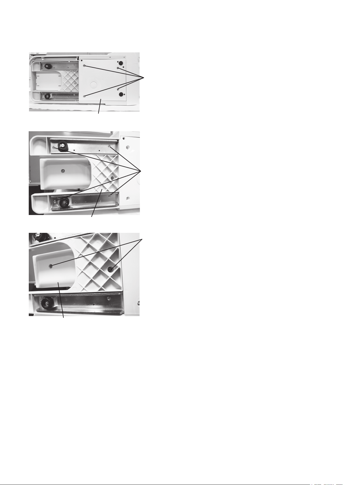
Machine base .................................................................................................................................................... 3
Base cover ......................................................................................................................................................... 3
Bed cover .......................................................................................................................................................... 3
Free arm cover ................................................................................................................................................... 4
Front cover ......................................................................................................................................................... 5
Rear cover .......................................................................................................................................................... 6
Replacing mechanical parts
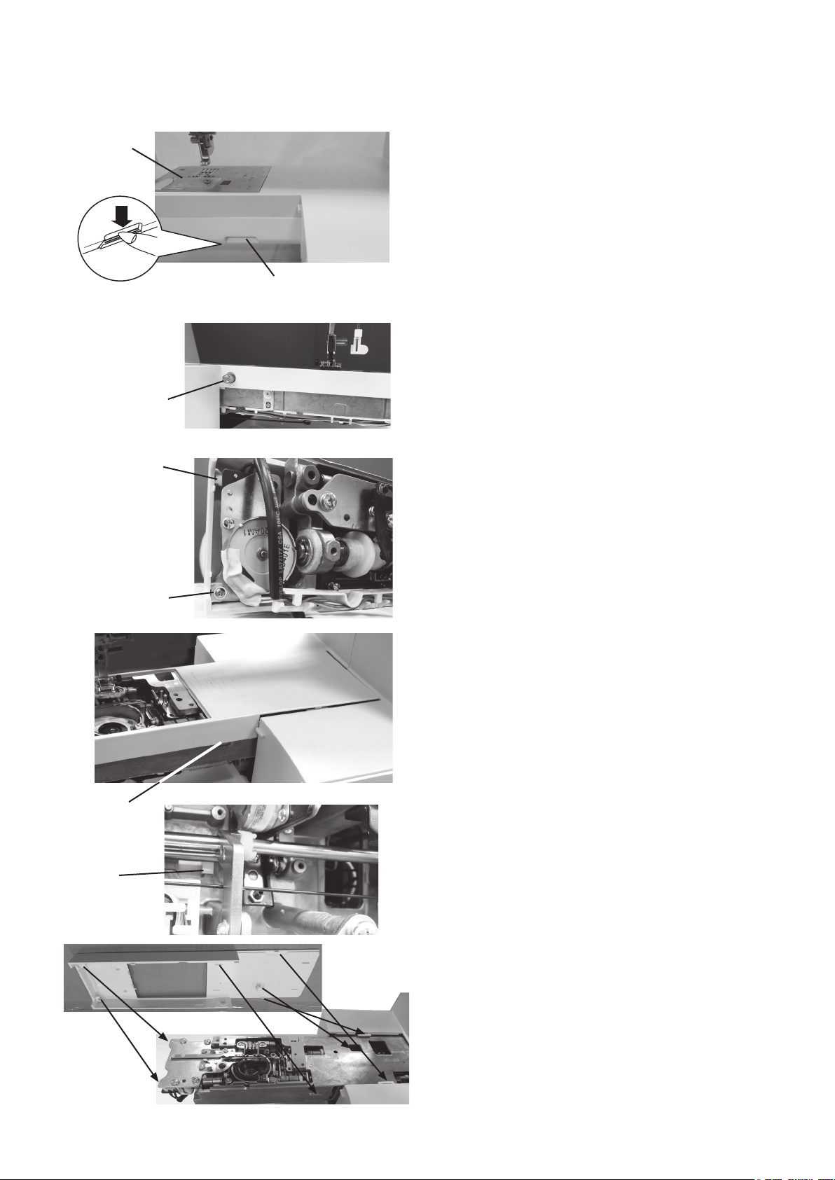
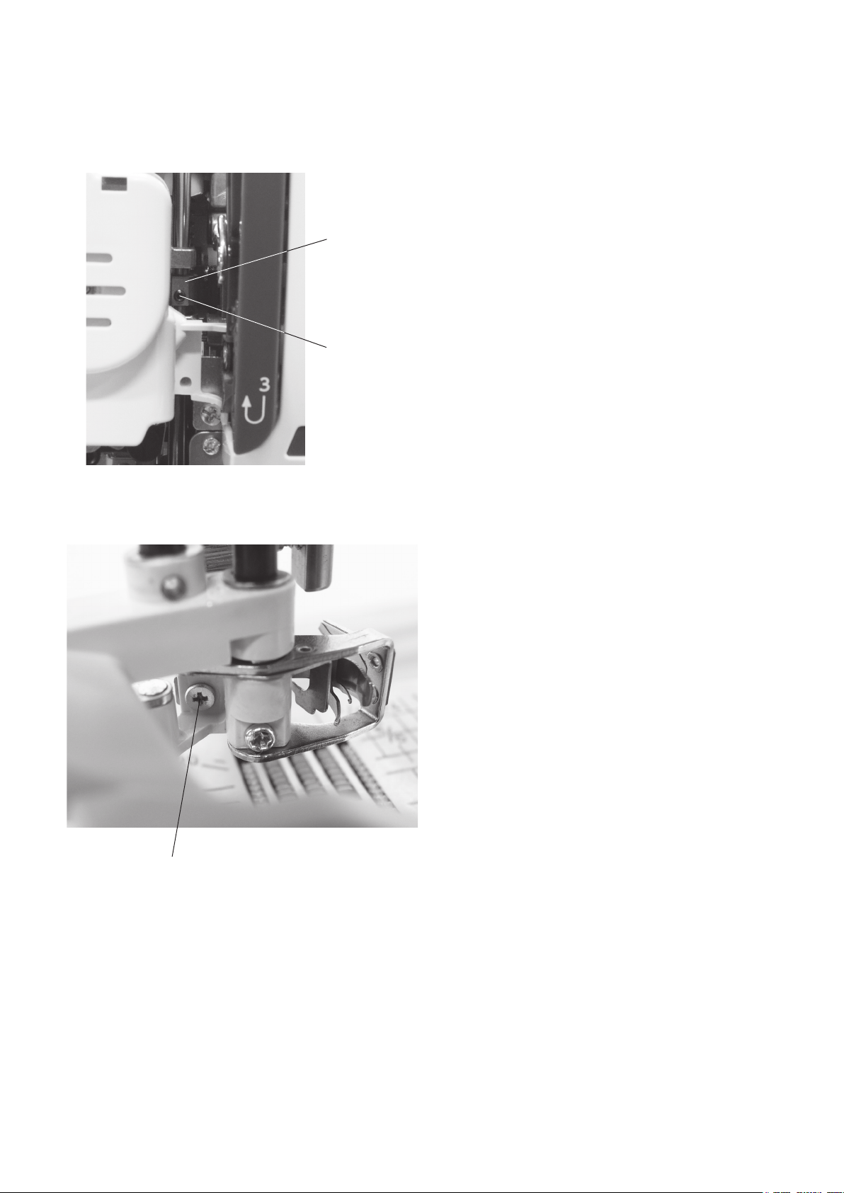
Needle threader hook position .......................................................................................................................... 7
Replacing electronic components
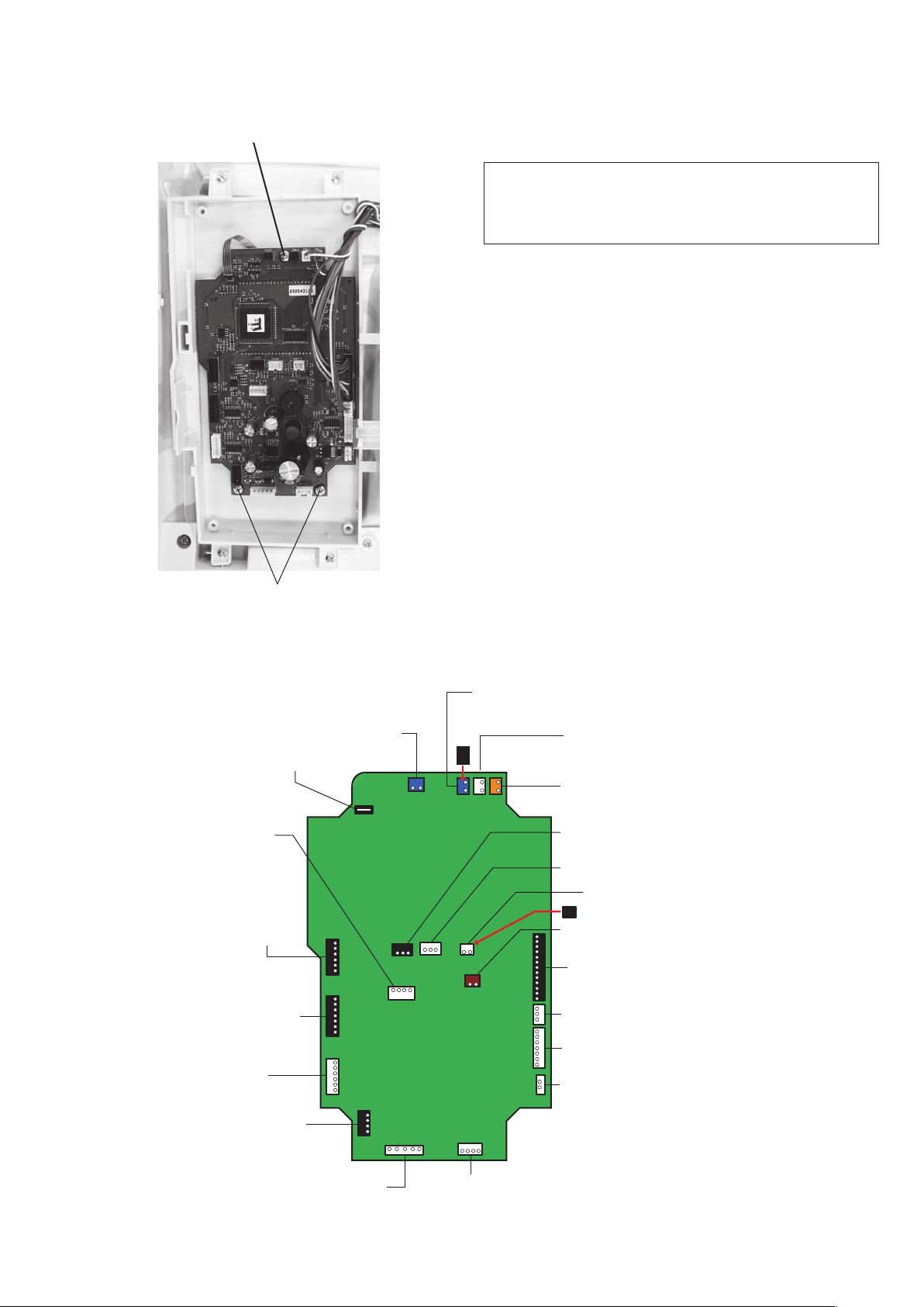
Printed circuit board A ....................................................................................................................................... 8
Printed circuit board F ....................................................................................................................................... 9
Speed control slider ........................................................................................................................................... 9
Switching power supply unit ............................................................................................................................ 10
DC motor ......................................................................................................................................................... 11
Thread tension unit .......................................................................................................................................... 12
Mechanical adjustment
Feed dog height ............................................................................................................................................... 13
Needle drop position ....................................................................................................................................... 14
Presser bar height ............................................................................................................................................ 15
Hook timing ..................................................................................................................................................... 16
Needle bar height ............................................................................................................................................ 17
Clearance between needle and tip of the rotary hook ................................................................................ 18-19
Presser bar lifter switch position adjustment ................................................................................................... 20
Backlash between hook drive gear and lower shaft gear ................................................................................ 21
Upper shaft shield plate position ..................................................................................................................... 22
Upper thread tension........................................................................................................................................ 23
Buttonhole lever adjustment ............................................................................................................................ 24
Thread cutter ................................................................................................................................................... 25
Solenoid position adjustment .......................................................................................................................... 26
Upper feed dog ........................................................................................................................................... 27-29
Stretch stitch feed balance .............................................................................................................................. 30
Needle plate switch ................................................................................................................................... 31-32
Knee lifter posotion .......................................................................................................................................... 33
Diagnosis test ............................................................................................................................................ 34-39
PARTS LIST...................................................................................................................................................... 40-61

1
Replacing external parts
Face cover
To remove:
1. Remove the setscrews A. Remove the face cover.
To attach:
Follow the above procedure in reverse.
Setscrew A
Belt cover
To remove:
1. Remove the cap and setscrew B.
2. Remove the setscrew C.
3. Loosen the two setscrews D.
4. Pull the rear side of the belt cover to disengage it from
the rear cover.
5. Remove the belt cover.
To attach:
Follow the above procedure in reverse.
Make sure all the tabs and hooks t together precisely.
Cap
Setscrew B
Setscrew C
Setscrew D

2
Replacing external parts
Top cover
To remove:
1. Raise the carrying handle and remove the setscrew A.
2. Open the top cover. Pull out the ange plate from the
bobbin winder spindle.
3. Remove the setscrews B and C.
4. Open the face cover. Close the top cover and raise
the carrying handle.
Pull the top cover toward you to remove it.
To attach:
Follow the above procedure in reverse.
To attach the ange plate, put the ange plate on to the
bobbin winder spindle, and push the ange plate down.
Turn the ange plate until it snaps to the pin of the
bobbin winder spindle.
Setscrew A
Top Cover
Face cover
Carrying handle
Flange plate
Bobbin winder spindle
Setscrew B Setscrew C
Top cover

3
Replacing external parts
Machine base
To remove:
1. Remove the setscrews A.
2. Remove the machine base.
To attach:
Follow the above procedure in reverse.
Base cover
To remove:
1. Remove the setscrews B.
2. Remove the base cover.
To attach:
Follow the above procedure in reverse.
Bed cover
To remove:
1. Remove the setscrews C.
2. Remove the bed cover.
To attach:
Follow the above procedure in reverse.
Setscrew A
Machine base
Setscrew B
Base cover
Setscrew C
Bed cover

4
Replacing external parts
Free arm cover
To remove:
1. Remove the machine base and base cover (refer to
page 3). Remove the presser foot.
Push down the needle plate release lever to remove
the needle plate. Remove the bed cover (refer to
page 3).
2. Remove the threaded pin.
3. Loosen the setscrew and unlock the hook A by sliding
the free arm cover to the left.
4. Pull out the free arm cover forcedly to the left while
pulling open the front side to disengage the hook B
and remove the free arm cover.
To attach:
1. Place the free arm cover on the free arm inserting the
hook C into the opening.
2. Insert the right end of the free arm cover under the
front cover by pushing the right end. Push the free arm
cover until all the hooks and tabs snap in place.
3. Follow the steps 1 to 3 of removal procedure in
reverse.
Needle plate release lever
Needle plate
Threaded pin
Hook A
Setscrew
Hook C
Hook B

5
Replacing external parts
Front cover
To remove:
1. Remove the top cover, belt cover, base cover, machine
base and free arm cover (refer to pages 1 to 4).
2. Loosen the setscrews A (underside of the machine).
3. Remove the setscrew B.
4. Loosen the setscrew C (behind the face cover).
5. Loosen the setscrew D (inside of the machine body).
6. Unlock the hooks from the front cover.
7. While pushing the rear cover through the hole A with a
screwdriver, remove the front cover.
Remove the connectors from the circuit board A.
To attach:
Follow the above procedure in reverse.
Refer to page 8 for locating connector posts.
Setscrew A
Setscrew A
Setscrew B
Setscrew D
Setscrew C
Hook
Hook
Hole A

6
Replacing external parts
Rear cover
To remove:
1. Lower the presser foot. Remove the belt cover, top
cover and base cover (refer to pages 1 to 3).
2. Loosen the setscrew A.
3. Loosen the setscrew B.
4. Remove the four setscrews C.
5. Push the rear cover from the holes D and E with a
screwdriver to remove the hook of rear cover.
6. Remove the rear cover.
To attach:
Follow the above procedure in reverse.
Setscrew A
Setscrew B
Setscrew C
Hole D
Hole E

7
Replacing mechanical parts
Needle threader hook position
If the hook of the threader plate is damaged, change or
adjust the part as follows:
1. Push down the threader lever and hold it just before
the threader hook enters the needle eye.
2. If the threader hook is not aligned vertically with the
needle eye, loosen the setscrew A. Adjust the stopper
position so that the hook enters into the needle eye.
Tighten the setscrew A.
Setscrew B
Setscrew A
Stopper
3. If the threader hook is not aligned laterally with the
needle eye, loosen the setscrew B. Adjust the lateral
position so that the hook enters into the needle eye.
Tighten the setscrew B.

8
Replacing electronic components
Printed circuit board A
NOTE:
Do not disconnect connectors by pulling on cord.
To disconnect the connectors, grasp the connector,
not the cord.
To remove:
1. Remove the front cover (refer to page 5).
2. Disconnect the connectors from the printed circuit
board A.
3. Remove the 3 setscrews and printed circuit board A.
To attach:
Follow the above procedure in reverse.
Refer to the board A schematic for locating the
connectors on the printed circuit board A.
After replacing the printed circuit board A, adjust the
following items:
• Knee Lifter (refer to page 37)
• Presser bar height (refer to page 29)
• Embroidery foot height (refer to page 35)
Board A schematic
Setscrew
Setscrew
Slide volume
Printed circuit board L1
(Underside of the arm)
Printed circuit board L2 (Underside of the function buttons)
* Plug the black connector
Touch panel
Bobbin winder switch
Presser foot and
External thread cutter switch
Printed circuit board L2 (Face cover lamp)
BH sensor
Feed motor
Thread cutter motor Solenoid 1
Thread tension release
Phase sensor
Printed circuit
board F
Zigzag stepping motor
DC motor
Program
Needle plate sensor switch
Drop feed switch
Foot control
* Plug the black connector
Power switch

9
Replacing electronic components
NOTE:
Do not disconnect connectors by pulling on cord.
To disconnect the connectors, grasp the connector,
not the cord.
Printed circuit board F
To remove:
1. Remove the front cover (refer to page 5).
2. Disconnect the printed circuit board F connector from
the printed circuit board A (refer to page 8).
3. Remove the CS rings.
4. Remove the setscrews, and the printed circuit board F.
To attach:
Follow the above procedure in reverse.
Speed control slider
To remove:
1. Remove the front cover (refer to page 5).
2. Disconnect the speed control slider connector from the
printed circuit board A (refer to page 8).
3. Remove the 3 CS rings and the speed control slider.
To attach:
Follow the above procedure in reverse.
CS ring
Setscrew
Setscrew
Printed circuit board F
CS ring
Speed control slider
CS ring

10
Switching power supply unit
To remove:
1. Remove the belt cover, the top cover and the front
cover (refer to pages 1, 2 and 5).
2. Disconnect the switching power supply connector
from the switching power supply unit.
3. Remove the foot control connector from the printed
circuit board A (refer to page 8).
4. Remove the setscrews, and switching power supply.
To attach:
Follow the above procedure in reverse.
Replacing electronic components
Switching power supply connector
Setscrew
Foot control
connector (cord)
Setscrew

11
Replacing electronic components
DC motor
NOTE:
Do not disconnect connectors by pulling on cord.
To disconnect the connectors, grasp the connector,
not the cord.
To remove:
1. Remove the belt cover, the top cover and the front
cover (refer to pages 1, 2 and 5).
2. Disconnect the DC motor connector from the printed
circuit board A (refer to page 8).
3. Remove the motor belt.
4. Remove the setscrews (2 pcs), and the DC motor.
To attach:
1. Attach the DC motor and slightly tighten the setscrews.
2. Attach the motor belt and adjust the belt tension.
Push the middle of the belt span with approximately
200 grams-force
pressure. Adjust the motor position so
that the belt deects 5 to 7 mm.
3. Tighten the setscrews securely.
4. Connect the DC motor connector to the printed circuit
board A (refer to page 8).
5. Attach the front cover, the top cover and the belt cover.
Setscrew
Setscrew
Motor belt
200 gf pressure
5 to 7 mm

12
Replacing electronic components
Thread tension unit
NOTE:
Do not disconnect connectors by pulling on cord.
To disconnect the connectors, grasp the connector,
not the cord.
To remove:
1. Remove the belt cover and the top cover (refer to
page 1 and 2).
2. Remove the front cover (refer to page 5).
3. Disconnect the thread tension motor connector from
the printed circuit board A (refer to page 8).
4. Remove the setscrews (A) and (B).
Remove the thread tension (unit).
To attach:
1. Follow the above procedure in reverse.
2. Check the upper thread tension (refer to page 21).
Setscrew A
Setscrew B

13
Nut
Setscrew A Adjusting screw B
Presser foot
0.80 to 0.90 mm
Surface of
needle plate
Feed dog
Hexagonal socket screw
Setscrew D
Threaded hole C
Adjusting screw B Threaded hole C
Setscrew A
Setscrew D
Mechanical adjustment
Feed dog height
When the foot pressure is set at maximum (AUTO+4) and the presser foot A is lowered, the highest position of the feed
dog should be 0.80 to 0.90 mm from the surface of the needle plate.
1. Attach the zigzag foot A. Remove the base cover and
bed cover (refer to page 3).
2. Turn the power switch ON. Adjust the foot pressure to
the maximum (AUTO+4) in the ordinary sewing setting
mode. Adjust the stitch length to the maximum (5.0).
3. Press the presser foot lifter button to lower the presser
foot.
4. Turn the handwheel toward you to raise the feed
dog to its highest position.
5. Loosen the setscrew (A).
6. Loosen the nut with a socket wrench.
Turn the adjusting screw and adjust the feed dog hight
to 0.85 mm.
7. Tighten the nut and setscrew (A).
8. Turn the handwheel and check that the feed dog teeth
are pararell with the surface of the needle plate. If not,
follow the adjustment procedure below.
If the feed dog is not parallel to the surface of the needle
plate at its highest position, make the adjustment as
follows:
* For this adjustment, a hexagonal socket screw 4x6, part
No. 000111108 is required.
1. Insert a hexagonal socket screw part No. 000111108
into the threaded hole (C) until it stops (use an Allen
wrench of 2 mm width across ats).
2. Turn the setscrew D (left hand screw) clockwise to
loosen it.
3. Turn the hexagonal socket screw until the feed dog is
parallel with the surface of the needle plate.
4. Tighten the setscrew D by turning it counterclockwise.
5. Remove the hexagonal socket screw.
6. Attach the bed cover and base cover.
After nishing adjustment, return the foot pressure to
AUTO.

14
Eccentric pin
Eccentricity
Pin
Needle hole
0.2 mm or more0.2 mm or more
A = B
Hexagonal
socket screw
"9.0"
"0.0"
Needle drop position "4.5"
Mechanical adjustment
Needle drop position
When the straight stitch is selected, the needle should be positioned in the center of the needle plate hole.
When the needle drop position is set at "0.0" and "9.0", the clearance between the side of the needle and the needle
hole should be 0.2 mm or more.
1. Attach the #14 needle. Turn the power switch ON and
select straight stitch #1.
2. Check the clearance between the needle and the side
of the needle hole when the needle drop position is set
at "0.0" and "9.0" respectively.
3. If the clearance is less than 0.2 mm, adjust it as
follows.
Loosen the hexagonal socket screw (use an Allen
wrench of 2 mm width across ats).
4. Turn the eccentric pin to get 0.2 mm or more clearance.
The direction of eccentric pin should be as shown.
Tighten the hexagonal socket screw.
Attach the straight needle plate and check if the needle
drops in the center of the needle hole.

15
Should be
parallel
Mechanical adjustment
Presser bar height
The clearance between the presser foot and the surface of the needle plate should be 6 mm when the presser foot is
raised.
The presser foot (zigzag foot A) should be parallel to the slot of the feed dog teeth when attached.
Zigzag foot A
6 mm
Zigzag foot (A)
Slot
Setscrew
To adjust:
1. Attach the zigzag foot (A).
2. Drop the feed dogs.
3. Raise the presser foot with the presser foot lifter.
4. Open the face cover.
Loosen the setscrew on the presser bar supporter to
adjust the presser foot direction as illustrated so
the slot for the feed dog teeth and the zigzag foot
should be parallel.
5. Place the 6 mm spacer (block) between the presser
foot and the needle plate. Tighten the setscrew while
depressing the foot against the spacer.
Needle plate
Presser foot bar supporter

16
Mechanical adjustment
Setscrew A
Bobbin holder
Hook Tip of hook
Hook timing
The amount of ascending travel of the needle bar from its lowest position to the position (Needle drop position 0.0)
where the tip of the rotary hook exactly meets the right side of the needle should be 3.70 to 4.00 mm.
To adjust:
1. Remove the bed cover and base cover (refer to
page 3).
2. Attach the needle #14.
3. Turn the power switch ON. Select straight stitch.
Set the needle drop position at "0.0".
* Do not turn the switch OFF.
4. Remove the presser foot, the needle plate and the
bobbin holder.
5. Turn the handwheel toward you to lower the needle at
its lowest position.
6. Loosen the setscrews A (use an Allen wrench of 2
mm width across ats).
7. Turn the handwheel toward you to raise the needle
bar by 3.85 mm from its lowest position.
8. Turn the lower shaft gear until the tip of rotary hook
meets with the right side of the needle.
Tighten the setscrews A.
* Check the needle bar height after this adjustment.
9. Attach the bed cover and base cover.
3.70 to 4.00 mm
Lowest needle position
Needle #14
Hook
Tip of hook meets the
right side of the needle
(Needle drop position 0.0)
Lower shaft gear

17
Mechanical adjustment
1. Attach the needle #14.
2. Turn the power switch ON. Select straight stitch.
Set the needle drop position at "0.0".
* Do not turn the switch OFF.
3. Remove the presser foot, the needle plate and the
bobbin holder.
4. Turn the handwheel toward you until the tip of hook
meets the right side of the needle.
5. Loosen the hexagonal socket screw (use an Allen
wrench of 2 mm width across ats).
6. Move the needle bar to adjust the needle bar height.
Tighten the hexagonal socket screw.
Be careful not to turn the needle bar.
7. Attach the bobbin holder and the needle plate.
Hexagonal socket screw
Needle setting groove
Needle bar
Needle bar height
The distance between the upper edge of the needle eye and the hook race should be in the range of 1.6 to 2.0 mm
when the tip of the hook meets right side of the needle in the needle drop position "0.0" as the needle ascends from its
lowest position.
1.6 to 2.0 mm
Upper edge of the needle eye
Needle #14
Hook
Tip of hook meets the
right side of the needle
(Needle drop position 0.0)
Hook race
Bobbin holder
Hook Tip of hook

18
Test pin
Tip of hook
-0.10 to +0.05 mm
Left needle position Right needle position
Clearances A and B must be even
A
B
Mechanical adjustment
Clearance between needle and tip of the rotary hook (method 1)
The clearance between the needle and the point of hook should be -0.10 to +0.05 mm.
Needle bar
supporter
1. Remove the top cover (refer to page 2).
2. Remove the presser foot, the needle plate and the
bobbin holder.
3. Remove the presser foot pressure dial.
4. Attach the test pin.
5. Turn the power switch ON while pressing the Start/
Stop button and the Reverse stitch button. The LCD
shows the factory setting mode.
Press "Bobbin" key. The machine will set the zigzag
width at maximum.
6. Turn the handwheel toward you until the tip of the
hook comes behind the test pin.
7. Loosen the hexagonal socket screw (use an Allen
wrench of 2 mm width across ats) and move the
needle bar supporter in the direction of the red arrow
so the test pin just touch the tip of the hook. Tighten
the hexagonal socket screw.
8. Attach the bobbin holder and the needle plate.
Check the needle drop position.
The needle drops in the center of the needle plate
hole as shown.
If the clearances A and B are not even, adjust the needle
drop position rst and then adjust the clearance between
the needle and the tip of the hook by the method (2) on
the next page.
Hexagonal
socket screw
Presser foot
pressure dial
Table of contents
Other Janome Sewing Machine manuals

Janome
Janome ME 4018 User manual

Janome
Janome Memory Craft 500E User manual

Janome
Janome memory craft 7500 User manual

Janome
Janome 204D User manual

Janome
Janome Heavy Duty 1000 User manual

Janome
Janome TS200Q User manual

Janome
Janome MOD-100 User manual

Janome
Janome MXL50 User manual

Janome
Janome DC5100 User manual

Janome
Janome MYEXCEL 18W-MW3018 User manual

Janome
Janome MC400E User manual

Janome
Janome Memory Craft 500E User manual

Janome
Janome DC6100 User manual

Janome
Janome 792PG User manual

Janome
Janome EL2600 User manual

Janome
Janome M100QDC User manual

Janome
Janome Mylock 634D User manual

Janome
Janome MC6600P User manual

Janome
Janome JR1012 User manual

Janome
Janome JD 1818 User manual