Janus Pantheon User manual


2
Pantheon is a low voltage DC mini rolling door operator, manufactured exclusively for and distrib-
uted by Janus International. It is designed to fit neatly inside the torque tube of the rolling door, re-
quiring no additional side room. Pantheon features the latest in electronic technology combined with
innovative engineering and a patented design, and electronic limits can not be “lost” or “erased” in
the event of a power failure or interruption. Pantheon is manufactured to exceed UL325 and CE re-
quirements.
Pantheon is designed to suit a 9 1/2” drum mini series
The Pantheon mini operator is comprised of two parts: a logic controller and a drive unit (with floor
level manual release lever).
Drive Unit Features:
• Low voltage DC motors
• Internal planetary gearing mechanism
• Soft start—soft stop
• Electronic limits
• Floor level—cable operated manual release
• Requires no additional side room for fitment
Integrated Accessories
• Photo electric sensors (photo
eyes)
• External radio receivers and
transmitters
• Programmable 7 day timer
device
• Warning siren/warning light
• Wall switch
• Key switch

3
Low Voltage DC motors
• Thermal overload protection device to UL325
• Quiet, safe and efficient operation
Internal Planetary Gearing Mechanism
• Gear system that provides for great capacity to operate the rolling door
• Motor runs at optimum efficiency—gear system does the “work”
• Ensures smooth operation and promotes long operator service life—tested to 80,000 cycles
Soft Start—Soft Stop
• Software designed to reduce, or soften, the load exerted on the motor during the start of the op-
eration and the stop
• Promotes greater operator service life and ensures smooth operation in both directions
Electronic Limits
• Unique electronic and mechanical design that enables the required opening and closing positions
to be set electronically and retained despite any main power fluctuation or interruption
• Simple three step process—no cams, levers, screws or micro switches
Floor Level—Cable Operated Manual Release
• No power = no lights!
• No need for a ladder
• Simple activation of the lever will enable the door to be operated manually
• Manual activation disconnects power to motor and is monitored on logic controller status
indicator panel
1. Press Learn to Commence
2. Press Up: Move door to
required open position—press
learn to confirm position and
commence learning of closed
position
3. Press Down: Move door to
required closed position—
press learn to confirm position
and commence automatic
check of both settings

4
Twin CPU Processors
• Designed to offer increased operational capacity
• Computing power equivalent to early PCs
• 8 bit processors with 4K x 13 bit OTP ROM
• Processors designed with high speed low power CMOS technology
Plug in Style Terminal
Connectors
• For the simple and reliable con-
nection of all external accessories
• Clearly marked for identification
• Remove
• Connect the appropriate wires
• Replace
UP, DOWN, STOP Buttons and Status Indicator Panel
• Flush mounted buttons
• Illuminated LED status indicator panel
AUTO Close
• Selectable if required for auto closing of the door after a prescribed period
of time
• In the event that the closing sequence is interrupted and the door returns
to the fully open condition, the timer will reset automatically and commence
the countdown process
Momentary or Constant Contact to Close
• Selectable to suit
• V3 boards onwards
• Enabling momentary contact will convert DOWN or closing button to
single contact to operate as opposed to constant or hold to run operation

5
Diagnostic Fault System
• Designed to provide a series of audible “beep” sounds to indicate certain fault conditions
• Simple trouble shooting process intended to quickly identify and resolve fault conditions
• From…No “beep” = check the power is ON
• Right through to Three “beeps” = possible overload condition
Maximum Run Time
• Software will automatically limit the run time of the operator to 60 seconds
• Generally the operating time will be less than 30 seconds
• This feature is intended to prevent damage to the operator in the event of a mechanical problem
with the door or in the unlikely event that the overload or sensitivity software has failed to detect
a fault
Alarm
• Plug in terminal connection provides constant 12 V DC signal in the
event that an attempted forced entry is detected by the operator
• Simple interface with external alarm device—consult alarm manu-
facturers for details
Key Switch—Connection
• Plug in terminal connection for simple wiring of external key switch
device
Timer Device—Connection
• Plug in terminal connection for simple wiring of external timer device
such as may be required to open or close the door automatically during
24 hour (7 day) period
• 12 or 24 V DC power available to suit device
Photo Electric Sensor—Connection
• Plug in terminal connection for simple wiring of photo electric sensor—external
entrapment protection device

6
Edge Sensor Device—Connection
• Plug in terminal connection for simple wiring of two wire edge
sensor—external entrapment device
• NC or NO contact selection
External Receive Device—Connection
• Plug in terminal connection for simple wiring of external receiver device
• 12 or 24 V DC power available to suit device
Electronic Sensitivity
• This feature allows for the characteristics of the door to be effectively
learned by the logic controller
• A curtain size setting establishes the basic operating criteria
• Fine tuning can then be performed—for both opening and closing opera-
tions, and by careful adjustment to ensure that the operator can accommo-
date any variance
Auto Reversing
• An inherent safety feature that, when adjusted correctly in conjunction with the electronic sensi-
tivity, will cause the operator to stop and reverse its downward closing motion if it encounters an
obstruction
• In such an event the operator will detect the obstruction and reverse the direction of the closing
door, returning it safely to the fully open position
• This feature does not replace the requirement for an external entrapment protection device, but
is an added inherent safety feature
Handing Option
• This allows for the drive unit to be fitted to the RH side of the door only
• Although selectable, this must be specified at the time of ordering so that the door may be manu-
factured to accommodate the fully concealed fitment of the drive unit within the torque tube as-
sembly of the door
Fuse Protection
• Replaceable “slow blow” type fuses are fitted where required to provide protection for the circuit
board and where external accessories require DC power from the logic controller

7
Fuse Protection
• Replaceable “slow blow” type fuses are fitted where required to provide protection for the circuit
board and where external accessories require DC power from the logic controller
External Wiring Protection Array
• A specifically designed array of diodes and current limiting resis-
tors intended to limit the effects of poor or incorrect site wiring to
external devices
• In the unintentional event of incorrect wiring connections, the op-
erator will not function
External Entrapment Protection—Monitoring
• Effective as of August, 2010, UL325 will deem that where an ex-
ternal entrapment device is connected as required, it shall be monitored by the software
• The logic controller will not permit the operator to function to close if the entrapment device is
faulty unless the DOWN button is activated by constant contact
Toroidal Transformer
• Superior performance and consistent power supply
• More efficient than traditional “iron block” style
• Manufactured to exceed UL specifications
Main Power Fuse and Isolation Switch
• Designed to allow the qualified technician to switch the main power
when making external connections to the circuit board
• Fuse protection for main supply 110V AC
DC OUTPUT POWER
PROTECTION FUSE FOR
EXTERNAL ACCESSO-
RIES
CIRCUIT BOARD
POWER INDICA-
TOR LED LIGHT
AND PROTECTION
FUSE

The new Pantheon electric door operator from Janus International is a unique new technology designed to make installa-
tion as easy as 1-2-3.
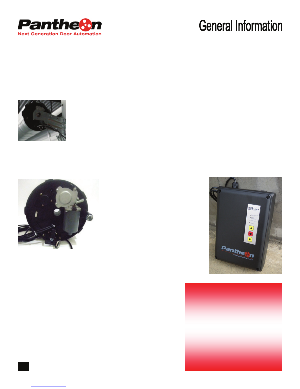
The Janus Pantheon Operator is a stronger and easier to install DC motor operator for today’s door industry, featuring a
simple floor level manual release system, soft start and soft stop operation. The electronic limits of the operator can be
controlled in three easy steps:
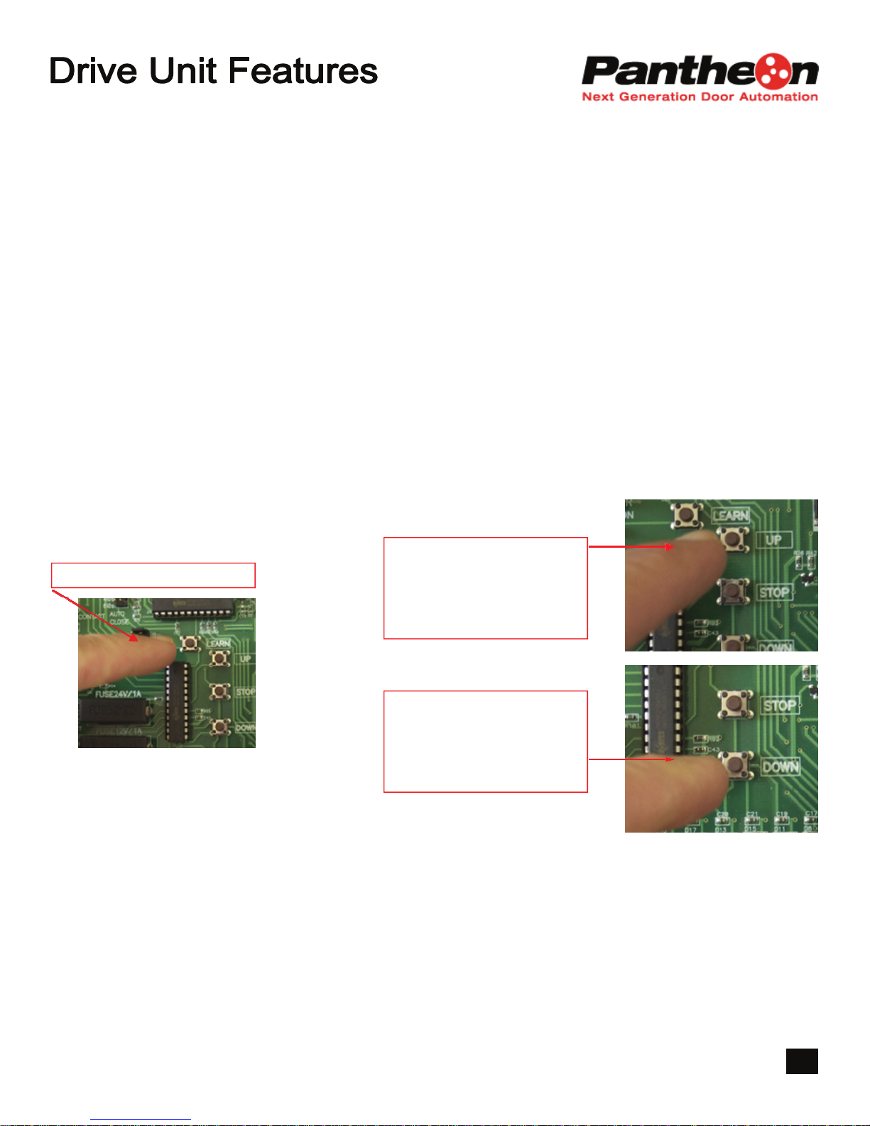
Once in the learn mode -
• Press a “learn” button to move the door to the open position... then
• Press a “learn” button to move the door to the closed position
• Press the “learn” button a final time… and that’s it!
There’s no moving switches or adjusting cams to get the door to open and close to the required position. Setting the lim-
its on the operator is easier than programming a cell phone, and user friendly for anyone to operate. In the event of a
power failure – once the power comes back on the door does not have to be reprogrammed – the logic control retains
the memory and will operate seamlessly.
Key Features and Benefits:
• Pantheon operators use low voltage DC motors, which are more quiet and efficient than standard AC motors.
• In the event that the door needs to be operated in the manual condition, the operator can be converted to manual op-
eration with the simple movement of a lever. The operator is controlled by a logic control which offers a soft start –
soft stop feature, ensuring that the motors are not subjected to undue stress during the starting and stopping se-
quence. The door will come to rest gently and smoothly, helping to prolong the motor life.
• The logic control has individually-controlled opening and closing force adjustments to compensate for small opera-
tional imbalances, which ensures that the door is operating at its optimal level.
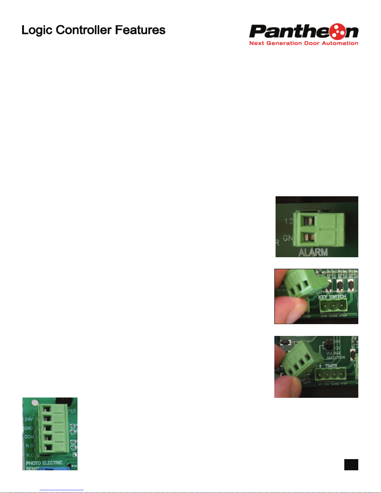
• Connections of external devices are simple and easy to complete with removable plug sockets, which allow the wiring
to be done away from the logic controller and then simply plugged into the required position.
• A specifically-designed receiver unit and radio transmitter can be connected if required to enable the operator to be
controlled by remote control.
• Electronic limits can not be “lost” or “erased” in the event of a power failure or interruption.
• The logic controller has a front panel, which features a simple LED indicator that provides essential status information
as well as UP, DOWN and STOP operation.
• The logic controller has been designed with software and features to ensure that it complies with the new UL325 stan-
dard, effective in 2010.
• Increased strength – the internal reduction gear system enables the motor to lift the door easily, which reduces stress
and prolongs the motor’s life.
• Easier to install – electronic limits help save the installer time and effort
• Floor level manual release – a simple cable device enables the door to easily be switched to manual operation from
ground level.
• Warranty – operators come with a 1 year warranty against defects and workmanship.
• Also available in Commercial (a single motor, 12” version) and HD (a dual motor 12” version)
Pantheon operators are distributed by:
Janus International
134 Janus International Blvd.
Temple, GA 30179
770.562.2850
866.562.2580
770.562.2264 fax
www.janusintl.com
8

INSTALLATION INSTRUCTIONS
COMMERCIAL MODEL
www.janusintl.com

IMPORTANT INSTALLATION SAFETY
THE FOLLOWING SAFETY INSTRUCTIONS RELATE TO THE INSTALLATION OF
THE PANTHEON COMMERCIAL ROLLING DOOR OPERATOR
WARNING !! —TO REDUCE THE RISK OF DEATH OR SEVERE INJURY ALL OF
THE FOLLOWING INSTRUCTIONS MUST BE READ, ACKNOWLEDGED AND
ADHERED TO.
x DO NOT allow children or unauthorized persons in or about the work area when
performing the installation or testing of the rolling door and operator.
x DO NOT attempt to install the rolling door unless you have read , understood and
acknowledged the installation instructions provided for the commercial rolling door.
x DO NOT attempt to install or commission the Pantheon operator or any
accessories unless you have read, understood and acknowledged the instructions
provided.
x ENSURE that all electrical connections for mains power supply are made in
accordance with local and NEC wiring codes.
x ENSURE that the commercial rolling door is installed with correct spring tension
and side clearances—the commercial rolling door must operate in the manual
condition without binding or sticking in the guides.
x INSTALL the logic controller in a suitable location—at a minimum of five (5) feet
from the ground and maximum of three (3) feet from the edge of the opening and
in clear sight of the surrounding areas.
x OBSERVE local and national safety codes—including but not limited to UL325—
when connecting external accessories and any requirement for the installation of
an external entrapment device.
x REMOVE or render inoperable any manually operated locks that may be fitted to
the commercial rolling door.
x REMOVE the factory fitted “test plug” unless required for the purposes of
supervised operation and testing during the installation process.
x ALWAYS complete the commissioning and handover check list and ensure that
the client, site manager or authorized representative is fully instructed in the safe
operation of the commercial rolling door and operator.
x REFER any technical problems or enquiries relating to the commercial rolling door
or the operator to the manufacturer (Janus International ).

IMPORTANT SAFETY INSTRUCTIONS
THE FOLLOWING SAFETY INSTRUCTIONS RELATE TO THE OPERATION OF
THE PANTHEON COMMERCIAL ROLLING DOOR OPERATOR
WARNING !! —TO REDUCE THE RISK OF DEATH OR SEVERE INJURY ALL OF
THE FOLLOWING INSTRUCTIONS MUST BE READ, ACKNOWLEDGED AND
ADHERED TO.
x DO NOT allow children to operate the control panel, wall switch or any remote
control device connected to or designed to operate the rolling door.
x DO NOT attempt to operate the rolling door unless you have a clear and
unobstructed view of the door and the surrounding area.
x DO NOT operate the rolling door if there are children or persons in the vicinity of
the opening—wait until the area is clear before operating.
x DO NOT cross the path of a moving rolling door.
x TEST any safety features of the operator on a regular monthly basis and in the
even that a fault is determined—discontinue use of the door and operator until
such time as the problem is rectified by a qualified technician.
x LOCAL AND STATE safety regulations may require the connection of an external
entrapment protection device when certain optional operational features of the
operator are selected. These include the use of timer devices, auto close feature,
momentary contact to close and the use of remote control transmitters.
x PRIOR TO OPERATING the door—ensure that you are familiar with the full
operational characteristics of the rolling door and operator and understand the
safety requirements.
x DO NOT attempt any repairs, modifications or adjustments to the door or
operator—all such issues should be attended to by a suitably qualified technician.
x IF POSSIBLE only activate the manual release lever when the rolling door is in the
closed position. Weak or broken springs may allow the door to fall rapidly. In all
cases use caution when engaging the manual release.
x IF ANY DOUBT exists with any feature or function of the door or operator—consult
the manufacturer, agent, distributor or authorized installation technician.
x KEEP these instructions in a safe and suitable location for reference and ensure
that all personnel are advised accordingly .

INSTALLATION INSTRUCTIONS
Remove the split nut
Uncoil the manual release cable
and insert the free end of the cable
into the threaded recess
Withdraw (spring loaded) pin and
twist to engage manual release
Fit split nut and tighten
Carefully coil cables together and
secure with a cable tie or similar to
prevent uncoiling or damage during
the installation of the rolling door
STEP 1.
“Connecting the manual
release cable to the drive
unit”

INSTALLATION INSTRUCTIONS
Insert the two steel tubes into
the anchor bracket
Carefully insert the two tubes
of the assembled bracket into
the corresponding sections of
the drive unit
Ensure that maximum
penetration of the tubes into
the drive unit is achieved.
STEP 2.
“Fitting the dual anchor
bracket to the drive unit”
12345

INSTALLATION INSTRUCTIONS
Withdraw the manual release
pin— twist and lock in the
manual condition to allow the
drive unit to rotate freely
The drive unit is fitted inside
the drum assembly of the
rolling door
Carefully slide the drive unit
along the axle of the rolling
door on the appropriate end of
the door—the steel drum
wheel is recessed during the
manufacture of the door to
accommodate the fitment of
the drive unit
Ensure that the spigots on
the back of the drive unit are
engaged with the
corresponding holes in the
steel drum wheel
STEP 3.
“Preparing for the
installation of the rolling
door”
PARTS AS SHOWN
EXPOSED FOR
PURPOSES OF
HIGHLIGHTING THE
FITMENT OF THE
SPIGOTS THROUGH
THE DRUM WHEEL

INSTALLATION INSTRUCTIONS
Ensure the drive unit is correctly fitted
inside the door drum assembly and
fully engaged in the steel drum wheel
Install the rolling door to the door
brackets as outlined in the Janus
installation guide
Spring tension and curtain clearances
should be maintained as per normal
practice
A U-bolt & nuts are provided with a
cast iron saddle to secure the axle of
the door to the support bracket
STEP 4.
“Proceeding with the
installation of the rolling door”
NOTE OF CAUTION !
Take care to ensure that the
cables from the drive unit are
not damaged or permitted to
bind on any part of the
structure or the door during the
installation

INSTALLATION INSTRUCTIONS
STEP 5.
“Fitting the logic controller”
Carefully uncoil the cables from the drive unit and locate them such that
they are protected from any mechanical damage
Locate a suitable position for the fitment of the logic controller ensuring
adequate free cable length
The logic controller shall be installed on the same side of the opening as
the drive unit
The logic controller shall be installed at a minimum of five (5) feet from the
ground and a maximum of three (3) feet from the edge of the opening and
with a clear view of the surrounding area
The front cover is secured with four captive screws
If required—carefully unplug the main control panel loom plug from the ter-
minal
NOTE OF CAUTION !!
Connect the mains power in strict accordance with all local and NEC
wiring codes

INSTALLATION INSTRUCTIONS
Once the logic controller enclosure is
secured to the structure—locate the drive
unit cable and the electronic limit cable.
Fit the electronic limit cable plug through the
hole provided at the bottom of the
enclosure—use care to ensure correct
fitment
Fit the cable gland & strain relief bushing to
the four wire drive unit cable and fit the cable
through the hole provided at the bottom of
the enclosure—remove the plug in section of
the terminal and connect the wires in
accordance with the detail provided
As per factory issue—the logic controller is
designed to operate with momentary contact
to OPEN and constant contact to CLOSE
STEP 5.
“fitting the logic controller….(continued)”
Cable gland & strain relief bushing

INSTALLATION INSTRUCTIONS
The Pantheon logic controller is
designed to operate the drive unit
when fitted to either LH (left hand)
side or RH (right hand) side
installations – as viewed from inside
looking outward.
To correctly hand the logic controller
to match the drive unit installation –
move the DIRECTION jumper to the
required position.
LH OPERATION
RH OPERATION
NOTE OF CAUTION !!
ALWAYS SWITCH MAINS POWER OFF WHEN HANDING THE OPERATOR
STEP 6.
“Handing the operator to suit
the installation — LH or RH
side drive“
This handing feature does not
apply to Pantheon “mini “ -
operators
All Pantheon “mini “operators will have the
direction jumper removed and fitted to the
JSS (Mini) position – as standard factory
issue

INSTALLATION INSTRUCTIONS
Ensure the drive unit is engaged for normal
“auto” operation and the power is ON.
1. Press and hold LEARN button until three
BEEP sounds are heard
The logic controller will learn the OPEN position
FIRST
2. Press and hold the UP button until the door
moves to the required OPEN position
Small adjustments may be made by momentary pressing of the UP
or DOWN button to move the door to the required position
Do not allow the bottom bar of the door to contact the head stops
3. When the OPEN position is achieved – press
the LEARN button once – two BEEP sounds will
confirm the setting.
The logic controller is now ready to learn the
CLOSED position.
4. Press and hold the DOWN button until the
door moves to the required CLOSED position
Small adjustments may be made by momentary pressing of the UP
or DOWN button to move the door to the required position
5. When the CLOSED position is achieved –
press the LEARN button once – two BEEP
sounds will confirm the CLOSED setting— the
operator will perform an automatic check of both
settings
1“learn”
2“open position”
5“confirm settings”
STEP 7.
“Setting the electronic limits”
4“closed position”
3“confirm & learn”

INSTALLATION INSTRUCTIONS
The Pantheon logic controller is designed to
electronically detect and monitor the normal
operation of the door.
This ensures that the operator shall
automatically stop and reverse its closing
motion or alternately stall its opening motion
if an obstruction is detected.
To set the sensitivity adjustment—position
the jumper at Sand check that the door will
operate without reversing or stalling.
If required move the jumper through the
ranges M, L& XL until satisfactory operation
is achieved.
Final adjustment of the sensitivity setting is
performed by following the instructions as set
out under the heading SENSITVITY
ADJUSTMENT (step 9).
NOTE OF WARNING !!
IT IS ESSENTIAL THAT THIS FEATURE IS NOT RECOGNISED AS AN
EXTERNAL ENTRAPMENT PROTECTION DEVICE AS MAY BE
REQUIRED TO SATISFY NATIONAL SAFETY CODES INCLUDING, BUT
NOT LIMITED TO UL325
STEP 8.
“Setting the sensitivity adjustment”
Table of contents
Other Janus Garage Door Opener manuals
Popular Garage Door Opener manuals by other brands

Grifco
Grifco eDrive +2.0 Installation and user manual

Chamberlain
Chamberlain Merlin Professional MT230 Installation and operating instructions

Overhead door
Overhead door 555 Installation instructions and owner's manual

CAME
CAME VLR01DX installation manual

Chamberlain
Chamberlain 2580 1/2 HP owner's manual

tau
tau T-SKY Use and maintenance manual

Chamberlain
Chamberlain 8500W-267 instruction manual

Aprimatic
Aprimatic SLIDE 230 Electrical installation, Use and Maintenance instructions

Automatic Technology
Automatic Technology SecuraLift Trio installation instructions

Craftsman
Craftsman 41A638-1 instructions

BOXER
BOXER 63.002 user manual

Nice
Nice Soon manual