Jatontec JT8500D User manual

Page 1
JATONTEC JT8500D LTE-A Pro
CAT12 Outdoor CPE
Administrator User Manual V2.0

Page 2
PLEASE READ THESE SAFETY PRECAUTIONS!
RF Energy Health Hazard
The radio equipment described in this guide uses radio frequency transmitters.
Although the power level is low, the concentrated energy from a directional
antenna may pose a health hazard.
Do not allow people to come in close proximity to the front of the antenna while the
transmitter is operating.
Protection from Lightning
Before connecting this instrument to the power line, make sure that the voltage of
the power source matches the requirements of the instrument. The unit must be
standards.
Disposal and Recycling Information
Pursuant to the WEEE EU Directive electronic and electrical waste must not be
disposed of with unsorted waste. Please contact your local recycling authority for
disposal of this product.
Reduction of Hazardous Substances
This CPE is compliant with the EU Registration, Evaluation, Authorization and
Restriction of Chemicals (REACH) Regulation (Regulation No 1907/2006/EC of the
European Parliament and of the Council) and the EU Restriction of Hazardous
Substances (RoHS) Directive (Directive 2002/95/EC of the European Parliament and of the
Council).

Page 3
Table of Contents
1. OVERVIEW................................................................................................................................................5
USER INTERFACE SPECIFICATION .....................................................................................................5
2. GETTING STARTED................................................................................................................................5
DEVICE LOGIC CONNECTION .............................................................................................................6
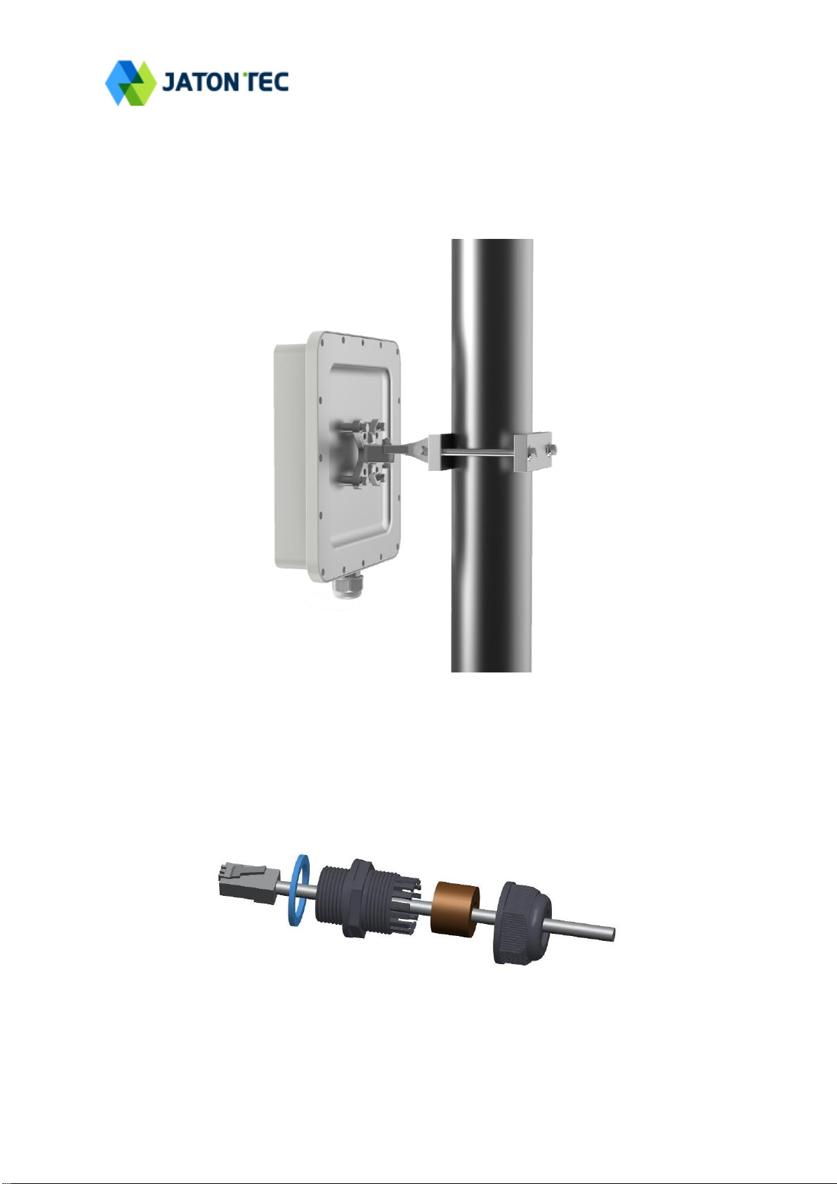
INSTALLING MOUNTING BRACKETS...................................................................................................7
HEADER CONNECTION.......................................................................................................................7
2LED DISPLAY ...........................................................................................................................................8
RF SIGNAL ADJUSTMENT ..................................................................................................................8
3MANAGING CPE DEVICE .....................................................................................................................8
WEB LOGIN........................................................................................................................................9
4LTE CONFIGURATION ...........................................................................................................................9
OVERVIEW ..........................................................................................................................................9
ND&S CONFIGURATION .................................................................................................................. 11
PLMN SELECTION ...........................................................................................................................11
CELL SELECTION .............................................................................................................................11
PDN SETTING ..................................................................................................................................12
SIM CARD ........................................................................................................................................12
ADVANCED........................................................................................................................................13
LTE SMS..........................................................................................................................................14
COMMAND SHELL.............................................................................................................................14
5NETWORK CONFIGURATION ...........................................................................................................15
INTERNET..........................................................................................................................................15
LAN SETTING...................................................................................................................................16
VPN SETTING UNDER ROUTER MODE ...........................................................................................17
VPN SETTING UNDER L2 BRIDGE MODE .......................................................................................19
L2 SERVICE UNDER L2 BRIDGE MODE...........................................................................................20
QOSSETTING ..................................................................................................................................20
DDNS SETTING UNDER ROUTER MODE ........................................................................................21
TRAFFIC CONTROL SETTING UNDER ROUTER MODE ....................................................................21
6SECURITY CONFIGURATION............................................................................................................22
FIREWALL .........................................................................................................................................22
ALG ..................................................................................................................................................22
DEFENSE...........................................................................................................................................23
ACCESS RESTRICTIONS...................................................................................................................24
7APPLICATIONS CONFIGURATION ..................................................................................................25
PORT RANGE FORWARDING ............................................................................................................25

Page 4
PORT FORWARDING .........................................................................................................................25
DMZ .................................................................................................................................................25
UPNP................................................................................................................................................26
PORT TRIGGERING ...........................................................................................................................26
8MANAGEMENT ......................................................................................................................................27
DEVICE MANAGEMENT.....................................................................................................................27
TR069..............................................................................................................................................28
SNMP...............................................................................................................................................28
9MAINTENANCE .....................................................................................................................................29
GENERAL..........................................................................................................................................29
FIRMWARE UPGRADE.......................................................................................................................29
CONFIG MANAGEMENT ....................................................................................................................30
PING..................................................................................................................................................31
IPERF.................................................................................................................................................31
SYSTEM RESET.................................................................................................................................32
10 STATUS....................................................................................................................................................33
SYSTEM.............................................................................................................................................33
NETWORK .........................................................................................................................................34
LAN ..................................................................................................................................................35
11 FAQ AND TROUBLESHOOTING .......................................................................................................36

Page 5
1. Overview
JATONTEC 8500D is highly advanced LTE-A Pro CAT12 outdoor data unit specially
designed to meet the most challenging demands of today’s high speed wireless
backhaul and fixed wireless access deployments by the 4G service operators. The unit
can support multiple TDD band operations. Multiple operator network support can also
be provisioned on the unit to allow the deployment across entire country with different
operators.
User Interface Specification
Model
Description & User Interface
JT8500D
- Panel antenna: 17dBi (2*2 MIMO 4CA),
13dBi (4*4 MIMO 2CA)
- 1 RJ45 10/100/1000M LAN Port
- PWR, SYS, SIM, LINK, ACT, and LTE (1-5) LEDs
- 48V/0.5A PoE supply, ODU Power <15 Watts
- Dimensions: 250 mm (L) × 250 mm (W) × 75 mm (D)
- Weight: <2.5 Kg
2. Getting Started
1) Packing list
Upon receiving the product, please unpack the product package carefully. Each product is
shipped with the following items:
Table 2-1 Packing List
Outdoor CPE Products
Quantity
ODU unit
1
PoE adapter
1
Power cord
1
Mounting brackets
1
PC Ethernet Cable
1
If you find any of the items is missing, please contact our local distributor immediately.
2) Unpacking the Equipment
Table 2-1 lists all the standard parts that are supplied in your LTE CPE Unit Installation
Package. Please take the time to unpack the package and check its contents against this list.

Page 6
3) Installing the Equipment
Device Logic connection
For outdoor CPE product, it is suggested that the CPE device be installed in a shaded area to
avoid direct sun light exposure which may cause over heat in certain extreme weather
condition.
To power on the device, the outdoor CPE must use a 48V PoE integrated DC power supply
adapter. The power adapters can operate in 100-240V AC range and therefore can be used
in different country. Once the device is powered up, the user should wait for about 1 minutes
before the device becomes operational. When the RF1 LED becomes blinking green, it
indicates the system has completed the startup procedure.
To connect PC, LAN switch or other type of IP device to the CPE product, the user should use
SFTP CAT5E Ethernet cable and connect to the appropriate LAN port. Once connected, the
ETH LED indicator should come on.

Page 7
Installing Mounting brackets
Header Connection

Page 8
2LED Display
Type
LED
Function
Description
ODU
PWR
Power indicator
Solid green –Device is power on.
SYS
System run indicator
Solid green –Device is in normal operation.
SIM
SIM card indicator
Light is on –SIM card state is ready,
Blinking Green –SIM card is error.
LINK
LAN port status
Solid Green –LAN port is up.
ACT
LAN port status
Blinking Green –LAN data transmission.
RF
(5LEDs)
RF Signal Strength
5 level signal strengths indication by 5 green
LEDs.
1st Green LED: -115dBm < RSRP
2nd Green LED: -115dBm <= RSRP < -105dBm
3rd Green LED: -105dBm <= RSRP < -95dBm
4th Green LED: -95dBm <= RSRP < -85dBm
5th Green LED: -85 <= RSRP
RF Signal Adjustment
After the CPE outdoor unit has installed, the direction of antenna’s azimuth and pitch angle
needs to adjust for the best signal strength. In near line of sight condition, the CPE will have
the best signal when the antenna is directly pointing the base station.
User can adjust the holder to change the direction and angle of the antenna while observing
the RF LED on the outdoor unit which indicates the signal strength.
3Managing CPE Device
JT8500D is a user-friendly LTE CPE, and very easy to configure and setup. Subscribers can
just connect the device to their computer or home switch/router and the device is ready to
provide Internet Services.

Page 9
WEB Login
It is a preferred to setup the CPE using a Web browser from a local PC connected to device
LAN port. The user should ensure that the connected PC have acquired IP address via DHCP
from the device. After IP connectivity is established between the PC and CPE device, the
user may launch a Web browser and specify http://192.168.0.1 in the address bar. A window
will pop up requesting password. Input the user or administrator login password and then
click the “Log in” button. After successful log on, the default home page will appear. Note the
default user & administrator passwords are “user123”and “admin123” respectively.
4LTE Configuration
Overview
Once the user is logged in, the following window device status window will be prompted for
viewing. It contains both the system information, networking and device information
configured for the device.

Page 10

Page 11
ND&S Configuration
The LTE radio can be enabled or disabled via 4G Radio setting. The radio can also be reset
via Reconnect.
Note: After configure any parameters of the device, you must click the “Save & Apply”
button to save the configuration. Otherwise the configuration will not take effect.
PLMN Selection
The user can add and configure the PLMN list to restrict the CPE to attach. The CPE will
attach to network according to the PLMN priority assigned.
Cell Selection
The cell selection menu is used to configure how CPE will select the best cell. User can
configure the “Auto Select” mode to select cell based 3GPP standard. When configured with

Page 12
“preferred Listing”, user add the desired cell ID to the list and the CPE will attach to the
appropriate cell after a full scan.
PDN Setting
This menu is used to configure the operator APN profile. You can configure single or multiple
APNs for the operator network. The below shows an example of two APN configuration.
You can view the APN status info in the Status menu.
SIM Card
The SIM card menu is used to view the SIM card status and perform PIN code management
for SIM card. You disable or enable the SIM card PIN check on the CPE to bind the SIM card
inserted.

Page 13
Advanced
In this menu, you can configure advanced options for the CPE operation.
Fast scan will allow you to quickly connect to good cell when they are first found instead of
search the best cell. The ZUC encryption support is only required when your core network
(EPC) force to use the ZUC encryption for access authentication. The operation mode allows
you to select the UE capability for receiving and transmitting. Depending on the hardware
implementation, 4x4 MIMO or 2x2 MIMO & CA can be selected for downlink operation. If the
RF hardware supports 2TX, then 2Tx operation can be enabled.
In addition, the PSM timer and location service UE settings can also be configured for
advanced users. Default settings should be used for normal operation.

Page 14
.
LTE SMS
The LTE SMS page allows user to retrieve and display short messages received by the UE
device. Message format, storage place and message filter can be configurere to screen and
archieve the messages.
Command Shell
The Command Shell is used to run LTE command via the WEB GUI interface. You can type the

Page 15
command and click the APPLY button to execute.
5Network Configuration
Internet
This section allows user to configure the CPE operation mode, device name, MTU and etc.
The CPE default Operation Mode is Router, and the LAN PC connected to device LAN port will
obtain IP address via DHCP server of the device. The default MTU Size is 1500, user can
modify the MTU Size if necessary.

Page 16
Note when setting the connection mode as L2 Bridge or L3 Bridge, there will be a
warning window pops up. Remember the management IP address 192.168.0.1 and click
the “ok” button.
When the user wants to manage the home page again, the PC should be configured a
static IP address as 192.168.0.x manual in order to visit the CPE managing page
http://192.168.0.1.
LAN Setting
The LAN setting allows user to specify the device LAN IP, DHCP server setting, Local DNS
and etc. When Router mode is selected, the DHCP server should be enabled by default.
User is advised to leave the default setting unchanged for quick configuration and smooth
device operation.

Page 17
VPN Setting Under Router Mode
This section allows user to configure VPN service for selected connection mode. In router
mode, PPTP, L2TP and GRE can be selected. In L2 Bridge mode, only L2 GRE can be
configured.

Page 18
The router mode VPN configuration is shown below.
The PPTP configuration under router mode is shown below.
The L2TP configuration under router mode is shown as follows.

Page 19
The L2 GRE configuration under router mode is shown below.
VPN Setting Under L2 Bridge Mode
Under the L2 Bridge connection mode, only L2 GRE can be configured as follows.

Page 20
L2 Service Under L2 Bridge Mode
Under the L2 Bridge connection mode, the user can use L2 Service configuration to manage
and tag 802.1p or DSCP for different VLAN packets.
QoS Setting
This configuration menu allows user to tag DSCP or TOS value for CPE local data
(Management) and LAN port data (Data).
Table of contents
Other Jatontec Antenna manuals
Popular Antenna manuals by other brands

Beam
Beam RST720 installation guide

Parsec Technologies
Parsec Technologies ST. BERNARD installation instructions

Sea Tel
Sea Tel 9711-44 KU-BAND TX/RX Installation and operation manual

RF Elements
RF Elements Sector Carrier Class 5-17 installation guide

Hughes
Hughes AN6-098P installation manual

Megasat
Megasat Countryman GPS user manual