1
v. ., : -. :
>
,‘. . ..: ._ ; _. .. .
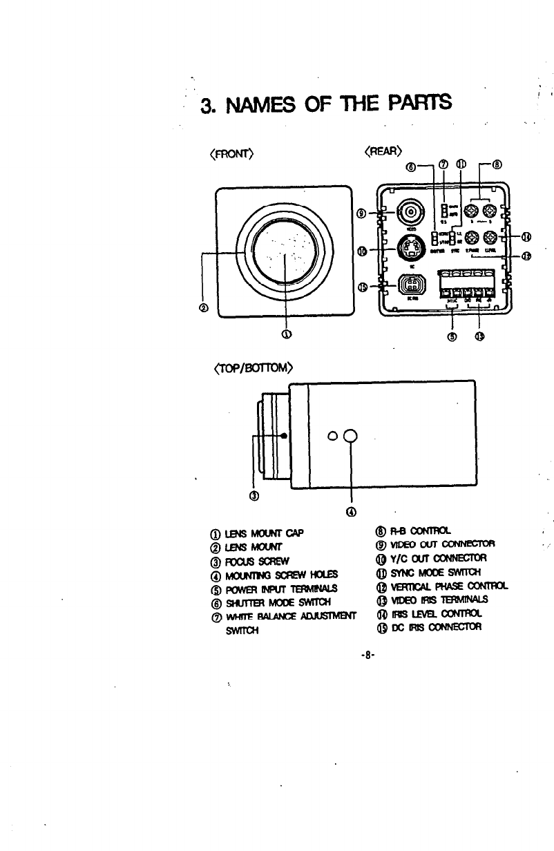
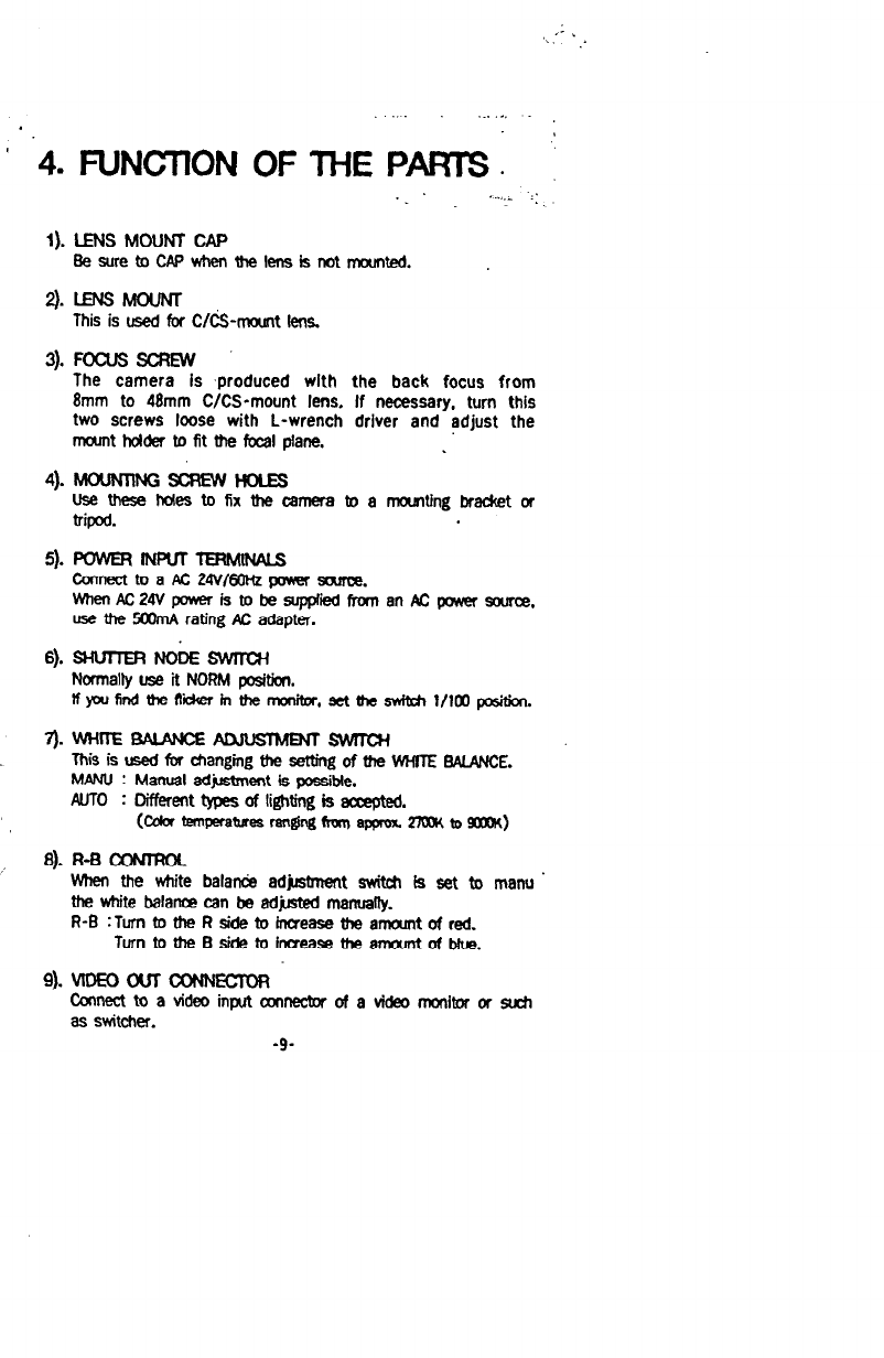
10). Y/C OUT CoNNEcToR
Outputmector for separatedY/C tide0
signals.
Connectto the S-VIDEOinput cxmnecWof a video monitor, etc.
Y/C OUT
C(Chrominance.0.286Vp-p
11). SYtx h4ooE wrrai
The internal (INT) sync mods OTline-W (LLOCK) sync mode
selectionsac4l.
LUCK : In lhe Ill-bdt sattin& the camera’s
vertical synchro-
niratlon can be driven by the 60Hr AC .signal in the
powerIll
.12). VEHlwl PHASE m
lfthecamerais~bausedinttleline-kxked’mode,vartjcal
phase is adJ&able owr the range of -90’~-i-W.
* Whan AC power line frequmcy is %Hz. the line-lock sync
opsration is not pcssibIe.
* In the line-k& sync mode, sytwhronization may not be
uxrectforafewsecondsafterthapowristuwwJon;this
tsnotamaKmctim
13).vDEo Rt!3 TERMuwS
-CormectthalRlScableofanvb9eoirislens.
Pln
asalgnment: VIDEOIRIS oonnector(3-pin)
GND IRIS tSV
-IO-
, I’
.’ i
_.-. I . .
-
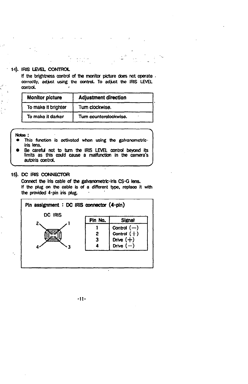
14). IFUSLEVELCONTFKn
If the brightness
csmtrd
of the monitor picture does not operate .
correctly, adjst using Ute amtrol.
To adjust the IRIS LEVEL
amtrd. I
1 Monitor ~ictura 1 Adlustment dIrectton
To make it brighter Turn clockwise.
To make it darker Turn oounterctockwise.
15). DC INS amEcmt3
fhnecl tha iris
cable of tha galvanmwW-iris CS-0 lens.
If the plug on the cable is of a different type, replace it with
the provided4-pin iris plug. ’
I
Pin asskrunent : DC IRIS amnectnr
(4-pin)
DC IRIS
Pin No.Pin No. 1 SignetSignet
11 control (-)control (-)
22 ZFZF
3 .3 .
44 Drive(-)Drive(-)
-II-