Jaybird CoolAireMist COOL-101 User manual

OPERATOR’S MANUAL
Read & Understand
Retain for Future Reference
NOTICE
Mobile Mist Cooler
►
COOL-101
►
COOL-102

Notes
Purchase Date Model ID Number
Vendor Information

General Safety . . . . . . . . . . . . . . .
Unpacking & Setup . . . . . . . . . . .
Operation & Maintenance . . . . . .
Troubleshooting . . . . . . . . . . . . . .
Service & Repair . . . . . . . . . . . . . .
Electrical Schematic . . . . . . . . . .
Replacement Part ID . . . . . . . . . .
Warranty . . . . . . . . . . . . . . . . . . . .
PAGE
3
4
5
6
7
8
9
10
This manual contains very important information. This information will
help ensure SAFETY and PREVENT EQUIPMENT PROBLEMS. Below are
important safety guidelines.
DANGER
WARNING
CAUTION
NOTICE
Aquafog (CoolAire) mobile
units are intended to
condition large volumes of
air using water or other
non-hazardous liquids at
air temperatures between
33ºF and 145ºF. Any other
use of this unit would
likely void the warranty
and any manufacturer’s
responsibilities.
THE COOLAIRE MIST CAN BE AUTOMATED WHEN USED
IN CONJUNCTION WITH A CONTROL. THE FAN MAY NOT
APPEAR POWERED BUT COULD SUDDENLY BEGIN HIGH-SPEED ROTATION AS A
FUNCTION OF THE PRESET CONTROL.
HIGH-SPEED ROTATION, NEVER OPERATE UNIT WITHOUT
THE HOUSING AND SAFETY GUARDS INSTALLED.
GROUND FAULT RECEPTACLES ARE STRONGLY
RECOMMENDED AND MAY BE REQUIRED BY LAW.
A WATER RESERVOIR (COOLAIR’S TANK) CAN BRING
THE RISK OF DROWNING. DROWNING ACCIDENTS CAN
BE PREVENTED WITH PROPER PRECAUTIONS, SUPERVISION AND KNOWLEDGE.
CHILDREN CAN DROWN IN LESS THAN ONE MINUTE. PERSONNEL WORKING WITH
COOLARIE MIST SHOULD BE PROPERLY TRAINED.
TABLE OF CONTENTS PRODUCT USE
SAFETY NOTIFICATIONS

Read operator’s manual carefully and thoroughly. Understand all safety
warnings and instructions before attempting operation of the unit.
DO NOT OPERATE THE PUMP DRY (WATER SUPPLY IS REQUIRED IN THE
SUMP). Avoid permanent damage to the unit’s sump pump. Turn off
“MIST” (pump switch) to operate the unit air only.
Follow all local electrical and safety codes as well as the United States
National Electrical Codes (NEC) and Occupational Safety and Health Act
(OSHA).
Keep children from playing with CoolAire Mist. Supervise nearby children
or blockade area to prevent children from accidentally falling into the
tank. Keep the lid installed.
Always operate CoolAire Mist with it's safety guards, housing and lid
securely in place. Use front wheel locks at all times.
Disconnect power before inspecting or servicing machine. CoolAire Mist
must be properly grounded as a precaution against possible electric
shock. Check for correct voltage supply.
Keep cord away from heat, oil, sharp edges and moving parts. Replace
damaged cords immediately. Damaged cords increase the risk of electric
shock.
If using an extension cord. Use a heavy gauge 3 wire extension cord with
a molded three-prong plug rated for outdoors.
Keep hands and all objects from entering the path of the blade.
Use fresh water supplies. Do not use ammable liquids, caustic
materials, or corrosive materials with the CoolAire Mist.
When servicing CoolAire Mist, use only identical replacement parts and
follow instructions in the maintenance section of this manual. Use of
unauthorized parts or failure to follow maintenance instructions may
damage equipment or cause personal injury.
GENERAL SAFETY
1.
2.
3.
4.
5.
6.
7.
8.
9.
10.
11.
The CoolAire Mist uses a high-speed component
to atomize water and a water reservoir to hold
water supplies. The following safety precautions
must be observed at all times:
3

Receiving your CoolAire Unit
Locate and remove the screws securing the
box to the skid. Lift and save the box incase
a return is necessary. Remove the strapping
and unpack the unit. Inside the tank locate
the following:
1) Atomizing Fan Head
1) Column Assembly
1) Operators Manual/Service Bag
UNPACKING
4
PICTURE OF A
BOXED UP COOLAIRE
UNIT ON A SKID
WHEN AVAILABLE
SETUP
Carbon Fiber
Column (installed)
Lower Hand Hold
Upper Hand Hold
Atomizing Fan Head
Set Up
- Locate your CoolAire unit on a level surface.
- Secure the front wheel locks.
- Install the carbon ber column and secure
(with thumb screw) at the bottom.
- Grab the two hand holds on the atomizing
fan head and lift atomizing fan head into
position allowing the solid (gray PVC) plug to
slip inside the carbon ber tube. Align the
dowel pin to fall into the milled slot.
- Secure in place with the second (yellow)
thumb screw provided.

OPERATION
5
MAINTENANCE
*Grounded and suitable for outdoor use.
EXTENSION CORD SPECIFICATIONS*
SINGLE UNIT USE • (AWG - American Wire Gauge)
Voltage 25 to 50 ft. 50 to 100 ft.
115/230 16 AWG 14 AWG
After lling the tank with at least
5 gallons of water, lock the front
wheels and connect the power
cord. To turn ON, rotate the power
switch to ON position. For mist,
push on the mist switch. For
sweep, push on the sweep switch.
If the switch is turned to the auto-
shut-off mode, push the mode
START switch to activate. When
tank becomes nearly empty the
unit will shut down.
Sweep adjustments can be easily
made by removing the red thumb
screw, slide the sweep plate to a
different setting and re-install the
red thumb screw.
Flow Control
Valve
Hose
Connector
Power Control Switches
Sweep Adj.
Thumb Screw
Oscillator
Oscillator
Control Box
WARNING! GROUND FAULT
RECEPTACLES ARE RECOMMENDED
AND MAY BE REQUIRED BY LOCAL
AND/OR NATIONAL CODE.
NOTICE! ALWAYS LOCK FRONT
WHEELS BEFORE OPERATION
ASSEMBLY OR SERVICE
Clean Tank - A slimy tank will create issues! The tank should be rinsed and washed
with mild soap regularly. Do not store or leave water in the tank when out of use.
Clean Sediment Around Pump - Periodically clean around the pump and check the
in-line strainer.
Inspect Blade Assembly - Clean the exterior of the blades about once a year or
whenever a lm of calcium or mineral deposits is visible. While cleaning, inspect for
irregularities or hairline cracks and replace as necessary.
Storage - Protect your CoolAire from winter damage. Expansion due to freezing can
burst ttings, pumps and solenoids. If storing unit in below freezing temperatures, be
sure to drain plumbing lines.

@ INITIAL START-UP
1. Fan Blade Does Not Spin 1.
2. Blade Spins but No Mist 2.
3. Hard To See Mist Output 3.
SPORADIC or NO MIST
1. Stiff/Locked Motor Shaft 1.
2. Reduced Mist Output 2.
3. No Mist at Low Output 3.
4. Worn/Bad Sump Pump 4.
5. Clogged Fan Blades 5.
OTHER
1. Does Not Sweep 1.
2. Tank Overowing 2.
3. No Auto Shut-Off 3.
4. Drain Plug Leaking 4.
5. Plumbing Leaks 5.
6. Squeaky/Hot Motor 6.
7. Control Box Not Working 7.
8. Elect. Breaker Tripping 8.
Issue
Tips On What To Check
TROUBLESHOOTING
Check power supply. Turn power switch to ON position mode. Check for a
damaged/cut power cord. Check for loose wires inside junction boxes.
Make sure there is enough water to completely submerge the pump. The mist
switch needs to be activated showing a green light. Throttle the ow control
valve to maximum mist to prime out any air bubbles. Test Pump and check
plumbing lines.
Fine mist output is generally difcult to see without having a dark
background. Fine mist particles also evaporate quickly (within seconds) in
dry air. This is a good thing as this causes evaporative cooling to occur.
If motor smells, doesn’t start (with a direct power supply) or shaft will not
loosen up. The motor is bad and should be replaced.
Check pump’s output by disconnecting tubing, check pump’s sediment
screen. Then move up the plumbing lines looking for kinks or clogs.
Indicates a clogged ow restrictor tube. Remove, clean or replace.
Sump pumps can go bad if operated for lenghty periods of time out of water.
If the pump has little to no output ow. Replace as needed.
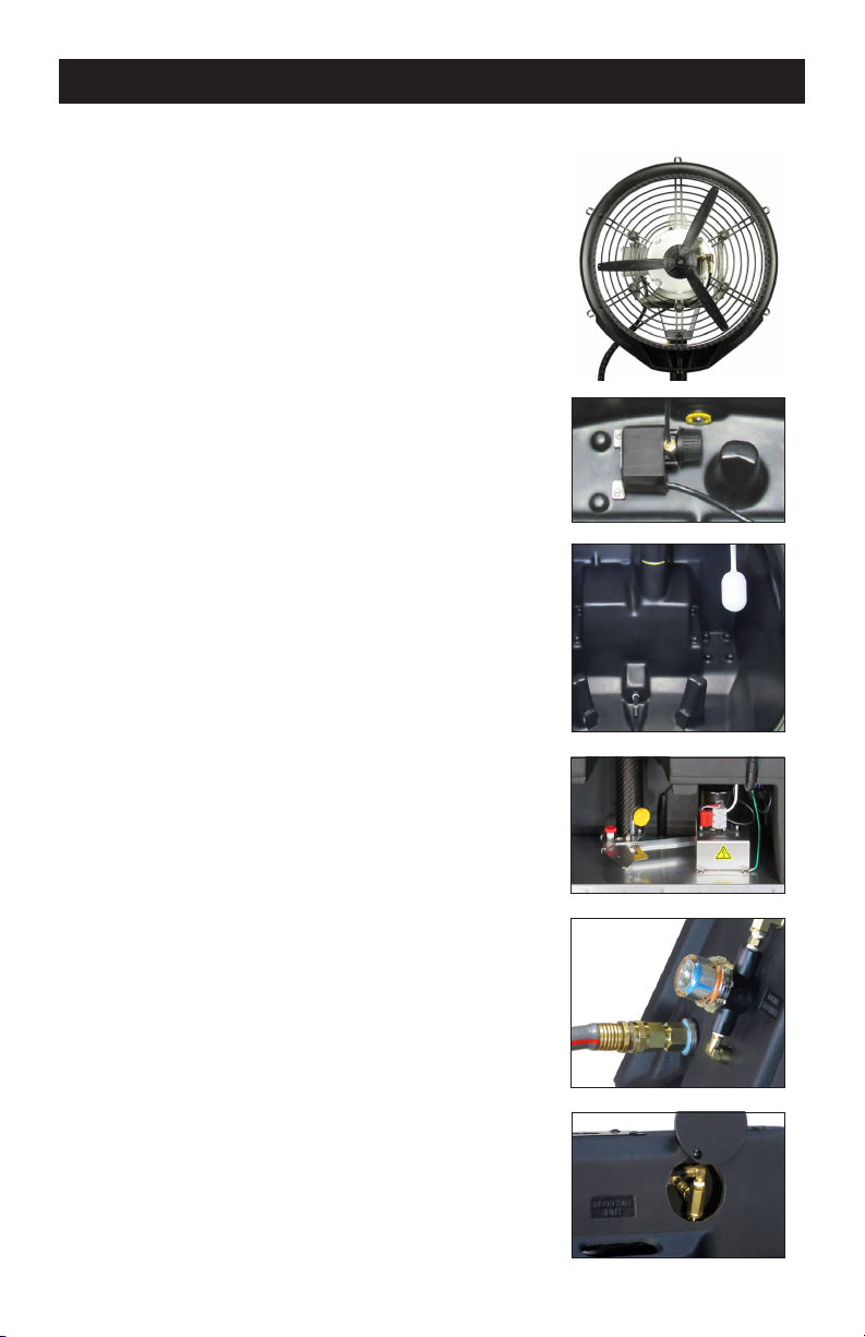
If there is a lot of calcium build-up near the end of your atomizing fan blades.
Remove and clean by soaking the blade assembly in bath of (CLR) calcium
dissolving solution.
Check the sweep switch, also check the oscillator motor.
This indicates a bad oat valve. Check, service or replace.
This mode requires water in the tank to activate the uid level switch. If still
not working, test the uid level switch and replace if needed.
If any deep scratches or dents occurs where the drain plug seals against the
tanks wall, this can cause leaking. Attempt to smooth the walls of the hole
with sandpaper. Check the plug for any damage or cracked seals.
If there is a persistent plumbing leak. Use both thread tape (rst) with some
pipe sealant on top of tape to ensure a leak-proof connection.
If motor makes squeaky noise, smells and gets excessively hot. These are
signs of a motor going bad. Replace motor early to avoid future issues.
Check power supply and power cord. Check inside control box for loose
connections. Consult an electrician or replace the control box assembly.
Turn off all other devices connected to the same circuit. If the breaker
continues to trip, the fan motor is probably bad and in need of repair.
Consult an electrician for professional evaluation.
6
WARNING! BEFORE
INSPECTION AND/OR SERVICE
DISCONNECT AND LOCK OUT
POWER SOURCE

SERVICE & REPAIR
Fan Motor/Venturi/Blade
If you need to replace the fan motor, fan blade
or pinned venturi. Use a 5/32” allen wrench to
remove the housing. The blade can be removed
using a 3/32” allen wrench and the venturi can
be removed using a #2 phillips screwdriver.
Pump Service/Replacement
Unscrew and clean the pump’s sediment lter
about twice a year. To replace the pump, un-wire
the pump from inside the control box. Disconnect
the 1/4” tubing and remove two 7/16” nuts to
lift the pump out along with the stainless steel
bracket. Re-attach components to the new pump
and install in reverse sequence.
Float Valve & Fluid Level Switch
If replacing either part. Make sure to use thread
tape in addition to pipe sealant to ensure a leak-
proof connection.
Oscillator
If replacing an oscillator motor or a major
component. It’s best to remove the entire
oscillator assembly and complete the task on a
work bench. To remove the assembly: Un-wire
the motor, remove the carbon ber column, and
unbolt the four 5/16-18 bolts underneath the
stainless steel base plate.
Strainer
Inspect and/or clean the in-line strainer a few
times a year. The clear cover unscrews counter-
clockwise (usually) by hand.
Service (peep hole)
If the atomizing fan head needs to be removed
from the tank. The fans plumbing connection is
accessible through the service (peep hole). This
service hole is also convenient for other plumbing
service procedures.
7

ELECTRICAL SCHEMATICS
CoolAire Electrical Schematic
115 VAC 60 Hz 1 Ph
115V
osc
motor
oscillator
locking switch
osc
light
115 VAC
LINE
DPST
contactor
30A
N
Y
uid level
switch
rotary mode
switch
DPDT
25A (L)
115V
feed
pump
FAN
motor
115 Volt
auto shut-off
momentary switch
Y
shut-off
mode
light
pump
locking switch
pump
light
Pole #1 - NO
Pole #2 - NO
ON
light
1
3
5
2
4
6
Double Pole
Contactor
detail
Load In
Load Out
coil
N
coil
115 VAC
Load
ON
AUTO
Shut-off
2, 4, 5 1, 3, 8
65
3
1
24
CoolAire Electrical Schematic
230 VAC 50 Hz 1 Ph
230V
osc
motor
oscillator
locking switch
osc
light
230 VAC
LINE
DPST
contactor
30A
N
Y
uid level
switch
rotary mode
switch
DPDT
25A (L)
230V
feed
pump
FAN
motor
230 Volt
auto shut-off
momentary switch
Y
shut-off
mode
light
pump
locking switch
pump
light
Pole #1 - NO
Pole #2 - NO
ON
light
1
3
5
2
4
6
Double Pole
Contactor
detail
Load In
Load Out
coil
N
coil
230 VAC
Load
ON
AUTO
Shut-off
4, 5 1
65
3
1
24
3, 8, 2
115V 60Hz 1Ph 230V 50Hz 1Ph (Foreign)
8

REPLACEMENT PARTS - IDENTIFICATION
Atomizing Fan Head Parts Part No.
Fan Motor 13-500
Venturi 14
Fan Blade 531
Drain Tube 44
Fan Housing (prepped) 502-CP
Housing Hand-Hold Handle 821
Oscillator Parts Part No.
Oscillator Motor (115V) 741
Oscillator Motor (230V) 741-230
Osc. Sweep Thumb Screw 822
Osc. Control SST Cover 736
Osc. Cover Turn Knob Lock 742
Plumbing Parts Part No.
Pump (115V) 100
Pump (230V) 101
Float Valve 721
In-line Strainer 748
1/4 Turn Ball Valve 400-016
SST Flow Restrictor Tube 823
Drain Plug 793
Tank Parts Part No.
Push Handle (Carbon Fiber) 824
Tank Lid 825
Tank (prepped w/ holes) 749-P
Service (Peep-Hole) Cover 826
Front Wheels w/Locks 715
Rear Wheels 716
Other Electrical Part No.
Fluid Level Switch 827
Elect. Control Box Assy. 828
Power Cord 507
Other Misc. Parts Part No.
Column (Carbon Fiber) 745
Thumb Screws (Column) 829
9
Atomizing Fan Head
Oscillator Parts
Plumbing
Parts
Tank
Parts
Pump
Column
Float Valve
Control Box
Push
Handle
Fluid Level
Switch
Service Cover &
Flow Restrictor Tube

Aquafog, CoolAire and accessories are warranted to the original
purchaser against defects in material and workmanship under normal
use for one full year from date of purchase. Any part determined to be
defective and returned to the manufacturer, shipping cost prepaid, will be
repaired or replaced at Jaybird Manufacturing, Inc.'s discretion without
charge. Proof of purchase date and an explanation of the problem or
complaint must accompany the returned portion of the machine.
Jaybird Manufacturing, Inc. reserves the right to verify the legiti-
macy of claimed defects. The provisions of this warranty do not apply to
damage resulting from direct or indirect misuse, negligence, accident,
lack of maintenance, or unauthorized repairs or alterations which affect
the machine's performance or reliability.
LIMITATIONS OF LIABILITY. TO THE EXTENT ALLOWABLE UNDER
APPLICABLE LAW, JAYBIRD MANUFACTURING, INC.'S LIABILITY FOR
DEATH, INJURIES TO PERSONS OR PROPERTY, OR FOR CONSEQUENTIAL
OR INCIDENTAL DAMAGES ARISING FROM THE USE OF OUR EQUIP-
MENT IS EXPRESSLY DISCLAIMED. JAYBIRD MANUFACTURING, INC.'S
LIABILITY IN ALL EVENTS IS LIMITED TO, AND SHALL NOT EXCEED,
THE PURCHASE PRICE PAID. NO OTHER WARRANTY, EXPRESSED OR
IMPLIED, IS AUTHORIZED, INCLUDING WARRANTIES OF MERCHANT-
ABILITY AND FITNESS FOR A PARTICULAR PURPOSE.
This warranty gives you specic legal rights, and you may also have other
rights, which vary from state to state.
1
year
ONE YEAR LIMITED WARRANTY
Made in U.S.A.
© 2024 Jaybird Mfg., Inc.
Jaybird Manufacturing, Inc.
135 Summer Lane
Centre Hall, PA 16828
Parts & Service: 1.814.364.1800
Website: www.jaybird-mfg.com
This manual suits for next models
1
Table of contents