ENGLISH OPERATION MANUAL
JB SYSTEMS®2/6 LED DIAMOND II
To protect the environment, please try to recycle the packing material as much as possible.
To prevent fire or shock hazard, do not expose this appliance to rain or moisture.
To avoid condensation to be formed inside, allow the unit to adapt to the surrounding temperatures when
bringing it into a warm room after transport. Condense sometimes prevents the unit from working at full
performance or may even cause damages.
This unit is for indoor use only.
Don’t place metal objects or spill liquid inside the unit. Electric shock or malfunction may result. If a foreign
object enters the unit, immediately disconnect the mains power.
Locate the fixture in a well ventilated spot, away from any flammable materials and/or liquids. The fixture
must be fixed at least 10cm from surrounding walls.
Don’t cover any ventilation openings as this may result in overheating.
Prevent use in dusty environments and clean the unit regularly.
Keep the unit away from children.
Inexperienced persons should not operate this device.
Maximum safe ambient temperature is 30°C. Don’t use this unit at higher ambient temperatures.
Make sure the area below the installation place is free from unwanted persons during rigging, de-rigging
and servicing.
Always unplug the unit when it is not used for a longer time or before to start servicing.
The electrical installation should be carried out by qualified personal only, according to the regulations for
electrical and mechanical safety in your country.
Check that the available voltage is not higher than the one stated on the unit.
The power cord should always be in perfect condition. Switch the unit immediately off when the power cord
is squashed or damaged. It must be replaced by the manufacturer, its service agent or similarly qualified
persons in order to avoid a hazard.
Never let the power-cord come into contact with other cables!
This fixture must be earthed in order to comply with safety regulations.
Don’t connect the unit to any dimmer pack.
Always use an appropriate and certified safety cable when installing the unit.
In order to prevent electric shock, do not open the cover. There are no user serviceable parts inside.
Never repair a fuse or bypass the fuse holder. Always replace a damaged fuse with a fuse of the same
type and electrical specifications!
In the event of serious operating problems, stop using the fixture and contact your dealer immediately.
The housing and the lenses must be replaced if they are visibly damaged.
Please use the original packing when the device is to be transported.
Due to safety reasons it is prohibited to make unauthorized modifications to the unit.
Important: Never look directly into the light source! Don’t use the effect in the presence of persons suffering
from epilepsy.
DESCRIPTION:
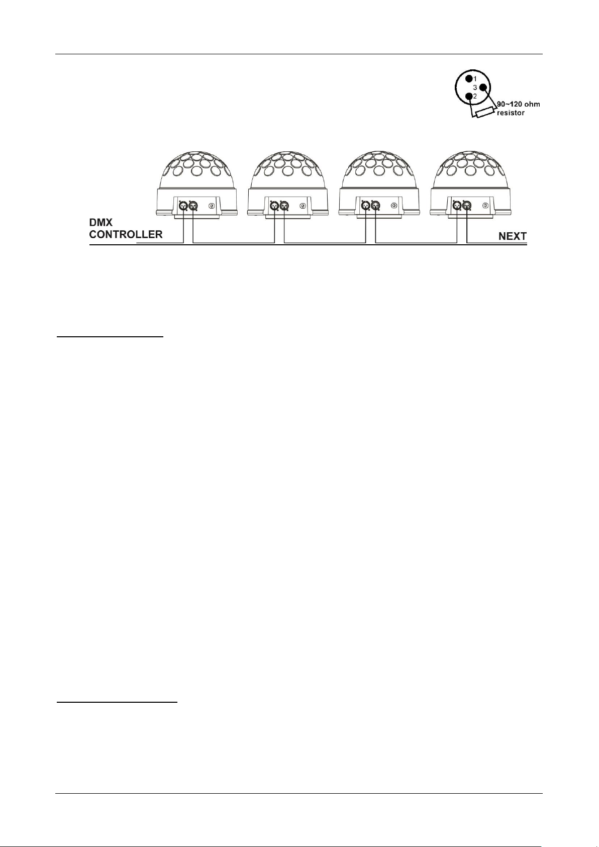
1. DMX input
2. DMX output
3. Mains Cable: connect this cable to the mains.
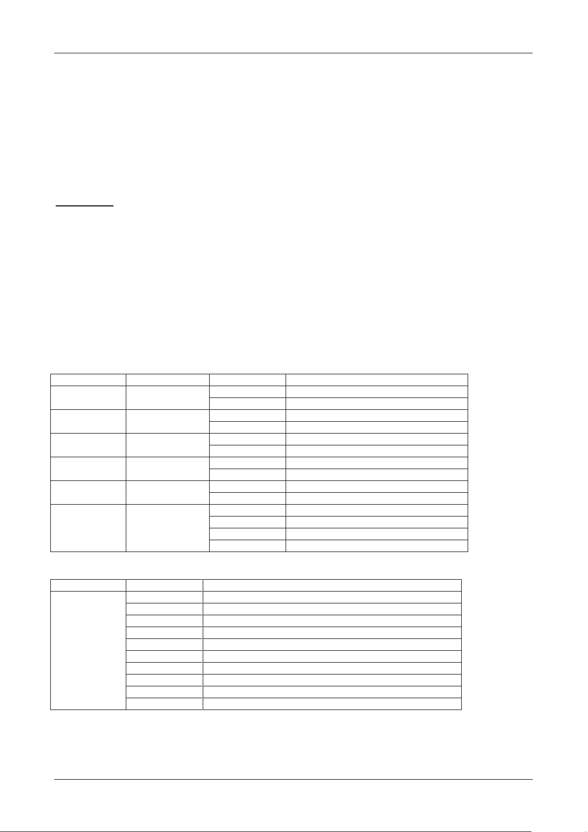
4. MENU button: Used to scroll the different working
modes.
5. UP button: Used to select a higher speed or DMX
address. See chapter “how to use the unit” for
more information.
6. DOWN button: Used to select a lower speed or
DMX address. See chapter “how to use the unit”
for more information.
7. ENTER button: used to confirm your selection.
CAUTION: Do not stare at operating lamp.
May be harmful to the eyes.