jbc FAE2-5A User manual

INSTRUCTION MANUAL
Fume Extractor
Ref. FAE2-5A
www.jbctools.com

INSTRUCTION MANUAL
Compact Filter + Pre-filter ................... 1 unit
Ref. FAE2-100
*Already assembled
Packing List
The following items should be included:
Fume Extractor ......................................... 1 unit
Ref. FAE2-5A
Cleaning stick ............................................ 1 unit
Ref. 0004009
Manual ........................................................... 1 unit
Ref. 0018826
Power cable ................................................ 1 unit
Ref. 0009417 (100V / 120V)
0009401 (230V)
RJ12 direct cable .................................... 2 units
Ref. 0019751
2
Fume Extractor
Ref. FAE2-5A
www.jbctools.com

Features
Aspiration tube for up to 4 stands (2 work
intakes configuration) or for 1 workbench
(4 work intakes configuration).
Aspiration
tubes for
workbenchs
Wheels and brake
system to move
around easily
Filter saturation
indicator
Connections ports
Quick release
lever for filter
change
Power socket
Main switch
Process screen
Aspiration tube for up to 4 stands (2 work
intakes configuration) or for 1 workbench
(4 work intakes configuration).
www.jbctools.com
3

Features
Pre-filter
Re f. FAE 2-110
Compact filter + Pre-filter
Ref. FAE 2-10 0
Important:
Before using, unseal
the filter and remove the
bottom protection of the
compact filter.
4

Visit www.jbctools.com
for further details.
Fume Extractor
Ref. FAE2-5A
Accessories for
stand aspiration
(up to 4 stands)
Ref. FAE040
To be assembled on
your workbench with
the included clamp
Ref. FAE030
To be assembled directly
on your workbench (hole
drilling required)
Stand
Aspiration Ducts
Ref. FAE050
For modular stands
(From SD versions
onwards)
Ref. FAE060
For compact stations
(From B versions
onwards)
Flexible arms Ø50
Ref. FAE070
Lenght: 1 m (39.37 in)
To be assembled on
your workbench with
the included clamp
Ref. FAE020
To be assembled directly
on your workbench
(hole drilling required)
Flexible Hoses Ø50
Ref. FAE010
Lenght: 1,5 m
(59.05 in)
Connect the Fume
Extractor to the flexible
arm or to the accessory
for stand aspiration
Assembly for 2 work intakes configuration (default configuration)
For a basic working system you need:
www.jbctools.com
5

Flexible Hoses Ø50
Ref. FAE010
Lenght: 1,5 m
(59.05 in)
Connect the Fume
Extractor to the flexible arm
Visit www.jbctools.com
for further details.
Fume Extractor
Ref. FAE2-5A
Assembly for 4 work intakes configuration (optional configuration)
In this configuration aspiration at stand is not available, aspiration flow is set High. Note that in this
configuration, suction force per intake is decreased when compared to 2 work intakes configuration.
See details on page 16. For a basic working system you need:
Flexible arms Ø50
Ref. FAE070
Lenght: 1 m (39.37 in)
To be assembled on
your workbench with
the included clamp
Ref. FAE020
To be assembled directly
on your workbench
(hole drilling required)
6

Communication ports
RJ12 connections take precedence over USB connections. The fume extractor will only attend RJ12
port.
Connection with Excellence range
Connect up to 2 stations directly to the fume extractor using RJ12 ports.
For a correct operation always update the soldering stations with the latest software version available.
The minimum required version is number 8886160 for DDE, HDE & NAE stations and number
8886162 for DME stations.
For 2 work intakes configuration, when two stations are connected to the fume extractor, each station
controls the extraction port to which it is connected. Every tool connected to the soldering station
need to be asigned to an available fume extraction port through the Peripherals menu of the station.
For 4 work intakes configuration, when two stations are connected to the fume extractor, the station
connected to port1 controls extraction ports 1 and 2, whereas station connected to port2 control
extraction ports 3 and 4. Every tool connected to the soldering station need to be asigned to an
available fume extraction port through the Peripherals menu of the station.
station 1 station 2
www.jbctools.com
7

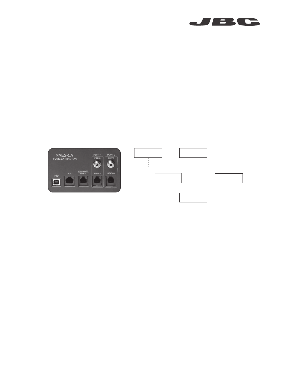
Aspiration ports control
For 2 work intakes configuration:
If only 1 station is connected to Port1, the
station will detect the 2 work intakes identified
as FAE_a (work1) and FAE_b (work2).
For 4 work intakes configuration:
If only 1 station is connected to Port1, the
station will detect the 4 work intakes identified
as FAE_a (work1), FAE_b (work2), FAE_c
(work3) and FAE_d (work4).
For 2 work intakes configuration:
If 1 station is connected to Port2, the station
will only detect the work2 intake identified as
FAE_a.
For 4 work intakes configuration:
If 1 station is connected to Port2, the station
will detect the 2 last work intakes identified as
FAE_a (work3) and FAE_b (work4).
The pedal connection takes precendence
over the RJ12 connection, the equipment
will only attend the Pedal port.
For 2 work intakes configuration:
When 2 stations are connected to Port1 and Port2, work intakes 1 and 2 are both detected as FAE_a
in the Peripherals menu of soldering stations.
For 4 work intakes configuration:
When 2 stations are connected to Port1 and Port2, work intakes 1 and 3 are detected as FAE_a and
work intakes 2 and 4 as FAE_b in the Peripherals menu of soldering stations.
8

Connection with QSC-A
QSC-A makes possible connecting as many JBC Stations1,2 as desired to the fume extractor FAE,
through the USB interface (USB A-B cables required).
The software inside the QSC makes easy configuring which of the 2 fume extractor ports will be
opened when picking up any tool from its stand.
You can configure the FAE directly on the QSC (requires a HDMI connected to a screen, a keyboard
and a mouse) or from any computer in the same LAN as the QSC (connected by Wifi or Ethernet) by
tipping the address in a Web Browser (see page 17).
1JBC stations featuring USB connectors are supported except for JT-D, TE-D and older hot air
stations. PHB/PHS preheaters and older are not supported.
2Fume extraction on the stand is limited to 8 tools for 2 work intakes configuration.
QSC-A
station 1
station 3
station 2
station 4
USB A/B cable
www.jbctools.com
9

Working modes
Autonomous
Pedal
Activate the vacuum system with the pedal without being connected to a JBC station.
For 2 work intakes configuration, each pedal control its associated port, whereas for 4
intakes configuration, pedal port1 controls work1 and work2 intakes and pedal port2
controls work3 and work4 intakes.
Continuous mode
The fume extractor works in continuous mode with the four valves opened.
Remote
QSC-A
The valve in the working area opens when the tool is lifted from the stand. Once the tool
is returned to the stand and enters sleep mode, the valve in the work area closes and the
stand valve opens. Stand extraction is not available for 4 work intakes configuration.
Station
The valve in the working area opens when the tool is lifted from the stand. Once the tool
is returned to the stand and enters sleep mode, the valve in the work area closes and the
stand valve opens. After a period of inactivity on both ports, the unit stops. Stand extraction
is not available for 4 work intakes configuration.
10

Port 1
W
0:05
S
1:00
Port 2
W
ON
S
OFF
Flow
Saturation 20% 100%
Port 1
W
0:05
S
1:00
Port 2
W
ON
S
OFF
Flow
HML
Filter
Carbon life 90%
Saturation 20%
Filter
Carbon life 90%
Saturation Carbon life
20% 90%
W1
ON
W2
ON
W3
ON
W4
ON
Main screen for 4 intakes configuration
Aspiration ports
intakes status
Aspiration
program
Stand intakes
status
Work intakes
status
High, medium
and low
Control Process
Main Screen for 2 intakes configuration
Work intakes
status
www.jbctools.com
11

4 Filter set
5 Counters
6 Program version
Main menu
Exit
1 Reset
2
Unit
3
Port
Unit
1 Continuous mode OFF
2
Beep ON
3 PIN OFF
4 Change PIN
Back
5
Pedal port 2
Port
1 Program Ctm - 100%
2
Delay port 1
3
Delay port 2
4 Pedal port 1
Filter set
1 Carbon life 90%
2 Saturation 20%
3 Reset carbon
Back
Counters
1 Total
2 Partial
Back
Port
1 Delay port 1
2 Delay port 2
3 Delay port 3
4 Delay port 4
5
Pedal ports 1 and 2
6
Pedal ports 3 and 4
Back
Back
5 Work intakes 2
Control Process
Main Menu
Original Pin: 0105
For 2 work intakes configuration
For 4 work intakes configuration
12

Unit
1 Continuous mode OFF
2
Beep ON
3 PIN OFF
4 Change PIN
Back
5 Work intakes 2
It opens all aspiration intakes
with the selected program
(high, medium, low or custom).
When option 4 is selected,
the 4 intakes wil work as
workbench extraction
(extraction in the stand is not
available).
Control Process
Unit Screen
www.jbctools.com
13

Delay to stop port 1
1 Work area 5 sec
2 Stand 30 sec
Back
Pedal port 1
1 Activation One-touch
2 Mode Pressed
Back
Delay to stop port 1
1 Work area 5 sec
2 Stand 30 sec
Back
Pedal port 1
1 Activation One-touch
2 Mode Pressed
Back
Port
1 Program Ctm - 100%
2
Delay pt 1
3
Delay port 2
4 Pedal port 1
Custom
Port
1 Program Ctm - 100%
2
Delay port 1
3
Delay port 2
4 Pedal port 1
Back
5
Pedal port 2
Custom program
Select work area flow
80 %
Set the time that the
workbench valve remains
opened once the tool is
returned to stand (Range
0-300 seconds).
Selects the pedal action
mode (Options Pressed and
One-touch).
Set the time the stand valve
remains opened once the
tool is returned to the stand
(Range 0-999 seconds).
Selects how to detect the
pedal action (Options Pressed
and Released).
Selects between a Preset (High,
Medium, Low) and Custom
aspiration program.
Selects the suction flow rate
(Range %). Parameter available in
the Custom program. It can also
be changed from the main screen.
Control Process
Port Screen for 2 intakes configuration
14

Delay to stop port 1
1 Work area 5 sec
Back
Pedal port 1
1 Activation One-touch
2 Mode Pressed
Back
Pedal port 1 and 2
1 Activation One-touch
2 Mode Pressed
Back
Port
1 Delay port 1
2 Delay port 2
3 Delay port 3
4 Delay port 4
5
Pedal ports 1 and 2
6
Pedal ports 3 and 4
Back
Set the time that the
workbench valve remains
opened once the tool is
returned to stand (Range
0-300 seconds).
Selects the pedal action
mode (Options Pressed and
One-touch).
Selects how to detect the
pedal action (Options Pressed
and Released).
Control Process
Port Screen for 4 intakes configuration
www.jbctools.com
15

Fume extractor configurations
Some parameters, features and the performance vary depending on fume extractor configuration, see
the following table:
2 work intakes 4 work intakes
Work aspiration intakes 2 4
Stand aspiration intakes 2 Not available
Flow per work intake 76 m3 / h (44.73 cfm) 52 m3 / h (30.6 cfm)
Flow per stand intake 4 m3 / h (2.35 cfm) Not available
Preset aspiration programs 3 1
Custom aspiration programs 9 Not a available
Power consumption 400 500
16

Save your
configuration
Stations
2 work intakes configuration 4 work intakes configuration
Update the equipment software
Fume extractor can be updated by means of JBC Updater software. If you want to update the
equipment be aware there is no station connected to RJ12 connectors. If a station is connected by
means RJ12 port the update process will not start.
Settings
QSC-A FAE Configuration Screen
The software detects automatically if a fume extractor or any station is connected, showing a table as
the image. The user can easily select wich fume extractor ports will be activated every time a specific
port (tool) is activated.
Color green: The link is done by clicking over the highlighted table position. The user only need to
uncheck the box in orther to remove the link.
Color red: Stations and FAEs marked with red indicator correspond to not currently connected
equipment. Connections are saved in case that equipment is reconnected again in the future.
To save the configuration press “save” button.
www.jbctools.com
17

Maintenance - Filter replacement
- The unit notifies through both the display and
the LED when filters need maintenance.
- To replace the filters, first turn the fume
extractor off. Then remove the cover by
opening the quick release lever of the casing.
- If once the pre-filter has been changed the
saturation indicator is on, it means that the
compact filter is already saturated and must
be replaced too.
- The duration of the compact filter is 1 year
maximum once its packaging is opened.
- Once the compact filter has been replaced,
the filter counter must be reset.
(Main Menu > Filter set > Reset carbon)
- If the display shows an error when the
equipment is switched on, it is probable that
the cover and casing connectors are dirty
and making false contact. Remove the cover
again and clean both connectors.
- If the filter is changed while the fume extractor
is on, once the cover is placed the equipment
starts an automatic filter detection process: the
work valves open, the stand valves close and
the fume extractor suctions for a few seconds.
Important: Read the page 4 before using the fume extractor.
Pre-filter
Re f. FAE 2-110
Compact filter
+ Pre-filter
Ref. FAE 2-10 0
18

- Check the status of the valves when replacing the pre-filter or the compact filter.
- Use the cleaning stick if necessary and clean with alcohol to remove dirt residues.
Latch Adjustment
- The locking force between casing and cover
can be adjusted by turning the knurled nut of
the locking mechanism.
- Turn clockwise to loosen and counterclockwise
to tighten.
Clean the disc
and the gasket
on both sides
Intake valve
Ref. 0018831
Maintenance - Valves
Read safety guidelines to do the equipment maintenance securely.
www.jbctools.com
19

Safety
- The equipment is only designed to filtrate the fumes generated by soldering.
- Do not use the units for the filtration of combustible, explosive or corrosive gasses.
Incorrect use may cause fire.
- The power cord must be plugged into approved bases. Be sure that it is properly grounded
before use. When unplugging it, hold the plug, not the wire.
- Do not work on electrically live parts.
- Do not leave the appliance unattended when it is on.
- Do not cover the ventilation grills. Heat can cause inflamable products to ignite.
- Avoid flux coming into contact with skin or eyes to prevent irritation.
- This appliance can be used by children over the age of eight and persons with reduced
capabilities or lack of experience provided that they have been given adequate supervision or
instruction concerning use of the appliance and understand the hazards involved.
- Maintenance must not be carried out by children unless supervised.
- Keep your workplace clean and tidy. Wear appropriate protective mask, glasses and gloves when
handling dirt filter or pre-filter.
- The quick release levers of the casing are only for handling the cover, not the complete equipment.
- Do not use the equipment without the filters.
- Saturated filters can not be cleaned and reused.
- Avoid blowing the filter or the dirty parts of the equipment, if necessary it is advisable to vacuum.
- Avoid losing particles in the filter during handling it.
- Treat the saturated filters as waste depending on the filtered contaminant and the applicable
standars in each country. This is the European Waste Catalog classification:
15 02: Absorbents, filter materials, wiping cloths and protective clothing.
15 02 02: Absorbents, filter materials (including oil filters not otherwise specified, wiping cloths,
protective clothing contaminated by dangerous substances.
15 02 03: Absorbents, filter materials, wiping cloths and protective clothing.
- In case of not complying with the filter change recommendations, the maximum particle and gas
concentrations established in each country could be exceeded.
Follow safety guidelines to prevent electric shock, injury, fire or explosion.
20
Other manuals for FAE2-5A
1
Table of contents
Other jbc Ventilation Hood manuals
Popular Ventilation Hood manuals by other brands

Morgan
Morgan MDH-996MHC user manual

ROBINHOOD
ROBINHOOD RIJ3CL9BK Installation and operating instructions

KOJA
KOJA HiFEK 18 Installation, operation and maintenance guide

elvita
elvita CHF5780S quick start guide

Miele
Miele DA 210-3 Operating and installation instructions

Miele
Miele AB 45 installation instructions