jbc FAE2 User manual

FAE2
Fume Extractor for 2 Workbenches
INSTRUCTION MANUAL

Filter for FAE2 ..................................... 1 unit
Ref. FAE2-100 (already assembled)
Fume Extractor for 2 Workbenches ...1 unit
Cleaning Stick ............ 1 unit
Ref. 0004009
Manual ........................ 1 unit
Ref. 0028160
Power Cable ................ 1 unit
Ref. 0023715 (100V/120V)
0023714 (230V)
Premium Station
Cable (RJ12) ............. 2 units
Ref. 0019751
Compact Station Adapter
(RJ12 to USB A) ......... 2 units
Ref. 0023504
Compact Station Cable
(USB A/B) ................... 2 units
Ref. 0021042
The following items are included:
Packing List
This manual corresponds to the following references:
FAE2-5B (100V/120V/230V)
Pre-Filter
Compact
Filter
Unseal the filter and remove its bottom
protection before its first use
2

Features and Connections
Intakes for:
-Stand aspiraction (default) or
-Flexible Arm aspiration (4 Workbenches Mode)
Intakes for:
-Flexible arm aspiration
Wheels and Brake
System to move
around easily
Filter Saturation Indicator
-Green: Filter OK
-Yellow: ≤ 20% carbon lifetime or about to saturate
-Red: End of carbon lifetime or filter saturated
Quick Release
Lever for Filter
Replacement
Power Socket
Main Switch
Process Screen
Pedal Connections
RJ12 Premium Station Connections
USB-B Compact Station Connection
3
40 mm
50 mm
60 mm
80 mm
100 mm
130 mm 130 mm
para manuales - color gris
200 mm
300 mm

Port 1
WW
0:05
SS
1:00
Port 2
WW
ON
SS
OFF
FlowFlow
Saturation 20% 100%
FilterFilter
Carbon life 90%
Port 1
WW
0:05
SS
1:00
Port 2
WW
ON
SS
OFF
FlowFlow
HML
Saturation 20%
FilterFilter
Carbon life 90%
Fume Extractor
Ref. FAE2-5B
Accessories for
Stand Aspiration
(up to 4 stands)
Ref. FAE040
To be assembled on
your workbench with
the included clamp
Ref. FAE030
To be assembled directly on
your workbench (hole drilling
required)
Stand
Aspiration Ducts
Ref. FAE050
For modular stands
(From SD versions
onwards)
Ref. FAE060
For compact stations
(From B versions
onwards)
Flexible Arms Ø50
Ref. FAE070
Lenght: 1 m / 39.37 in
To be assembled on
your workbench with
the included clamp
Ref. FAE020
Lenght: 1 m / 39.37 in
To be assembled directly
on your workbench
(hole drilling required)
Flexible Hoses Ø50
Ref. FAE010
Lenght: 1,5 m / 59.05 in
Connect the Fume Extractor
to the flexible arm or to the
accessory
for stand aspiration
2 Workbenches Configuration (default)
Flow rate
High, medium
and low preset
aspiration
programs
Flexible arm aspiration
flow status
(work aspiration)
Stand aspiration
flow status
Main Screen
Preset program screen Custom program screen
Assembly Options
Access by and to change the aspiration program.
4

Saturation Carbon life
20% 90%
W1W1
ON
W2W2
ON
W3W3
ON
W4W4
ON
Flexible Hoses Ø50
Ref. FAE010
Lenght: 1,5 m
(59.05 in)
Connect the Fume
Extractor to the flexible arm
Fume Extractor
Ref. FAE2-5B
4 Workbenches Configuration (optional)
Flexible Arms Ø50
Ref. FAE070
Lenght: 1 m (39.37 in)
To be assembled on
your workbench with
the included clamp
Ref. FAE020
To be assembled directly
on your workbench
(hole drilling required)
Main Screen
Aspiration intake status
(work intake)
In order to set this
configuration, change
workbench parameter to 4
(see page 7).
In this configuration stand
aspiration is not available.
Aspiration flow is set to high
level.
Note: Suction force per intake
decreases compared to “2
workbenches configuration“
(see page 14).
5
40 mm
50 mm
60 mm
80 mm
100 mm
130 mm 130 mm
para manuales - color gris
200 mm
300 mm

17:14
Peripherals Port 1-T245
Pedal None
Module None
Fume extractor FAE_a
Back
Peripherals Menu
Premium Station
Cable
Connect up to 4 stations directly to a fume extractor through the soldering station robot port. Every
tool connected to a station can control the aspiration system.
Each Station detects the fume extractor as “FAE_a”. The tool that should activate the fume extraction
need to be configured through the peripheral menu option on the station menu.
Note: For a correct operation always update soldering stations with the latest available software
version. The minimum required version is 8886160 for DDE, HDE and NAE stations and 8886162 for
DME stations.
Station Connections for Premium Range
JBC Soldering Stations feature a robot port to the fume extractor in order to automatically activate
the extraction when the tools are in use. Use the Premium Station Cable (included) for the connection.
6

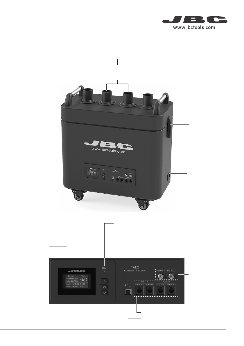
For 2 Workbenches Configuration:
Stations (Excellence or Advanced range) connected to RJ12 connectors station1 and station2 can
control flexible arm1/stand1 aspiration intakes, whereas those which are connected to station3 and
station4 can control flexible arm2/stand2 aspiration intakes.
For 4 Workbenches Configuration:
Each station connected to RJ12 connector stationX can control flexible armX aspiration intake (e.g.
station2 controls aspiration arm2).
Continuous mode
When continuous mode is enabled the 4 aspiration intakes are opened and fume extractor suction is
activated. Aspiration remains active until continuous mode is disabled or the equipment is powered
off. (See details on page 9).
Station Connections for Compact Range
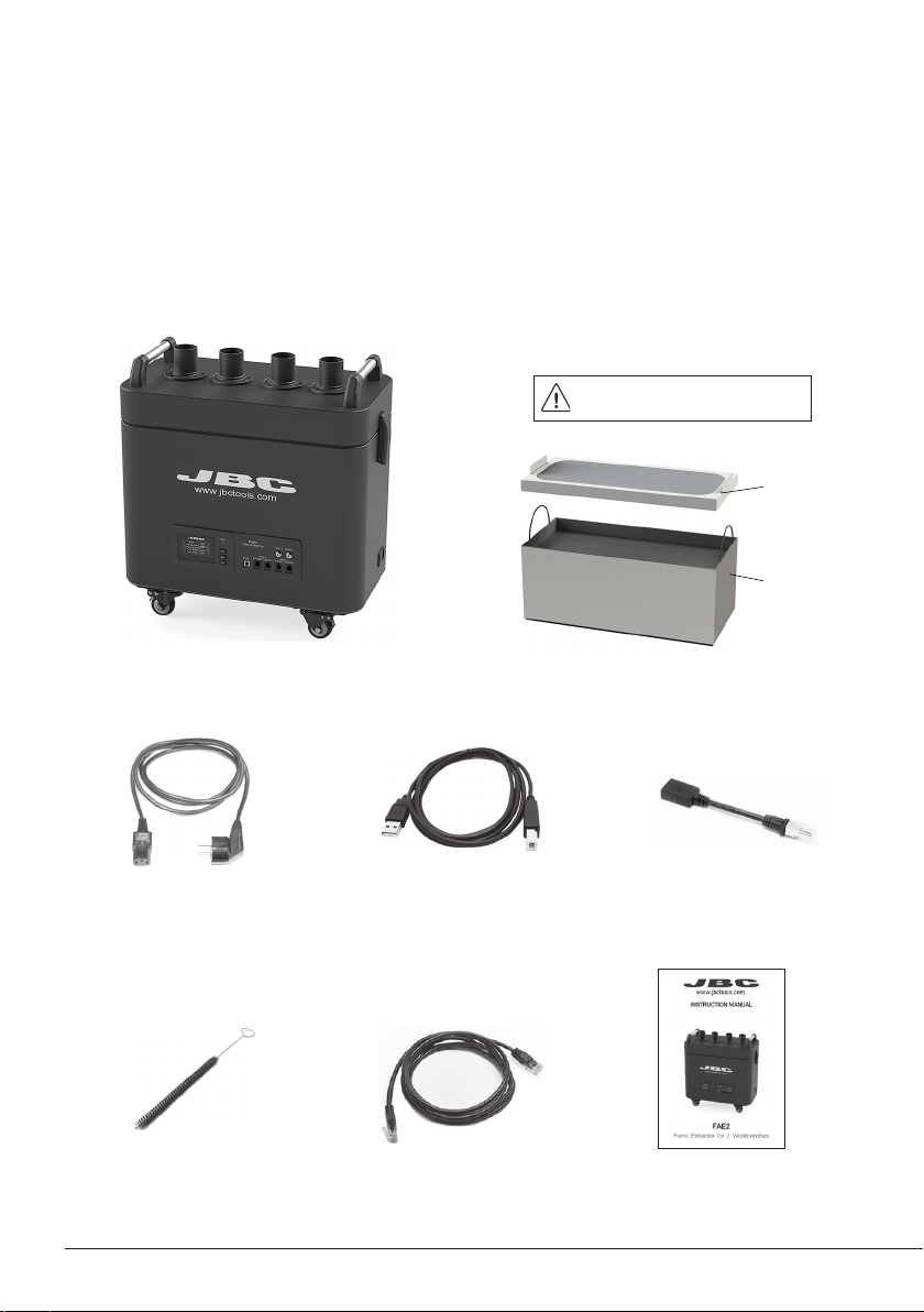
Use the Compact Station Cable and the Adapter cable to connect JBC Soldering Stations. They
feature a USB-B port to the fume extractor in order to automatically activate the extraction when the
tools are in use.
Compact Station
Cable + Adapter
Equipment Software Update
JBC Updater
The fume extractor can be updated via the USB-B connection by means of JBC Updater software.
Download software from: www.jbctools.com/software.html.
Note: For the updating process the Premium Station Cable (RJ12) has to be disconnected. If a station
is connected to RJ12 connector the update process will not start.
CD-S
CD-B
CA
CS
CDE-S
CDE-B
CP
OK
TOOL
EARTHING FUSE
AUX
USE ONLYWITH A 250 V FUSE
OK
ºC
ºF
A
OK
Language
Mode
Exit
Language
Mode
Exit
Language
Mode
Exit
Maximum temp
Minimum temp 200ºC
350ºC
8886698
PIN
Sound
Date&Time
02/06/2021, 15:01
ºC
On
O
Red limit 40%
0.5s/div
Ok to reset soldering Ref.
20
16
12
8
4
355
350
345
340
335
180
Sleep
W% ºC
Time
Energy
C245907 Ref.
2.3s
14W·s
---
---
ºC
19:29
Selected
Min 200 Max 400
350
º
C
0.5s/div
Ok to reset soldering Ref.
20
16
12
8
4
355
350
345
340
335
180
Sleep
W% ºC
Time
Energy
C210009 Ref.
2.3s
14W·s
---
---
ºC
19:29
Selected
Min 200 Max 400
350
º
C
0.5s/div
Ok to set up soldering Ref.
20
16
12
8
4
355
350
345
340
335
350
Sel. temp. 350ºC
W% ºC
Time
Energy
C245907 Ref.
2.3s
14W·s
---
---
ºC
19:29
0.5s/div
Ok to set up soldering Ref.
20
16
12
8
4
355
350
345
340
335
350
Sel. temp. 350ºC
W% ºC
Time
Energy
C210009 Ref.
2.3s
14W·s
---
---
ºC
19:29
0.5s/div
Ok to reset soldering Ref.
20
16
12
8
4
355
350
345
340
335
350
Sel. temp. 350ºC
W% ºC
Time
Energy
C245907 Ref.
2.3s
14W·s
2.4s
13W·s
ºC
95%
0.5s/div
Ok to reset soldering Ref.
20
16
12
8
4
355
350
345
340
335
350
Sel. temp. 350ºC
W% ºC
Time
Energy
C210009 Ref.
2.2s
18W·s
2.4s
17W·s
ºC
94%
0.5s/div
Ok to reset soldering Ref.
20
16
12
8
4
355
350
345
340
335
350
Sel. temp. 350ºC
W% ºC
Time
Energy
C245907 Ref.
2.3s
14W·s
---
---
ºC
19:29
0.5s/div
Ok to reset soldering Ref.
20
16
12
8
4
355
350
345
340
335
350
Sel. temp. 350ºC
W% ºC
Time
Energy
C245907 Ref.
2.3s
14W·s
1.3s
8W·s
ºC
38%
19:29
19:29
19:29
0.5s/div
Ok to reset soldering Ref.
20
16
12
8
4
355
350
345
340
335
350
Sel. temp. 350ºC
W% ºC
Time
Energy
C210009 Ref.
2.3s
14W·s
---
---
ºC
19:29
0.5s/div
Ok to reset soldering Ref.
20
16
12
8
4
355
350
345
340
335
350
Sel. temp. 350ºC
W% ºC
Time
Energy
C210009 Ref.
2.3s
14W·s
1.3s
8W·s
ºC
38%
19:29
1s/div
150 Time
C210-008 Ref. .
4.5s ---
ºC
SOLDERING JOINT INFO 1/3
Sel. temp.
Cartridge
Time
Max temp
Min temp
Energy
Result
Last Ref. Diff.
350ºC 350ºC
C245907
2.4s
350ºC
335ºC
13W·s
2.3s
C245907
-2%
350ºC +0%
340ºC -1%
14W·s +29%
95%
1s/div
150 Time
C210-008 Ref. .
4.5s ---
ºC
SOLDERING JOINT INFO 1/3
Sel. temp.
Cartridge
Time
Max temp
Min temp
Energy
Result
Last Ref. Diff.
350ºC 350ºC
C210009
2.4s
350ºC
335ºC
13W·s
2.3s
C210009
-2%
350ºC +0%
340ºC -1%
14W·s +29%
95%
C21
00
09
Cartridge
Language
Mode
Exit
Cartridge
Language
Mode
Exit
Hiberna�on
ºC
25% 75%
Power C245907
50%
19:29
325
º
CSel. temp.
325ºC
25% 75%
Power C245907
50%
Sleep
ºC
25% 75%
Power C245907
50%
19:2919:29
Hiberna�on
ºC
25% 75%
Power
50%
19:29
325
º
CSel. temp.
325ºC
25% 75%
Power
50%
Sleep
ºC
25% 75%
Power
50%
19:2919:29
CD-S
CD-B
CA
CS
CDE-S
CDE-B
CP
OK
TOOL
EARTHING FUSE
AUX
USE ONLY WITH A 250 V FUSE
OK
ºC
ºFA
OK
Language
Mode
Exit
Language
Mode
Exit
Language
Mode
Exit
Maximum temp
Minimum temp 200ºC
350ºC
8886698
PIN
Sound
Date&Time
02/06/2021, 15:01
ºC
On
O
Red limit 40%
0.5s/div
Ok to reset soldering Ref.
20
16
12
8
4
355
350
345
340
335
180
Sleep
W% ºC
Time
Energy
C245907 Ref.
2.3s
14W·s
---
---
ºC
19:29
Selected
Min 200 Max 400
350
º
C
0.5s/div
Ok to reset soldering Ref.
20
16
12
8
4
355
350
345
340
335
180
Sleep
W% ºC
Time
Energy
C210009 Ref.
2.3s
14W·s
---
---
ºC
19:29
Selected
Min 200 Max 400
350
º
C
0.5s/div
Ok to set up soldering Ref.
20
16
12
8
4
355
350
345
340
335
350
Sel. temp. 350ºC
W% ºC
Time
Energy
C245907 Ref.
2.3s
14W·s
---
---
ºC
19:29
0.5s/div
Ok to set up soldering Ref.
20
16
12
8
4
355
350
345
340
335
350
Sel. temp. 350ºC
W% ºC
Time
Energy
C210009 Ref.
2.3s
14W·s
---
---
ºC
19:29
0.5s/div
Ok to reset soldering Ref.
20
16
12
8
4
355
350
345
340
335
350
Sel. temp. 350ºC
W% ºC
Time
Energy
C245907 Ref.
2.3s
14W·s
2.4s
13W·s
ºC
95%
0.5s/div
Ok to reset soldering Ref.
20
16
12
8
4
355
350
345
340
335
350
Sel. temp. 350ºC
W% ºC
Time
Energy
C210009 Ref.
2.2s
18W·s
2.4s
17W·s
ºC
94%
0.5s/div
Ok to reset soldering Ref.
20
16
12
8
4
355
350
345
340
335
350
Sel. temp. 350ºC
W% ºC
Time
Energy
C245907 Ref.
2.3s
14W·s
---
---
ºC
19:29
0.5s/div
Ok to reset soldering Ref.
20
16
12
8
4
355
350
345
340
335
350
Sel. temp. 350ºC
W% ºC
Time
Energy
C245907 Ref.
2.3s
14W·s
1.3s
8W·s
ºC
38%
19:29
19:29
19:29
0.5s/div
Ok to reset soldering Ref.
20
16
12
8
4
355
350
345
340
335
350
Sel. temp. 350ºC
W% ºC
Time
Energy
C210009 Ref.
2.3s
14W·s
---
---
ºC
19:29
0.5s/div
Ok to reset soldering Ref.
20
16
12
8
4
355
350
345
340
335
350
Sel. temp. 350ºC
W% ºC
Time
Energy
C210009 Ref.
2.3s
14W·s
1.3s
8W·s
ºC
38%
19:29
1s/div
150 Time
C210-008 Ref..
4.5s ---
ºC
SOLDERING JOINT INFO 1/3
Sel. temp.
Cartridge
Time
Max temp
Min temp
Energy
Result
Last Ref. Diff.
350ºC 350ºC
C245907
2.4s
350ºC
335ºC
13W·s
2.3s
C245907
-2%
350ºC +0%
340ºC -1%
14W·s +29%
95%
1s/div
150 Time
C210-008 Ref..
4.5s ---
ºC
SOLDERING JOINT INFO 1/3
Sel. temp.
Cartridge
Time
Max temp
Min temp
Energy
Result
Last Ref. Diff.
350ºC 350ºC
C210009
2.4s
350ºC
335ºC
13W·s
2.3s
C210009
-2%
350ºC +0%
340ºC -1%
14W·s +29%
95%
C21
00
09
Cartridge
Language
Mode
Exit
Cartridge
Language
Mode
Exit
Hiberna�on
ºC
25% 75%
Power C245907
50%
19:29
325
º
CSel. temp.
325ºC
25% 75%
Power C245907
50%
Sleep
ºC
25% 75%
Power C245907
50%
19:2919:29
Hiberna�on
ºC
25% 75%
Power
50%
19:29
325
º
CSel. temp.
325ºC
25% 75%
Power
50%
Sleep
ºC
25% 75%
Power
50%
19:2919:29
JBC
Updater
Cable USB AB
7
40 mm
50 mm
60 mm
80 mm
100 mm
130 mm 130 mm
para manuales - color gris
200 mm
300 mm

Main menuMain menu
Exit
1 Reset
2
Unit
3
Port
4 Filter set
5 Counters
6 Program version
UnitUnit
1 Continuous mode OFF
2
Beep ON
3 PIN OFF
4 Change PIN
BackBack
5 Workbench 2
Filter setFilter set
1 Carbon life 90%
2 Saturation 20%
3 Reset carbon
BackBack
CountersCounters
1 Total
2 Partial
BackBack
BackBack
5
Pedal port 2
PortPort
1 Program Ctm - 100%
2
Delay port 1
3
Delay port 2
4 Pedal port 1
Total CountersTotal Counters
1 Plugged hrs 100
2 Idle hrs 10
3 Work area hrs 70
Port 1/2 OK >
4 Stand hrs 20
5 Work area cys 10
Port 1/2 OK >
BackBack
4 Stand hrs 20
5 Work area hrs 10
6 Reset
Port 1/2 OK >
BackBack
Partial CountersPartial Counters
1 Plugged hrs 100
2 Idle hrs 10
3 Work area hrs 70
Port 1/2 OK >
PortPort
1
Pedal ports 1 and 2
2
Pedal ports 3 and 4
BackBack
Menu Interface
Main Menu Parameters
Original Pin: 0105
2 workbenches configuration14 workbenches configuration2
Not available for
4 workbenches
configuration
8

PortPort
1 Program Ctm - 100%
2
Delay port 1
3
Delay port 2
4 Pedal port 1
BackBack
5
Pedal port 2
Delay to stop port 1Delay to stop port 1
1 Stand 30 sec
BackBack
Pedal port 1Pedal port 1
1 Activation One-touch
2 Mode Pressed
BackBack
PortPort
1 Program Ctm - 100%
2
Delay pt 1
3
Delay port 2
4 Pedal port 1
CustomCustom
Custom programCustom program
Select work area flow
80 %
PortPort
1
Pedal ports 1 and 2
2
Pedal ports 3 and 4
BackBack
Pedal port 1 and 2Pedal port 1 and 2
1 Activation One-touch
2 Mode Pressed
BackBack
Menu Interface
Port Menu for 2 Workbenches Configuration
OK
Port Menu for 4 Workbenches Configuration
9
40 mm
50 mm
60 mm
80 mm
100 mm
130 mm 130 mm
para manuales - color gris
200 mm
300 mm

Port 1
WW
OFF
SS
OFF
Port 2
WW
OFF
SS
OFF
FlowFlow
HML
Saturation 0%
FilterFilter
Carbon life 100%
STOPSTOP ##44
Cover opened or badly
closed. Double check the
cover.
STOPSTOP ##77
Valve STAND1 error.
Restart the unit, if the error
remains, replace the valve.
Fume Extractor Activation
Once the fume extractor is switched on, the display shows a similar screen as the following one and
the filter saturation indicator is green if the carbon lifetime is higher than 20%.
If the display shows STOP#4 or STOP#7, power off the fume extractor, remove the cover, place it back
and secure it using the quick release levers.
If the STOP#7 remains, replace the valve (ref. 0018831).
- Green: Filter OK
- Yellow: ≤ 20% carbon lifetime
or about to saturate
- Red: End of carbon lifetime
or filter saturated
10

Parameters
Important: Power off any station or device connected to the fume extractor before
modifying any parameter.
Unit
Parameter Description
Continuous mode
Enable/disable continuous aspiration. When enabled the 4 aspiration in-
takes are opened and fume extractor suction is activated. Aspiration re-
mains active until continuous mode is disabled or the equipment is powe-
red off.
By default Continuous mode is OFF.
Beep
Enable/disable the sound of the keypad.
By default Beep is ON.
PIN
Enable/disable PIN request when modifying parameters.
By default PIN is ON.
Change PIN
Change the default security PIN code.
By default the PIN is 0105.
Workbench
Select working mode for 2 or 4 workbenches.
By default workbench is 2.
11
40 mm
50 mm
60 mm
80 mm
100 mm
130 mm 130 mm
para manuales - color gris
200 mm
300 mm

Port
Parameter Description
Program
It sets the fume extractor aspiration flow. You can select between preset
and custom aspiration programs.
H (High), M (Medium) or L (Low) are the three preset options available.Use
up and down keys to switch between them while being on the main screen.
Up to ten aspiration levels between H (High) and L (Low) can be select for
custom program (range 10-100%). If a custom aspiration program is selec-
ted, the selected aspiration level can be changed on main the screen.
By default M (Medium) aspiration program is selected.
Delay to stop /
Stand
It sets the time that a fume extractor keeps aspirating fumes at the stand
once the tool is returned to it (range 0-999 seconds)
By default stand time is 60 seconds.
Pedal / Activation
It sets the pedal activation mode.
One-touch: Press the pedal once to activate aspiration. Press again to stop
aspiration.
Pressed: (Mode function must be pressed) aspiration is active as long as
the pedal is kept pressed.
By default activation is pressed.
Pedal / Mode
When the activation parameter is set to pressed, the mode parameter can
be configured to released mode. In this mode aspiration is always active
until the pedal is pressed.
By default mode is pressed.
12

Filter Set
Parameter Description
Carbon life
It shows remaining activated carbon lifetime expressed in %. It is also dis-
played on the main screen. When 0% is reached the system will show pop-
up message STOP#1 to replace the filter.
Saturation
It shows saturation status of HEPA + carbon filter set, expressed in
%. It is also displayed on the main screen. When 100% is reached
the system will show pop-up message STOP#2 to replace the filter.
Reset carbon
Perform this action after replacing the HEPA + carbon filter set. The
carbon lifetime counter will not start until the filter is detected for
the first time. After executing that function Carbon life will be 100%.
Extraction Control
Fume extractor aspiration may be controlled by:
Pedal Connection
By means of the pedal connection, fume extractor aspiration may be activated/deactivated by a
P-005/P-405 pedal. (See pedal activation modes on page 10)
13
40 mm
50 mm
60 mm
80 mm
100 mm
130 mm 130 mm
para manuales - color gris
200 mm
300 mm

Fume Extractor Configurations
Some parameters, features and the performance vary depending on fume extractor working mode,
see the following table:
Mode: 2 Workbenches Mode: 4 Workbenches
Flexible Arm Aspiration Intakes 2 4
Stand Aspiration Intakes 2 Not available
Flow per Flexible Arm Intake 76 m3 / h (44.73 cfm) 52 m3 / h (30.6 cfm)
Flow per Stand Intake 4 m3 / h (2.35 cfm) Not available
Preset Aspiration Programs 3 1
Custom Aspiration Programs 9 Not a available
Power Consumption 400 W 500 W
14

Read the safety guidelines to do the equipment maintenance safely.
Maintenance - Filter Replacement
- The unit notifies through both the
display and the LED when filters need
maintenance.
- To replace the filters, first turn the fume
extractor off. Then remove the cover by
opening the quick release lever of the
casing (image 1).
- Once the pre-filter has been changed and
the saturation indicator is on, means that
the compact filter is already saturated and
must be replaced too.
-The duration of the compact filter is 1 year
maximum once its packaging is opened.
- Once the compact filter has been replaced,
the filter counter must be reseted. (Main
Menu > Filter Set > Reset Carbon)
- If the display shows an error when the
equipment is switched on, the cover
and casing connectors are probably
dirty (image 2) and making false contact.
Remove the cover and clean both
connectors.
- If the filter is changed while the fume
extractor is on, once the cover is placed
the equipment starts an automatic filter
detection process: the work valves open,
the stand valves close and the fume
extractor suctions for a few seconds.
Pre-Filter for FAE2
Re f. FA E2-110
Image 1 Image 2
Cover
Quick Release
Lever
Filter for FAE2
Ref. FAE2-10 0
Casing
Pre-Filter
Compact Filter
(HEPA and
Carbon Filter)
Cover and
Casing
Connectots
Quick Release
Lever
15
40 mm
50 mm
60 mm
80 mm
100 mm
130 mm 130 mm
para manuales - color gris
200 mm
300 mm

Quick Release Lever Adjustment
- Check the status of the valves when replacing the pre-filter or the compact filter.
- Use the cleaning stick if necessary and clean with alcohol to remove dirt residues.
- The locking force between casing and cover
can be adjusted by turning the knurled nut of
the locking mechanism.
- Turn clockwise to loosen and counterclockwise
to tighten.
Clean the disc
and the gasket
on both sides
Intake Valve
Ref. 0018831
Maintenance - Valves
Read safety guidelines to do the equipment maintenance safety.
16

Safety
- The equipment is designed to filtrate only the fumes generated by soldering.
- Do not use the units for the filtration of combustible, explosive or corrosive gasses. Incorrect use may
cause fire.
- The power cord must be plugged into approved bases. Be sure that it is properly grounded before use.
When unplugging it, hold the plug, not the wire.
- Do not leave the appliance unattended when it is on.
- Do not cover the ventilation grills. Heat can cause inflamable products to ignite.
- This appliance can be used by children over the age of eight and persons with reduced
capabilities or lack of experience provided that they have been given adequate supervision or instruction
concerning use of the appliance and understand the hazards involved.
- Maintenance must not be carried out by children unless supervised.
- Keep your workplace clean and tidy. Wear appropriate protective mask, glasses and gloves when
handling dirt filter or pre-filter.
- The quick release levers of the casing are only for handling the cover, not the complete equipment.
- Do not use the equipment without the filters.
- Saturated filters can not be cleaned and reused.
- Avoid blowing the filter or the dirty parts of the equipment, if necessary it is advisable to vacuum.
- Avoid losing particles in the filter during handling it.
- Treat the saturated filters as waste depending on the filtered contaminant and the applicable standards
in each country. This is the European Waste Catalog classification:
15 02: Absorbents, filter materials, wiping cloths and protective clothing.
15 02 02: Absorbents, filter materials (including oil filters not otherwise specified, wiping cloths, protective
clothing contaminated by dangerous substances.
15 02 03: Absorbents, filter materials, wiping cloths and protective clothing.
- In case of not complying with the filter change recommendations, the maximum particle and gas
concentrations established in each country could be exceeded.
Follow safety guidelines to prevent electric shock, injury, fire or explosion.
17
40 mm
50 mm
60 mm
80 mm
100 mm
130 mm 130 mm
para manuales - color gris
200 mm
300 mm

Notes
18

Specifications
FEA2
Fume Extractor for 2 Workbenches
Ref.: FAE2-5B120V 50/60Hz. Input power: 500W
Ref.: FAE2-5B230V 50/60Hz. Input power: 500W
Ref.: FAE2-5B100V 50/60Hz. Input power: 320W
- Max. Flow Rate: 290 m³/h / 10241.25 f³/h
- Max. Vacuum: 6,1 KPa / 0.88 psi
- Blower Type: Brushless
- Working Areas (Workbenches): 2 or 4
- Noise: 54 dB
- Pre-Filter: Medium dust filter M5 (EN 779)
- Compact Filters: H13 particle filter (EN 1822)
Activated carbon filter
- Fuse: 8 AT
- Connections: USB connector station-PC
RJ12 connector
- Fume Extractor Dimensions / Weight: 560 x 320 x 590 mm / 33,6 kg
(L x W x H) 22.05 x 12.59 x 23.23 in / 74.08 lb
- Total Package Dimensions / Weight: 725 x 485 x 760 mm / 36 kg
(L x W x H) 28.54 x 19.09 x 29.92 in / 79.37 lb
Complies with CE standards.
ESD safe.
19
40 mm
50 mm
60 mm
80 mm
100 mm
130 mm 130 mm
para manuales - color gris
200 mm
300 mm

This product should not be thrown in the garbage.
In accordance with the European directive 2012/19/EU, electronic equipment at the end of its life must
be collected and returned to an authorized recycling facility.
Warranty
JBC’s 2 year warranty covers this equipment against
all manufacturing defects, including the replacement
of defective parts and labour.
Warranty does not cover product wear or misuse.
In order for the warranty to be valid, equipment must
be returned, postage paid, to the dealer where it was
purchased.
Get 1 extra year JBC warranty by registering here:
https://www.jbctools.com/productregistration/
within 30 days of purchase.
40 mm
50 mm
60 mm
80 mm
100 mm
130 mm 130 mm
para manuales - color gris
200 mm
300 mm
0028160-1021
This manual suits for next models
1
Table of contents
Other jbc Ventilation Hood manuals
Popular Ventilation Hood manuals by other brands

Bosch
Bosch DKE 985 C Operating and installation instructions

Siemens
Siemens LI60LBC24 User manual and installation instructions

Helios
Helios B AVD Series Installation and operation instructions

Electrolux
Electrolux RH30WC55GSA parts catalog

Ariston
Ariston HLB 9.8 LTI X operating instructions

Küppersbusch
Küppersbusch IKD 937.0 GE Instruction booklet