JBL CSMA 180 User manual

CSMA 180
CSMA 1120
CSMA 240
CSMA 280
CSMA 2120
Commercial Series
Mixer-Amplifier
Operation Manual
CSMA Mixer-Amplifiers
CSMA Commercial Series

2
This manual does not include all of the details of design, production, or variation of the equipment. Nor does it
cover every possible situation which may arise during installation, operation or maintenance.
The information provided in this manual was deemed accurate as of the publication date. However, updates to
this information may have occured.
Trademark Notice: JBL is registered trademark of JBL International. Other trademarks are the property of their
respective owners.
© 2013 JBL Commercial, 8760 South Sandy Parkway, Sandy, UT. All Rights Reserved.
Contents
Important Safety Instructions .......................................................................... 3
JBL DECLARATION OF CONFORMITY .......................................................... 5
1.0 Welcome ................................................................................................... 7
1.1 Features ................................................................................................. 7
1.2 Front Control Panels and Indicators ...................................................... 8
1.3 Rear Panel Controls and Connectors - Four Channel............................ 9
1.4 Rear Panel Controls and Connectors - Eight Channel............................10
2.0 Setup ........................................................................................................12
2.1 Unpacking Your Amplifier ......................................................................12
2.2 Installing Your Amplifier .........................................................................12
2.3 Ensuring Proper Cooling .......................................................................17
2.4 Choosing Input Wire and Connectors ...................................................17
2.5 Output Wiring and Connectors .............................................................18
2.6 Wiring Your Audio System .....................................................................19
2.7 Connecting to AC Mains .....................................................................20
2.8 Protecting Your Speakers .....................................................................20
2.9 Startup Procedure .................................................................................20
3.0 Operation ..................................................................................................21
3.1 Precautions ............................................................................................21
3.2 Input Routing..........................................................................................22
3.3 High-Z Switch .........................................................................................22
3.4 Phantom Power ......................................................................................22
3.5 VOX Ducking ..........................................................................................22
3.6 Priority Muting ........................................................................................23
3.7 Remote Volume Control .........................................................................23
3.8 Sleep Mode ............................................................................................23
3.9 AUX Output ............................................................................................23
4.0 Troubleshooting ........................................................................................24
Appendix A: Target Performance Specifications ............................................25
Appendix B: Block Diagram ...........................................................................26
Appendix C: Contact Information ....................................................................28

3
IMPORTANT SAFETY INFORMATION
WARNING FOR YOUR PROTECTION
READ THE FOLLOWING:
KEEP THESE INSTRUCTIONS
HEED ALL WARNINGS
FOLLOW ALL INSTRUCTIONS
THE APPARATUS SHALL NOT BE EXPOSED TO DRIPPING OR
SPLASHING LIQUID AND NO OBJECT FILLED WITH LIQUID, SUCH
AS VASES, SHALL BE PLACED ON THE APPARATUS
CLEAN ONLY WITH A DRY CLOTH.
DO NOT BLOCK ANY OF THE VENTILATION OPENINGS. INSTALL IN
ACCORDANCE WITH THE MANUFACTURER’S INSTRUCTIONS.
DO NOT INSTALL NEAR ANY HEAT SOURCES SUCH AS
RADIATORS, HEAT REGISTERS, STOVES, OR OTHER APPARATUS
(INCLUDING AMPLIFIERS) THAT PRODUCE HEAT.
ONLY USE ATTACHMENTS/ACCESSORIES SPECIFIED BY THE
MANUFACTURER.
UNPLUG THIS APPARATUS DURING LIGHTNING STORMS OR
WHEN UNUSED FOR LONG PERIODS OF TIME.
Do not defeat the safety purpose of the polarized or grounding-type
plug. A polarized plug has two blades with one wider than the
other. A grounding type plug has two blades and a third grounding
prong. The wide blade or third prong are provided for your safety. If
the provided plug does not fit your outlet, consult an electrician for
replacement of the obsolete outlet.
Protect the power cord from being walked on or pinched particularly
at plugs, convenience receptacles, and the point where they exit from
the apparatus.
Use only with the cart stand, tripod bracket, or table specified by the
manufacture, or sold with the apparatus. When a cart is used, use
caution when moving the cart/apparatus combination to avoid injury
from tip-over. Refer all servicing to to qualified service personnel.
Servicing is required when the apparatus has been damaged in any
way, such as power-supply cord or plug is damaged, liquid has been
spilled or objects have fallen into the apparatus, the apparatus has
been exposed to rain or moisture, does not operate normally, or has
been dropped.
POWER ON/OFF SWITCH: For products provided with a power
switch, the power switch DOES NOT break the connection from the
mains.
MAINS DISCONNECT: The plug shall remain readily operable. For
rack-mount or installation where plug is not accessible, an all-pole
mains switch with a contact separation of at least 3 mm in each pole
shall be incorporated into the electrical installation of the rack or
building.
FOR UNITS EQUIPPED WITH EXTERNALLY ACCESSIBLE FUSE
RECEPTACLE: Replace fuse with same type and rating only.
MULTIPLE-INPUT VOLTAGE: This equipment may require the use
of a different line cord, attachment plug, or both, depending on the
available power source at installation. Connect this equipment only
to the power source indicated on the equipment rear panel. To reduce
the risk of fire or electric shock, refer servicing to qualified service
personnel or equivalent.
If connected to 240V supply, a suitable CSA/UL certified power cord shall
be used for this supply.
SAFETY INSTRUCTIONS
NOTICE FOR CUSTOMERS IF YOUR UNIT IS EQUIPPED WITH A
POWER CORD.
WARNING: THIS APPLIANCE SHALL BE CONNECTED TO A MAINS
SOCKET OUTLET WITH A PROTECTIVE EARTHING CONNECTION.
The cores in the mains lead are coloured in accordance with the following code:
GREEN and YELLOW - Earth BLUE - Neutral BROWN - Live
As colours of the cores in the mains lead of this appliance may not cor-
respond with the coloured markings identifying the terminals in your plug,
proceed as follows:
•The core which is coloured green and yellow must be connected to the
terminal in the plug marked with the letter E, or with the earth symbol, or
coloured green, or green and yellow.
•The core which is coloured blue must be connected to the terminal
marked N or coloured black.
•The core which is coloured brown must be connected to the terminal
marked L or coloured red.
This equipment may require the use of a different line cord, attachment
plug, or both, depending on the available power source at installation. If
the attachment plug needs to be changed, refer servicing to qualified ser-
vice personnel who should refer to the table below. The green/yellow wire
shall be connected directly to the units chassis.
CONDUCTOR WIRE COLOUR
Normal Alt
LLIVE BROWN BLACK
NNEUTRAL BLUE WHITE
EEARTH GND GREEN/YEL GREEN
WARNING: If the ground is defeated, certain fault conditions in the unit or
in the system to which it is connected can result in full line voltage between
chassis and earth ground. Severe injury or death can then result if the chassis
and earth ground are touched simultaneously.
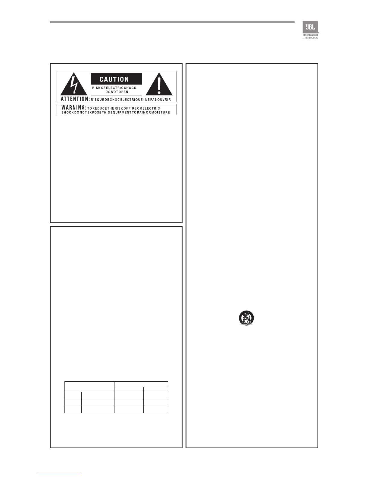
The symbols shown above are internationally accepted symbols
that warn of potential hazards with electrical products. The light-
ning flash with arrowpoint in an equilateral triangle means that
there are dangerous voltages present within the unit. The exclama-
tion point in an equilateral triangle indicates that it is necessary for
the user to refer to the owner’s manual.
These symbols warn that there are no user serviceable parts inside
the unit. Do not open the unit. Do not attempt to service the unit
yourself. Refer all servicing to qualified personnel. Opening the
chassis for any reason will void the manufacturer’s warranty.
Do not get the unit wet. If liquid is spilled on the unit, shut it off
immediately and take it to a dealer for service. Disconnect the unit
during storms to prevent damage.

4
IMPORTANT SAFETY INFORMATION
ELECTROMAGNETIC
COMPATIBILITY
This device complies with part 15 of the FCC Rules and the
Product specifications noted on the Declaration of Conformity.
Operation is subject to the following two conditions:
•this device may not cause harmful
interference, and
•this device must accept any interference received, including
interference that may cause undesired operation.
Operation of this unit within significant
electromagnetic fields should be avoided.
•use only shielded interconnecting cables.
U.K. MAINS PLUG WARNING
A molded mains plug that has been cut off from the cord is
unsafe. Discard the mains plug at a suitable disposal facility.
NEVER UNDER ANY CIRCUMSTANCES SHOULD YOU INSERT
A DAMAGED OR CUT MAINS PLUG INTO A 13 AMP POWER
SOCKET. Do not use the mains plug without the fuse cover in
place. Replacement fuse covers can be obtained from your local
retailer. Replacement fuses are 13 amps and MUST be ASTA
approved to BS1362.
If you want to dispose this product, do not mix it with gen-
eral household waste. There is a separate collection system
for used electronic products in accordance with legislation
that requires proper treatment, recovery and recycling.
Private household in the 25 member states of the EU, in Switzerland
and Norway may return their used electronic products free of charge to
designated collection facilities or to a retailer (if you purchase a similar
new one).
For Countries not mentioned above, please contact your local authorities
for a correct method of disposal.
By doing so you will ensure that your disposed product undergoes the
necessary treatment, recovery and recycling and thus prevent potential
negative effects on the environment and human health.
MAGNETIC FIELD
CAUTION! Do not locate sensitive high-gain equipment such as preamplifiers
or tape decks directly above or below the unit. Because this amplifier has a
high power density, it has a strong magnetic field which can induce hum into
unshielded devices that are located nearby. The field is strongest just above
and below the unit.
If an equipment rack is used, we recommend locating the amplifier(s) in
the bottom of the rack and the preamplifier or other sensitive equipment
at the top.

5
EC - DECLARATION OF CONFORMITY
Brand: JBL
Equipment Type: Commercial Audio Mixer-Amplifiers
Model names: CSMA 180, CSMA 1120, CSMA 240, CSMA 280, CSMA 2120
We, Harman International, declare under our sole responsibility that the product, to which this declaration relates, is in
conformity with the following standards.
Due to line current harmonics, we recommend that you contact your supply authority before connection.
We certify that the product identified above conforms to the requirements of the EMC Council Directive 89/336/EEC as amended
by 92/31/EEC, and the Low Voltage Directive 73/23/EES as amended by 93/68/EEC.
Report No. Description
EN 55103-1:2009 EMC Compatibility – Product Family Standard for Audio, Video, Audio-Visual and
Entertainment Lighting Control Apparatus for Professional Use, Part 1: Emissions
EN 55103-1:2009 Magnetic Field Emissions – Annex A @ 10cm and 20cm
EN 61000-3-2:2005,
AMD1:2008, & A2:2009
Limits for Harmonic Current Emissions (equipment input current less than or equal to 16A
EN 61000-3-3:2008 Limitation of Voltage Fluctuations and Flicker in Low-Voltage Supply systems Rated Current
less than or equal to 16A
EN 55022:2010 Limits and Methods of Measurement of Radio Disturbance Characteristics of ITE: Radiated
& Conducted, Class B Limits
EN 55103-2:2009 EMC Compatibility – Product Family Standard for Audio, Video, Audio-Visual and
Entertainment Lighting Control Apparatus for Professional Use, Part 2: Immunity
EN 61000-4-2:2009 Electrostatic Discharge Immunity (Environment E2-Criteria B, 4k V Contact, 8k V Air
Discharge)
EN 61000-4-3:2010
Ed 3.2
Radiated, Radio-Frequency, EMC Immunity (Environment E2, Criteria A)
EN 61000-4-4:2007 Electrical Fast Transient/Burst Immunity (Criteria B)
EN 61000-4-5:2006 Surge Immunity (Criteria B)
EN 61000-4-6:2006 Immunity to Conducted Disturbances Induced by Radio-Frequency Fields (Criteria A)
EN 61000-4-11:2004 Voltage Dips, Short Interruptions and Voltage Variation
Safety Standard:
IEC 60065:2001 – 7th
Ed., AMD1:2005,
& AMD2:2010
Safety Requirements – Audio, Video, and Similar Electronic Apparatus
European Representative’s
Name and Address:
David Budge
10 Harvest Close
Yateley, GU46 6YS
United Kingdom
Responsible for the technical
documentation is:
Wilson Zhou

6

7
1.0 Welcome
The JBL®CSMA series of Mixer-Amplifiers are a professional tool designed and built
for Installed sound applications. There are both single channel and two channel
models with four or eight mixer channels, respectively. They provide mixer capability
with independent level control for each input channel and amplification with a choice
of low impedance, 70V or 100V outputs.
The product includes a rack mounting kit for installations to a cabinet. The system
can be easily expanded with additional JBL Commercial Series Amplifiers and Com-
mercial Series Mixers. Provisions are included for a remote volume control using the
JBL CSR-V control module.
1.1 Features
• 4 or 8 inputs with 1 or 2 outputs, respectively
• Ideal for commercial and industrial use
• System may be expanded by adding JBL Commercial Series Mixers or
Commercial Series Amplifiers.
• Euro-block type mic/line input connectors and output connectors
• Independent Bass and Treble controls for each output channel
• VOX ducking during announcements
• Remote volume control capability using JBL CSR-V module and
standard ethernet cable
• Priority muting using PTT switch closure
• Configurable output routing
• Utilizes Crown’s DriveCoreTM technology providing excellent audio performance
with high efficiency
• 3 Year Warranty
*Warranty is only valid within the United States of America. For information on Warranty
outside of the U.S.A, please contact your local distributor.

8
1.2 Front Panel Controls and Indicators
A. Input Level Controls
B. Input signal presence is indicated by green illumination of the ring around
the input level controls
C. Output Volume Controls
D. Illuminated ring around the output volume control will light green with signal
presence while red indicates clipping, i.e. the signal has reached the
threshold of audible distortion.
E. Power Switch
F. Illuminated ring around the power switch. Green indicates that the unit is
connected to the AC mains and is in standby or sleep mode. Blue
indicates that the unit is on and in normal operating mode.
G. Tone Controls - Bass and Treble potentiometers on each output channel
Figure 1.2 Front View
A B C E
F
DG

9
1.3 Rear Panel Controls and Connectors - Four Channel
A. AC Power Inlet – Detachable IEC
B. Amplifier Output Connector
C. Auxiliary Line Level Output Connector
D. Hi-Z Switch – Enables the 70V and 100V outputs and activates the 70Hz high
pass filter
E. Phantom Power Switch – Applies 27V phantom power source for microphones.
F. Remote volume connector – RJ-45 style connector to connect to JBL CSR-V
control module
G. Mic/Line Selection Switch – Allows the user to select the gain depending upon
the source used
H. Mic/Line Input Connector – 3 pin Euro-block connector, balanced input (Ch2-4)
I. Dual RCA Input Connector – Stereo, unbalanced sources will be summed
together (Ch2-4)
J. Priority Input Connector – 5 pin Euro-block includes 3 pins for a balanced
input as well as two pins that, when shorted together, activates the priority
function. (Ch1)
K. VOX Adjustment – allows the input level to be set that will invoke priority
override. (CH1)
Figure 1.3 Rear View - CSMA 1120
AUX OUT
CSR-V ONLY
Hi-Z PHANTOM
CH3 INPUT
CH4 INPUT
CH2 INPUT
CH1 INPUT
100V 70.7V COM
MICLINE
MICLINE
MICLINE
MICLINE
MONO SUM MONO SUM
VOX
MONO SUM
100-240 V~ 50/60Hz 40W
CSMA 1120
MADE IN MALAYSIA
CAUTION - TO REDUCE THE RISK
OF ELECTRIC SHOCK, GROUNDING
OF THE CENTER PIN OF THE PLUG
MUST BE MAINTAINED.
5028384
AMP OUT
CLASS 2
WIRING
CH2-4 IN / AUX OUT
PRIORITY
A B D E G J KI
C F H

10
1.4 Rear Panel Controls and Connectors - Eight Channel
Figure 1.4 Rear View - CSMA 2120
5025056
100-240 V~ 50/60Hz 60W
CSMA 2120
CSR-V
21 3 4 5 6
7
8 9 10 11 12
MIC
MONO SUM MONO SUM MONO SUM
AMP 1AMP 2
AMP 1
AUX 1 OUT
CH4 INPUT
INPUT ROUTING
AUX 2 OUT
AMP 2
LINE
100V 70.7V COM
CH8 INPUT
CH3 INPUTCH7 INPUT
CH2 INPUTCH6 INPUT
CH1 INPUTCH5 INPUT
PRIORITY
PRIORITY
MADE IN MALAYSIA
MICLINE
MICLINE
MICLINE
MICLINE
MICLINE
MICLINE
MICLINE
CAUTION - TO REDUCE THE RISK OF
ELECTRIC SHOCK, GROUNDING OF THE
CENTER PIN OF THE PLUG MUST BE
MAINTAINED.
1 - CH1 TO AMP2
2 - CH2 TO AMP2
3 - CH3 TO AMP2
4 - CH4 TO AMP2
5 - AMP1 Hi-Z
6 - PHANTOM
7 - CH5 TO AMP1
8 - CH6 TO AMP1
9 - CH7 TO AMP1
10 - CH8 TO AMP1
11 - AMP2 Hi-Z
12 - NC
CH 1 VOX
CH 5 VOX
MONO SUM MONO SUM MONO SUM
OUTPUTS
CLASS 2
WIRING
I HG
A B D
C E
F J
A. AC Power Inlet – Detachable IEC
B. Amplifier Output Connector – Outputs available for low impedance or
constant voltage systems.
C. Remote Volume Control – RJ45 style connector to connect to a JBL CSR-V
control module.
D. Dip switches for input routing, phantom power, and 70/100V operation
E. Aux Out – Auxiliary line level output connector for each output channel.

11
5025056
100-240 V~ 50/60Hz 60W
CSMA 2120
CSR-V
21 3 4 5 6
7
8 9 10 11 12
MIC
MONO SUM MONO SUM MONO SUM
AMP 1AMP 2
AMP 1
AUX 1 OUT
CH4 INPUT
INPUT ROUTING
AUX 2 OUT
AMP 2
LINE
100V 70.7V COM
CH8 INPUT
CH3 INPUTCH7 INPUT
CH2 INPUTCH6 INPUT
CH1 INPUTCH5 INPUT
PRIORITY
PRIORITY
MADE IN MALAYSIA
MICLINE
MICLINE
MICLINE
MICLINE
MICLINE
MICLINE
MICLINE
CAUTION - TO REDUCE THE RISK OF
ELECTRIC SHOCK, GROUNDING OF THE
CENTER PIN OF THE PLUG MUST BE
MAINTAINED.
1 - CH1 TO AMP2
2 - CH2 TO AMP2
3 - CH3 TO AMP2
4 - CH4 TO AMP2
5 - AMP1 Hi-Z
6 - PHANTOM
7 - CH5 TO AMP1
8 - CH6 TO AMP1
9 - CH7 TO AMP1
10 - CH8 TO AMP1
11 - AMP2 Hi-Z
12 - NC
CH 1 VOX
CH 5 VOX
MONO SUM MONO SUM MONO SUM
OUTPUTS
CLASS 2
WIRING
I HG
A B D
C E
F J
F. Mic/Line Input Connector – 3 pin Euro-block connector for a balanced input
source. (Ch 2-4 & 6-8)
G. Dual RCA Input Connector – Stereo, unbalanced sources will be summed
together. (Ch 2-8)
H. Priority Input Connector – 5 pin Euro-block includes 3 pins for a balanced
input as well as two pins that, when shorted together, activates the priority
function. (Ch 1 & 5)
I. Mic/Line Selection Switch – Allows the user to select the gain depending upon
the source used.
J. VOX Adjustment – Allows the input level to be set that will invoke priority
override. (Ch 1 & 5)

12
2.0 Setup
2.1 Unpacking Your Amplifier
Please unpack and inspect your amplifier for any damage that may have occurred
during transit. If damage is found, notify the transportation company immediately.
Only you can initiate a claim for shipping damage. We will be happy to help
as needed. Save the shipping carton as evidence of damage for the shipper’s
inspection.
We also recommend that you save all packing materials so you will have them if you
ever need to transport the unit. Never ship the unit without the factory pack.
WARNING: Before you start to set up your amplifier, make sure you read and
observe the Important Safety Instructions found at the beginning of this manual.
2.2 Installing Your Amplifier
CAUTION: Before you begin, make sure your amplifier is disconnected from the
power source and all level controls turned completely down (counterclockwise).
Note: We recommend that any sensitive equipment be located at least 8 inches
(20cm) away from the amplifier.
To install the amplifier, you can use one of the following approaches:
• Rack mount the amplifier with the rack mounting kit, see Figure 2.2.2.
• Place a single amplifier on a surface with 12 inches of air space around the
unit for convection cooling. Rubber feet are included and can be attached
onto the underside of the chassis. For amplifier dimensions,
see Figure 2.2.1.

13
Figure 2.2.1 Dimensions
CSMA 180, CSMA 1120
CSMA 240, CSMA 280, CSMA 2120
Figure 2.2.2 Mounting Kit
long angle bracket
(CSMA180/CSMA1120 only)
flat bracket
(CSMA180/CSMA1120 only)
front angle bracket
rear angle brackets
rear flat brackets
218.44 mm [8.6 in] 303.4 mm [11.9 in]
43.3 mm
[1.7 in]
436.88 mm [17.2 in] 303.4 mm [11.9 in]
43.3 mm
[1.7 in]

14
Solution A: Rack Mounting Two Half Rack Mixer Amplifiers
To install two half-rack width units in your cabinet system, refer to Figure 2.2.3 and
follow the steps below:
1. Align two modules side by side and upside down with the front panel towards
the same direction.
2. Connect them with the flat bracket using the screws provided.
3. Attach the front angle brackets to each side of the front of the amplifier assem-
bly using the screws provided.
4. Attach the rear flat brackets to each side of the rear of the amplifier assembly
with the screws provided.
5. Install the assembly into the cabinet using the rack mount screws through the
front angle brackets. For details of installation in the chassis of the cabinet, refer
to the user guide of your cabinet.
6. Align the rear angle brackets with the proper holes at the rear of the cabinet and
attach using rack mount screws.
7. With the rear angle brackets to the outside of the flat brackets, attach them each
using a screw passing through two washers, the rear flat bracket and the rear
angle bracket as shown in the figure.
Figure 2.2.3 Rack mounting of two half rack Mixer units.

15
Figure 2.2.4 Rack Mounting a Half Rack Mixer Amplifier
Solution B: Rack Mounting Single Half Rack Mixer Amplifier
To install a single half-rack unit, refer to Figure 2.2.4 and follow the steps below:
1. Determine which side of the rack opening will be used for the amplifier and
attach the long angle bracket to the other side at the front of the amplifier using
the screws provided.
2. Attach the front angle brackets to each side of the front of the assembly, as
shown in the diagram, with the screws provided.
3. Install the assembly into the cabinet using the rack mount screws through the
front angle brackets. For details of installation in the chassis of the cabinet, refer
to the user guide of your cabinet.

16
Solution C: Rack Mounting Full Rack Mixer Amplifier
To install a full-rack width unit, refer to Figure 2.2.5 and follow the steps below:
1. Attach the front angle brackets to each side of the front of the amplifier using the
screws provided.
2. Attach the rear flat brackets to each side of the rear of the amplifier with the
screws provided.
3. Install the unit into the cabinet using the rack mount screws through the front
angle brackets. For details of installation in the chassis of the cabinet, refer to
the user guide of your cabinet.
4. Align the rear angle brackets with the proper holes at the rear of the cabinet and
attach using rack mount screws.
5. With the rear angle brackets to the outside of the flat brackets, attach them each
using a screw passing through two washers, the rear flat bracket and the rear
angle bracket as shown in the figure.
Figure 2.2.5 Rack Mounting Full Rack Mixer Amplifier

17
2.3 Ensuring Proper Cooling
When using an equipment rack, keep a minimum space of 4 inches (10cm) from the
top surface of the unit. Close any open spaces in the rack with blank panels. DO
NOT block any air vents. The side walls of the rack should be a minimum of 2 inches
(5 cm) from the amplifier sides. The back of the rack should be open.
2.4 Choosing Input Wire and Connectors
We recommend using pre-built or professionally wired balanced line (two-conductor
plus shield) 22-24 gauge cables to connect the amplifier balanced input by using the
included Euroblock connectors, see Figure 2.4. Unbalanced lines may be used, but
may result in hum or RF noise very long cable runs.
You can also use RCA connectors to connect audio devices, for example, CD/DVD
player. However, do not use both Euroblock and RCA audio input connectors on a
single channel at the same time.
NOTE: Custom wiring should only be performed by qualified personnel.
MONO SUM
AUDIO
SOURCE
AUDIO
SOURCE
AUDIO
SOURCE
AUDIO
SOURCE
Figure 2.4.1 Input Wiring
Note: Two RCA connectors are provided for summing left and right channels from a
stereo source. Do not use both Euroblock and RCA connectors concurrently for any
single input channel.

18
2.5 Output Wiring and Connectors
To drive distributed speaker systems designed to operate at 70V or 100V, connect to
the corresponding output terminals.
JBL recommends using pre-built or professionally wired, high-quality, two-conductor,
heavy gauge speaker wire. Speakers wires should be twisted cable, if possible. To
prevent the possibility of short-circuits, the wires should be stripped back no greater
than 6 mm (1/4 inch), see Figure 2.5.2.
Suggested below are guidelines to select the appropriate size of wire based on the
distance from amplifier to speaker. Check with local code as this may vary.
Distance Wire Size
Up to 25 ft. (7.6m) 16AWG
26-40 ft. (7.9-12.2m) 14AWG
8 Ohm Speaker
100V Speaker System
70V Speaker System
Figure 2.5 Output Wiring

19
2.6 Wiring Your Audio System
Typical input and output wirings are shown in Figure 2.6.
INPUTS: Connect input wiring for both channels using either the RCA or the
Euroblock input for each channel.
OUTPUTS: You may use either low impedance or high impedance speakers.
Always be sure to maintain the proper polarity when wiring speakers.
Low Impedance Speakers should be driven using the +/- pins of the amplifier output
connector. The minimum impedance an amplifier channel can drive is 4 Ohms.
Therefore, you can connect up to four 16 Ohm speakers, two 8 Ohm speakers or one
4 Ohm speaker to an amplifier output channel.
High Impedance Speakers should be driven using the appropriate (70V or 100V) pin
to speaker (+) and the COM pin to speaker (-) of the amplifier output connector. The
minimum impedance that can be driven from each output is provided in Appendix
A. Note that the HI-Z switch must be ON in order to provide audio to the high
impedance outputs.
WARNING: Do not connect to both low impedance speakers and high impedance
speakers from the same audio output channel.
Figure 2.6 Wiring Audio System
Professional audio system
AUX OUT
CSR-V ONLY
Hi-Z PHANTOM
CH3 INPUT
CH4 INPUT
CH2 INPUT
CH1 INPUT
100V 70.7V COM
MICLINE
MICLINE
MICLINE
MICLINE
MONO SUM MONO SUM
VOX
MONO SUM
100-240 V~ 50/60Hz 40W
CSMA 1120
MADE IN MALAYSIA
CAUTION - TO REDUCE THE RISK
OF ELECTRIC SHOCK, GROUNDING
OF THE CENTER PIN OF THE PLUG
MUST BE MAINTAINED.
5028384
AMP OUT
CLASS 2
WIRING
CH2-4 IN / AUX OUT
PRIORITY
CD /OPTICAL
SPK 1 + 2 VIRTUAL
LEVEL
CSR-V

20
2.7 Connecting to AC Mains
Connect your amplifier to the AC mains power source (power outlet) with the
supplied AC power cord. First, connect the IEC end of the cord set to the IEC
connector on the amplifier; then, plug the other end of the cord set to the AC mains.
When properly connected to a live power source, the power ring should illuminate
with a green color.
WARNING: The third prong of this connector (ground) is an important safety feature.
Do not attempt to disable this ground connection by using an adapter or other
methods.
Amplifiers don’t create energy. The AC mains voltage and current must be sufficient
to deliver the power you expect. You must operate your amplifier from an AC mains
power source with not more than a 10% variation above or below the specified line
voltage and within the specified frequency range indicated on the back panel of the
amplifier. If you are unsure of the output voltage of your AC mains, please consult
your electrician.
2.8 Protecting Your Speakers
It’s wise to avoid clipping the amplifier signal. Not only does clipping sound bad, but
it can damage high-frequency drivers. The built-in clip limiter prevents clipping.
Also, avoid sending strong subsonic signals to the amplifier. High-level, low-
frequency signals from breath pops or dropped microphones can blow out drivers.
You can switch to the HI-Z mode which, in addition to switching in the output
transformers for 70V and 100V speakers, activates the high-pass filter. The filter
prevents potentially damaging subsonic signals from going to the amplifier by
eliminating signals below 70Hz.
2.9 Startup Procedure
Use the following procedure when first turning on your amplifier:
1. Turn down the level of your audio source.
2. Turn down the level controls of the amplifier.
3. Power up the amplifier. The Power ring should change from green to blue.
4. Turn up the level of your audio source to an optimum level.
5. Turn up the Level controls on the amplifier until the desired loudness or power
level is achieved.
If you ever need to make any wiring or installation changes, don’t forget to
disconnect the power cord.
This manual suits for next models
4
Table of contents
Other JBL Music Mixer manuals