Manual 751 OB
latching mechanism is designed to make it easier to connect the two halves of the connector than to disconnect
them. The wires are held in adevice called acage-clamp which does not require that the wires be tinned,
although you may do that if you feel the need, ll^e cage-clamp will accommodate awire range of #14-#22
AWG. Strip tihe wires 1/4 inch, insert into the holes as indicated by the rear panel silkscreen, and tighten the
screws.
The Model 7510B Automatic Mixer provides +48 volt DC Phantom Power for condenser microphones.
Phantom Power gets its name from the fact tiiat the DC voltage is invisible to any BALANCED microphone
not specifically designed to use it. This includes most dynamic and ribbon microphones.. The Phantom
Power may be turned ON by the Phantom Power Switch on the Output Assembly. Turning this switch ON
supplies Phantom Power to all inputs except the auxiliary input located on the Output Assembly. Because of
the nature of the phantom circuitry it is not possible to use unbalanced connections with the Phantom Power
ON. DO NOT ATTEMPT TO USE AN UNBALANCED SOURCE WHENTHE PHANTOM POWER
SWITCH IS ON. SEVERE DAMAGE MAY OCCUR TO THE MICROPHONE (OR OTHER SOURCE
)
OR TO THE MIXER WHICH WILL NOT BE COVERED BY ANY MANUFACTURER'S WARRANTY.
Most microphones designed for Phantom Powering will operate from +48 volts, but if you have any doubts
about the use of aspecific microphone with the 7510B Mixer, consult the operating instructions for the
microphone or, if necessary, its manufacturer.
If none of your inputs require Phantom Power make sure that the Phantom Power Switch on the Output
Assembly is turned OFF.
If you wish to connect aLine level source to one of the inputs, but also need to supply Phantom Power to
condenser microphones, make sure that the source will not be damaged by application of +48 volt DC. If the
source is transformer balanced, that is fine. Otherwise you may need to install aDC blocking capacitor in
series with the input line. The capacitor should have its positive lead connected to the input terminal of the
751OB and its negative lead connected to the source. Acapacitor of 10p.F/50V minimum rating should be used
to avoid low frequency rolloff.
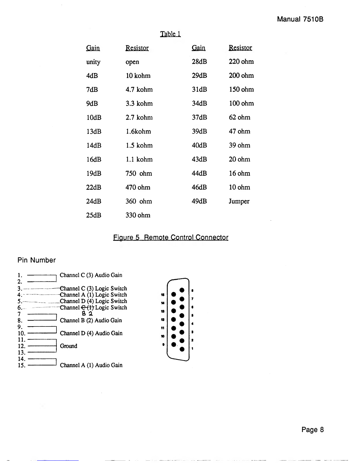
Pre-arop_Gain_Adiusl
The Input Preamp gain may be externally adjusted for optimum signal-to-noise and headroom. As shipped
from the factory the 15 pin connector on the rear panel of the Input Assembly includes four wire jumpers, one
for each of the four input channels. These jumpers, which set the gain of the input preamp at 49 dB, may be
removed and aresistor may be inserted in their place according to the values in Table 1on the next page. Use
only agood quality 1/8 or 1/4 watt carbon film or metal film resistor for best noise performance. Pin numbers
for the connectors are shown in Figure 5.
Wiring of Logic Circuits from Remote Control Connector
Figure 5shows the pin configuration for the Remote Control Connector on the rear panel of the Input
Assembly. In addition to the Preamp Gain adjustments described in the previous section, the 7510B also
provides acontact closure to ground when an input is activated. This contact closure, made through aCMOS
gate can switch ±5 volts with amaximum current of 10 milliamperes. Note that this is not avoltage source,
just acontact closure for an external source.
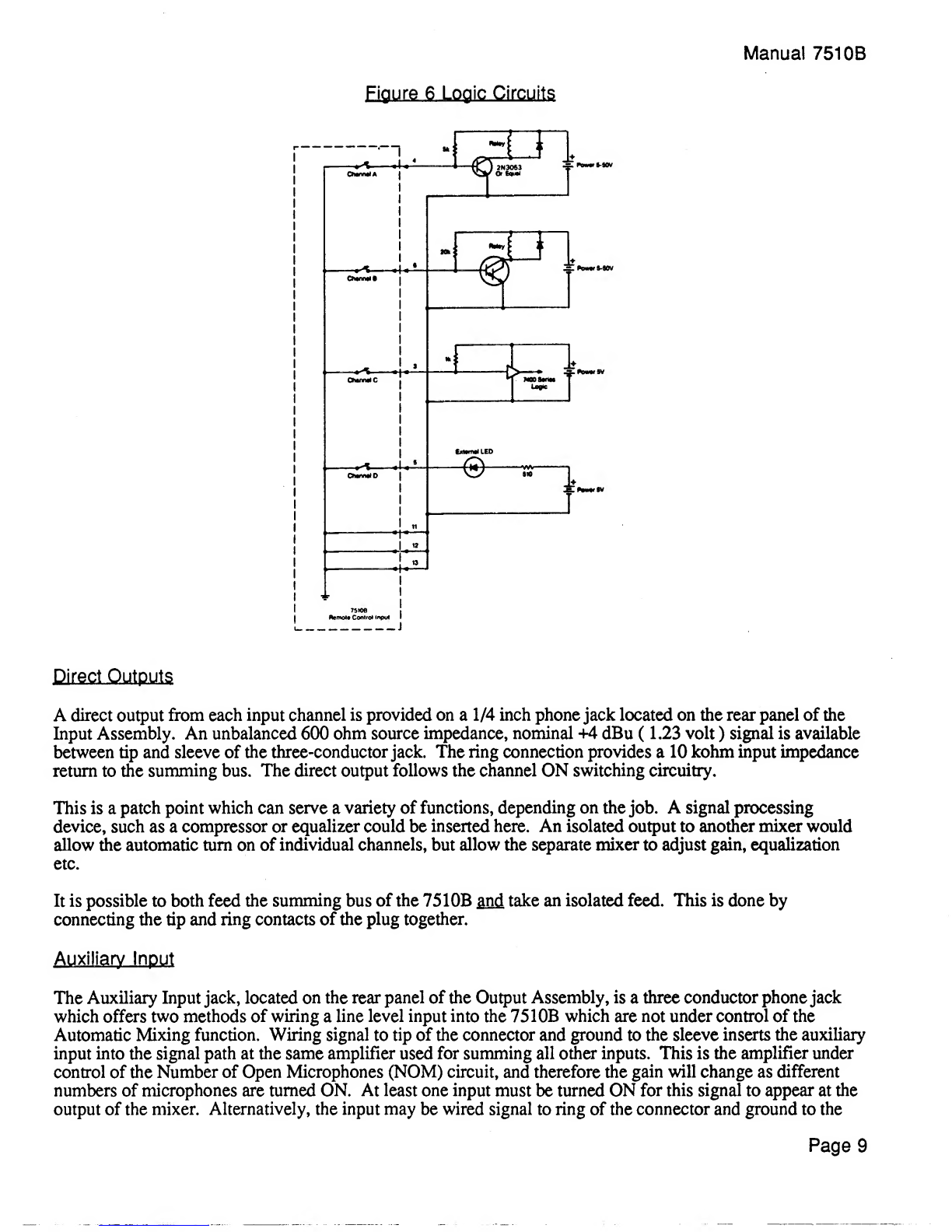
Figure 6shows several examples of circuits which could be used with this contact closure to activate relays,
drive Series 7400 TTL logic, LEDs, switch loudspeakers OFF to provide additional Acoustic Gain, switch
television cameras in ateleconferencing system etc.
Page 7