manuals.online logo
Brands
  1. Home
  2. •
  3. Brands
  4. •
  5. JBL
  6. •
  7. Subwoofer
  8. •
  9. JBL SP-150 User manual

JBL SP-150 User manual

Service Manual
SP150 / 230
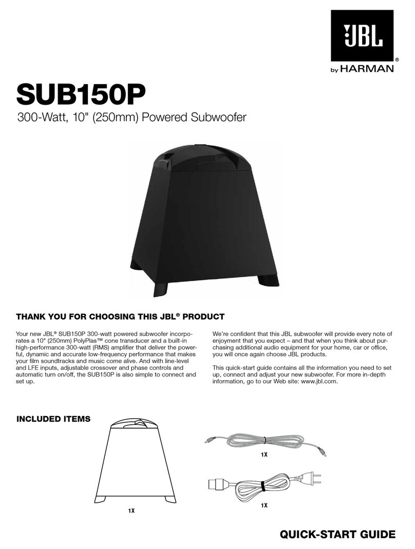
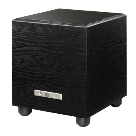
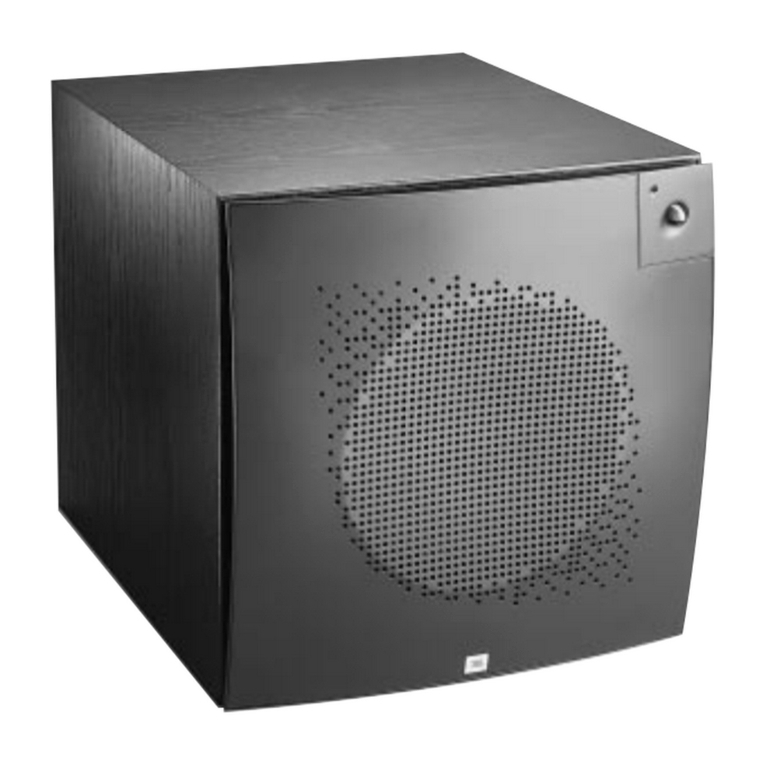
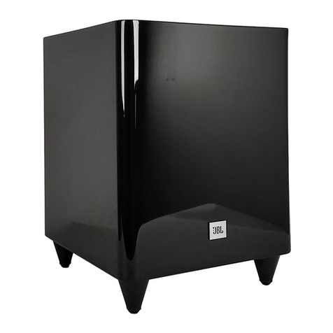
Active 10” Subwoofer.
Loft Series.
Released EU2012 Harman Consumer Group, Inc. Rev 0, 02/2012
8500 Balboa Boulevard
Northridge, California 91329
OWNER’S MANUAL 2
SPECIFICATIONS 7
PACKAGE GUIDE AND PARTS 8
EXPLODED VIEW 9
TROUBLESHOOTING FLOW CHART 11
PARTS LIST 12
SEMICONDUCTOR PINOUTS 18
PCB DRAWINGS 41
BLOCK DIAGRAMS 47
SCHEMATIC DIAGRAMS 49
CONTENTS
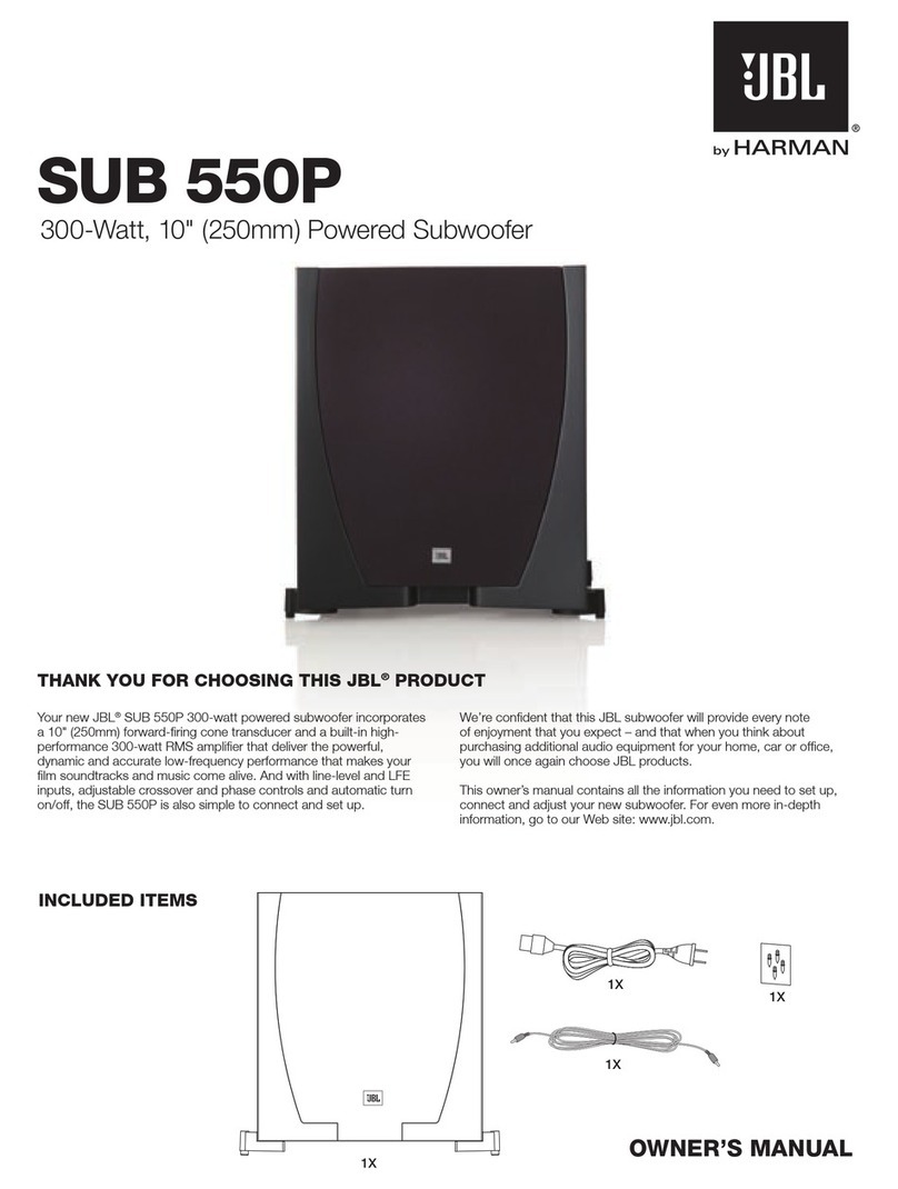
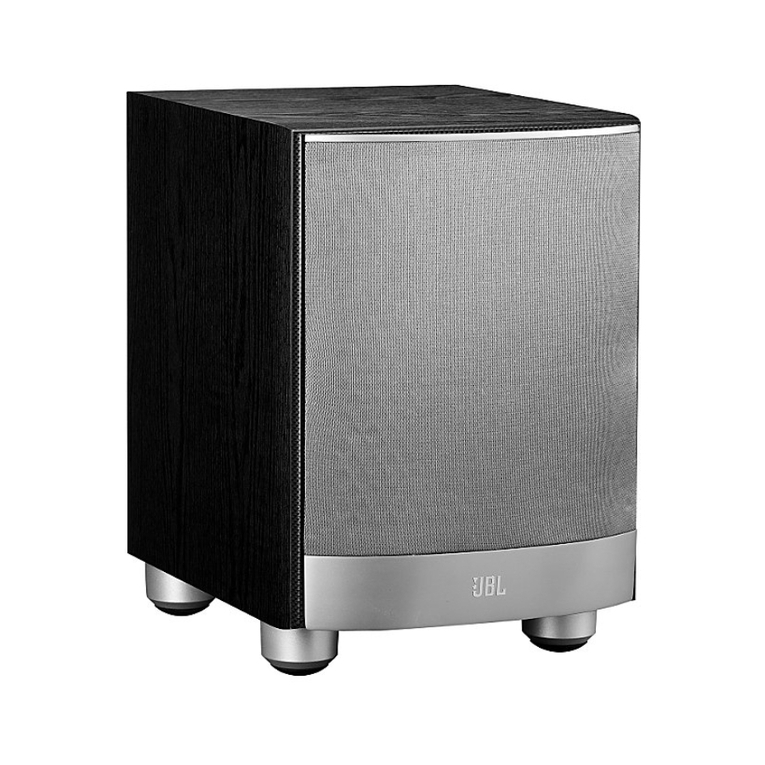
Your new JBL®SP-150 150-watt powered subwoofer incorporates
a 10" (250mm) down-firing cone transducer and a built-in high-
performance 150-watt amplifier that deliver the powerful, dynamic
and accurate low-frequency performance that makes your film
soundtracks and music come alive. And with line-level and
speaker-level inputs, adjustable crossover and phase controls and
automatic turn on/off, the SP-150 is also simple to connect and
set up.
We’re confident that this JBL subwoofer will provide every note
of enjoyment that you expect – and that when you think about
purchasing additional audio equipment for your home, car or
office, you will once again choose JBL products.
This quick-start guide contains all the information you need to set
up, connect and adjust your new subwoofer. For more in-depth
information, go to our Web site: www.jbl.com.
Thank You For Choosing This JBL®ProduCT
sP-150
150-Watt, 10" (250mm) Powered Subwoofer
owner’s ManuaL
JBL
150P / 230V Service Manual
Page 1 of 50
2
iMPorTanT saFeTY insTruCTions
1. Read these instructions.
2. Keep these instructions.
3. Heed all warnings.
4. Follow all instructions.
5. Do not use this apparatus near water.
6. Clean only with dry cloth.
7. Do not block any ventilation openings. Install in accordance with the
manufacturer’s instructions.
8. Do not install near any heat sources such as radiators, heat registers,
stoves, or other apparatus (including amplifiers) that produce heat.
9. Do not defeat the safety purpose of the polarized or grounding-type
plug. A polarized plug has two blades with one wider than the other.
A grounding-type plug has two blades and a third grounding prong.
The wide blade or third prong is provided for your safety. If the
provided plug does not fit into your outlet, consult an electrician for
replacement of the obsolete outlet.
10. Protect the power cord from being walked on or pinched, particularly
at the plugs, convenience receptacles and the point where they exit
from the apparatus.
11. Only use attachments/accessories specified by the manufacturer.
12. Use only with the cart, stand, tripod, bracket or table
specified by the manufacturer or sold with the apparatus.
When a cart is used, use caution when moving the cart/
apparatus combination to avoid injury from tip-over.
13. Unplug this apparatus during lightning storms or when
unused for long periods of time.
14. Refer all servicing to qualified service personnel. Servicing is required
when the apparatus has been damaged in any way, such as: when
the power supply cord or plug has become damaged, when liquid has
been spilled or objects have fallen into the apparatus, when the appa-
ratus has been exposed to rain or moisture, when the apparatus does
not operate normally, or the apparatus has been dropped.
15. Do not expose this apparatus to dripping or splashing and ensure
that no objects filled with liquids, such as vases, are placed on the
apparatus.
16. To completely disconnect this apparatus from the AC mains, discon-
nect the power supply cord plug from the AC receptacle.
17. The mains plug of the power supply cord shall remain readily operable.
18. Do not expose batteries to excessive heat such as sunshine, fire or
the like.
The lightning flash with arrowhead symbol, within an equilateral
triangle, is intended to alert the user to the presence of uninsulated
“dangerous voltage” within the product’s enclosure that may be of
sufficient magnitude to constitute a risk of electric shock to
persons.
The exclamation point within an equilateral triangle is intended to
alert the user to the presence of important operating and mainte-
nance (servicing) instructions in the literature accompanying the
product.
WARNING: To reduce the risk of fire or electric shock, do not expose this
apparatus to rain or moisture.
IMPORTANT: THE SUBWOOFER REQUIRES PROPER VENTILATION
AND IS NOT TO BE USED IN AN ENCLOSED ENVIRONMENT.
CorreCT disPosaL oF This ProduCT
This marking indicates that this product should not be
disposed with other household wastes throughout the EU. To
prevent possible harm to the environment or human health
from uncontrolled waste disposal, recycle it responsibly to
promote the sustainable reuse of material resources. To return
your used device, please use the return and collection systems
or contact the retailer where the product was purchased. They
can take this product for environmental safe recycling.
JBL
150P / 230V Service Manual

Page 2 of 50
3
www.jbl.com
English
suBwooFer rear-PaneL ConTroLs and ConneCTions
Auto-On switch:
• On/Auto: When this switch is set in the “On/Auto” position the
subwoofer will automatically turn itself on when it receives an audio
signal, and will enter the Standby mode when it has gone without
receiving an audio signal for 10 minutes.
• Off: Set the switch in the “Off” position to turn the subwoofer off.
Select this position if you will not be using the subwoofer for an
extended period of time, such as when on vacation.
Phase switch: This switch determines whether the subwoofer driver’s
piston-like action moves in and out in phase with the satellite speakers. If
the subwoofer were to play out of phase with the satellite speakers, the
sound waves from the satellites could partially cancel out the sound waves
from the subwoofer, reducing bass performance and sonic impact. This
phenomenon depends in part on the placement of all the speakers relative
to each other in the room.
Line-Level Input connector: If your receiver/processor has a dedicated
subwoofer output, use a single RCA audio cable (not supplied) to connect
it to the subwoofer’s Line-Level Input connector.
Crossover Frequency control: This control determines the highest
frequency at which the subwoofer reproduces sounds. The higher you set
the Crossover control, the higher in frequency the subwoofer will oper-
ate and the more its bass will “overlap” that of the satellite speakers. This
adjustment helps achieve a smooth transition of bass frequencies between
the subwoofer and the satellites for a variety of different rooms and sub-
woofer locations.
Volume control: Use this control to adjust the subwoofer’s volume. Turn
the knob clockwise to increase the volume; turn the knob counterclock-
wise to decrease the volume.
Speaker-Level Input connectors: If your receiver does not have a
dedicated subwoofer output, use speaker wire (not supplied) to connect
its Front Left and Front Right speaker outputs to the subwoofer’s Speaker-
Level Input connectors. Connect your system’s Front Left and Front Right
speakers to the subwoofer’s Speaker-Level Output connectors (see below).
Speakers and amplifiers have corresponding positive and negative (“+” and
“–”) connectors. The SP150 Speaker-Level Input connectors are marked
“+” and “–” beneath the connector levels. Additionally, the “+” connectors
have red markings, while the “–” connectors have black markings.
To ensure proper polarity, connect each “+” connector on the back of your
receiver or amplifier to the respective “+” (red) connector on each speaker.
Connect the “–” connectors in a similar way. Do not reverse polarities (i.e.,
“+” to “–” or “–” to “+”) when making connections. Doing so will cause
poor stereo imaging and diminished bass performance.
IMPORTANT: Make sure the “+” and “–” wires or connectors do not
touch each other or the other terminal. Touching wires can cause
a short circuit that can damage the subwoofer or your receiver/
amplifier.
Speaker-Level Output connectors: If you used the subwoofer’s Speak-
er-Level Input connectors to connect it to your receiver, you must connect
your system’s Front Left and Front Right speakers to the subwoofer’s
Speaker-Level output connectors. To ensure proper polarity, connect each
“+” connector on the subwoofer to the respective “+” (red) connector on
each speaker. Connect the “–” connectors in a similar way. Do not reverse
polarities (i.e., “+” to “–” or “–” to “+”) when making connections. Doing so
will cause poor stereo imaging and diminished bass performance.
IMPORTANT: Make sure the “+” and “–” wires or connectors do not
touch each other or the other terminal. Touching wires can cause
a short circuit that can damage the subwoofer or your receiver/
amplifier.
AC Fuse holder: The SP150 is factory-equipped with a 2A/250V AC fuse.
If the fuse ever blows:
1. Unplug the subwoofer’s power cord from the wall.
2. Use a screwdriver to remove the blown fuse.
3. Replace the fuse with an identical 2A/250V fuse.
CAUTION: FOR CONTINUED PROTECTION AGAINST FIRE,
REPLACE THE FUSE ONLY WITH THE SAME TYPE AND RATING.
Power cord: After you have made and verified all subwoofer and speaker
connections described in this manual, plug the power cord into an ac-
tive, unswitched electrical outlet for proper operation of the subwoofer.
DO NOT plug this cord into the accessory outlets found on some audio
components.
Crossover Frequency
Control
Auto-On Switch
Phase Switch
AC Fuse
Holder
Speaker-Level
Input Connectors
Line-Level
Input Connector
Speaker-Level
Output Connectors
Volume Control
Power Cord
JBL
150P / 230V Service Manual
Page 3 of 50
4
PLaCing The suBwooFer
ConneCTing The suBwooFer
The performance of a subwoofer is directly related to its placement in the listening room
and its physical position relative to the other speakers in the system.
While it is true that in general our ears do not hear directional sounds at the low
frequencies where subwoofers operate, when installing a subwoofer within the limited
confines of a room, the reflections, standing waves and absorptions generated within
the room will strongly influence the performance of any subwoofer system. As a result,
the specific location of the subwoofer in the room does become important to the
amount and quality of bass that is produced.
For example, placing the subwoofer next to a wall generally will increase the amount of
bass in the room; placing it in a corner (1) generally will maximize amount of bass in the
room. However, corner placement can also increase the destructive effect of standing
waves on bass performance. This effect can vary depending on the listening position
– some listening positions may yield very good results while others may have far too
much (or too little) bass at certain frequencies.
In many rooms, placing the subwoofer along the same plane as the left and right speak-
ers (2) can produce the best integration between the sound of the subwoofer and that
of the left and right speakers. In some rooms, the best performance could even result
from placing the subwoofer behind the listening position (3).
We strongly recommend that you experiment with placement before choosing a final
location for your subwoofer. One way you can determine the best location for the sub-
woofer is by temporarily placing it in the listening position and playing music with strong
bass content. Move around to various locations in the room while the system is playing
(putting your ears where the subwoofer would be placed), and listen until you find the
location where the bass performance is best. Place the subwoofer in that location.
Front Left
Speaker
TV
Center
Speaker Front Right
Speaker
Surround Left
Speaker Surround Right
Speaker
1.
2.
3.
TO A RECEIVER OR PREAMP/PROCESSOR WITH A LINE-LEVEL SUBWOOFER OUTPUT
SP150
Subwoofer
RCA Audio Cable
(not supplied)
Receiver or
Amplifier
JBL
150P / 230V Service Manual
Page 4 of 50
5
www.jbl.com
English
TO A RECEIVER WITHOUT A LINE-LEVEL SUBWOOFER OUTPUT
FRONT
SPEAKERS
SURROUND
SPEAKERS
CENTER
SPEAKER
SP150
Subwoofer
Front Left
Speaker
Speaker Wire
(not supplied)
Speaker Wire
(not supplied)
Receiver or Amplifier
Front Right
Speaker
JBL
150P / 230V Service Manual

Page 5 of 50
6
TURNING THE SUBWOOFER ON AND OFF
· If you want the subwoofer to automatically turn on when it receives
an audio signal and automatically turn off after not receiving an audio
signal for 10 minutes, set the Auto-On switch in the “Auto” position.
· If you want to turn the subwoofer off, set the Auto-On switch in the
“Off” position.
SUBWOOFER ADJUSTMENTS: CROSSOVER CONTROL
The Crossover control adjusts the subwoofer’s
built-in crossover between 50Hz and 150Hz. The
higher you set the Crossover control, the higher in
frequency the subwoofer will operate and the more
its bass will “overlap” that of the satellite speakers.
This adjustment helps achieve a smooth transition
of bass frequencies between the subwoofer and
the satellites for a variety of different rooms and
subwoofer locations.
To set the Crossover control, listen for the
smoothness of the bass. If the bass seems too strong at certain
frequencies, try a lower Crossover control setting. If the bass seems too
weak at certain frequencies, try a higher Crossover control setting.
SUBWOOFER ADJUSTMENTS: VOLUME
Use the Volume control to set the subwoofer’s
volume. Turn the knob clockwise to increase
the subwoofer’s volume; turn the knob
counterclockwise to decrease the volume. Once
you have balanced the subwoofer’s volume with
that of the other speakers in your system, you
shouldn’t have to change it.
Notes on Setting Subwoofer Volume:
• Sometimes the ideal subwoofer volume setting
for music is too loud for films, while the ideal
setting for films is too quiet for music. When setting the subwoofer
volume, listen to both music and films with strong bass content and
find a “middle ground” volume level that works for both.
• I f your subwoofer always seems too loud or too quiet, you may want
to place it in a different location. Placing the subwoofer in a corner will
tend to increase its bass output, while placing it away from any walls
or corners will tend to lessen its bass output.
SUBWOOFER ADJUSTMENTS: PHASE
The Phase switch determines whether the subwoofer driver’s
piston-like action moves in and out in phase with the satellite
speakers. If the subwoofer were to play out of phase with the
satellite speakers, the sound waves from the satellites could
partially cancel out the waves from the subwoofer, reducing
bass performance and sonic impact. This phenomenon
depends in part on the placement of all the speakers relative
to each other in the room.
Although in most cases you should leave the Phase switch in the “Normal”
position, there is no absolutely correct setting for the Phase switch. When
the subwoofer is properly in phase with the satellite speakers, the sound
will be clearer and have maximum impact, and percussive sounds like
drums, piano and plucked strings will sound more lifelike. The best way
to set the Phase switch is to listen to music that you know well and to set
the switch in the position that gives drums and other percussive sounds
maximum impact.
sPeCiFiCaTions
Low-frequency
transducer: 10" (250mm) cone (down-firing)
Enclosure type: Ported (front-firing)
Amplifier power: 175 watts
Frequency response: 28Hz – 170Hz
Audio controls: Volume level, crossover frequency,
phase
Connections: RCA line-level inputs; speaker-level
inputs and outputs
Power requirement: 100V – 240V AC, 50Hz/60Hz
Power consumption: <1.0W (standby); 175W (maximum)
Dimensions (W x H x D): 12-1/2" x 16" x 14"
(318mm x 406mm x 356mm)
Weight: 22.9 lb (10.4kg)
oPeraTing The suBwooFer
© 2012 HARMAN International Industries, Incorporated. All rights reserved.
JBL is a trademark of HARMAN International Industries, Incorporated, registered in the United States and/or other countries.
Features, specifications and appearance are subject to change without notice.
Part No. 950-0457-001, Rev.: A
HARMAN International Industries, Incorporated
8500 Balboa Boulevard, Northridge, CA 91329 USA www.jbl.com
JBL
150P / 230V Service Manual
Page 6 of 50
150 watts
35Hz - 180Hz
JBL
150P / 230V Service Manual
Page 7 of 50
This place with CUT is to fit
front of subwoofer
packing
illustration
sub
PE bag
EPE bag
styrofoam top cover
manual
styrofoam bottom cover
desiccant, 25g/bag
carton
sealing tape
29040004
JBL
150P / 230V Service Manual
Page 8 of 50
exploded view
No.
P/N.
Name
Q'ty
Q'ty
Name
P/N.
No.
port tube
paper tube
tube head
cabinet
self-tapping
screw
SP150/230
AMP
self-tapping
screw
lighted badge
woofer
foot
6-1
5-1
5-2
5-3
5-4 5-5
6-3
6-2
6-4 6-5
12
8
34
7
9
10
11
12
13-1
13-2
13-3
13-4
13-5
13-8
13-6
13-7
14
15
16
17
1 10100204 铝面板220*190*3.0mm 1
2 K0100356 前置板 1
3 K0100354 功放板 1
4 70010021 带平垫机牙螺丝M3*6 1
5 70010022 机牙螺丝M3*6 5
6 10210053 铜柱S5*10mm*M3 5
7 10250022 铁支架 1
8 30060099 泡棉(双面备胶) 1
9 19070001 保险丝座 1
10 20520003 线扣 1
11 20210005 旋扭 2
12 70020034 ¢3自攻螺丝 5
13 70010031 机牙螺丝M3*8 8
14 10080121 散热片30*15*13.2mm 1
15 70010051 机牙螺丝M3 * 1 8 1
16 70010043 带平垫机牙螺丝M3* 1 2 2
17 70070002 外六角螺母带平垫弹垫 1
1R 序号
料号 料号
名称 名称
用量 用量
JBL
150P / 230V Service Manual
Page 9 of 50
Part No. Part Name Q'ty No. Part No. Part Name Q'ty
AL panel
filter pcb
poweramp pcb
M.screw with flat washer M3*6
M.screw
spacer S5*10mm*M3
steel bracket
EVA piece
fuse holder
cord strain relief bushing
knob
self-tapping screw
M.screw
heatsink, 30*15*13.2mm
M.screw, M3*18
M.screw with flat washer M3*12
outer-hex nut,with flat/spring washer
no or lower
no or lower
no or lower
no or lower
SP150/230 Trouble Shooting Flow Chart
NO ±VCC(±2V)
±19V(±1V)
±12V(±1V)check R82.R83
check U4.Q1.U1.BD3.T1①Check DC
voltages
② NO
POWER
ON
OK
±10V(±1V)check Q8.Q21.Q22.Q23.R80.R81
check U4 , U5, and parts related to them
emphasis is to check capacitors related
with U4.U5
③
②
NO
Test Frequency
OK
OK
④
①check filter pcb:U5.U6.U7.VR1.VR2, and parts
related to them
emphasis is to check feedback resistor and
capacitor of OPAMP IC.
②check post-stage: pin8,9,16,21 of U2, and
parts related to them
emphasis is to check if U2 is defective,
emphasis is to check if isQ1.C3.D5.D6.D7
defective,
and check if R26.R25.C57.C54 is defective
NO
Test
Sensitivity
OK
check U6-A and parts related to it,
check -12V voltage(±1V)
NO
NO
check ±VCC voltage
⑤Test limiter
circuit
OK
check if U2 is defective
test method pls
refer to above
items
check limiter circuit
emphasis is to check if U2.C64.C65
is defective
NO
⑥test power and
distortion
OK
⑦① check U2 and C64.C65.L5.L7.C53.C265 related to it,
see if any part got defective.
② check all filter capacitors of DC voltage points
check C3(filter capacitor to GND)
NO
test idle noise
Test DC
voltages
Response
JBL
150P / 230V Service Manual
Page 10 of 50
JBL SP150/230 powered subwoofer spare parts list.
AMP part no. BB000014 Product:Sub Amplifier
1Unite
2SET
3PCS
4PCS
5PCS
6PCS
7PCS
8PCS
9PCS
10 PCS
11 PCS
12 PCS
13 PCS
14 PCS
15 PCS
16 PCS
17 PCS
18 PCS
19 PCS
20 PCS
21 PCS
22 PCS
23 PCS
24 PCS
25 PCS
26 PCS
27 PCS
28 PCS
29 PCS
30 PCS
31 PCS
32 PCS
33 PCS
34 PCS
35 PCS
36 PCS
37 PCS
38 PCS
39 PCS
40 PCS
41 PCS
18010042 Diode
U514040072 IC TL431A,TO-92,L=4mm (ST)
11080033 Jumper Wire Φ0.6*15mm L=4mm
P6KE200A vertical P=7.5mm L=4mm
3JP7-9
1D15
1
11080030 Jumper Wire
11080032 Jumper Wire 2JP5-6
8JP10-17
OB2269CP SOP8
Φ0.6*5mm L=4mm
Φ0.6*7.5mm L=4mm
Φ0.6*12.5mm L=4mm
11080029 Jumper Wire
1D4
1U4
1JP1
18070048 SMT Diode
18070059 SMT Diode
14040183 SMT IC
3D2.3.9
1/2W 6.8V LL-34
1/2W 20V LL-34
SE1K(HER107) SMA (US1M)
1N4007(M7) D-SMA(DO-214AC)
18070062 SMT Diode
1D1
1ZD1
1ZD4
50050089 SMT Cap.
18070001 SMT Diode
18070030 SMT Diode
1C63
153/50V ±10%0805 X7R
105/25V ±10%0805 X7R
473/50V ±10%0805 X7R
1/2W IN4148 LL-34
50050029 SMT Cap.
1C27
2C265.53
1C10
50050022 SMT Cap.
50050012 SMT Cap.
50050067 SMT Cap.
7C4-6.19-22
1W 22Ω ±5%2512
1W 100K ±5% 2512
104/50V ±10%0805 X7R
102/50V ±10%0805 X7R
11170615 SMT Res.
1R13
2R14.15
1R23
11170520 SMT Res.
11170599 SMT Res.
11170515 SMT Res.
2R32.33
1/4W 1M ±1%1206
1/4W 2M ±1%1206
0.75W 10Ω ±5%2010
1W 0.1Ω ±1% 2512
11170487 SMT Res.
1R2
3R17.19.20
2R1.16
11170485 SMT Res.
11170486 SMT Res.
11170260 SMT Res.
1R5
1/4W 22Ω ±1%1206
1/4W 510Ω ±1%1206
1/4W 24K ±1%1206
1/4W 750K ±1%1206
11170484 SMT Res.
1R4
1R18
1R22
11170481 SMT Res.
11170480 SMT Res.
11170483 SMT Res.
2R25.26
1/8W 10K ±1%0805
1/8W 18K ±1%0805
1/4W 4.7Ω ±1%1206
1/4W 5.1Ω ±1%1206
11170084 SMT Res.
1R37
1R31
1R10
1/8W 9.1K ±1% 0805
11170069 SMT Res.
11170073 SMT Res.
11170074 SMT Res.
11170065 SMT Res.
1
2R34.35
1R8
1/8W 3.6K ±1%0805
1/8W 5.6K ±1% 0805
1/8W 7.5K ±1%0805
1R11
11170343 SMT Res.
R7
11170036 SMT Res. 1/8W 1K ±1%0805
11170056 SMT Res.
1R24
1/8W 2.7K ±1% 0805
1
R9
Q'ty
11170017 SMT Res. 1/8W 220Ω ±1%0805 1
10010037 PCB MS100-
PWR&AMP,V.A2,150*85*1.6mm,green
oil, semi-glass fiber
DesignationPart No. Part Name
K0100354 POWERAMP pcb RX150N PCB ASSY. 1
Specs
JBL
150P / 230V Service Manual
Page 11 of 50
42 PCS
43 PCS
44 PCS
45 PCS
46 PCS
47 PCS
48 PCS
49 PCS
50 PCS
51 PCS
52 PCS
53 PCS
54 PCS
55 PCS
56 PCS
57 PCS
58 PCS
59 PCS
60 PCS
61 PCS
62 PCS
63 PCS
64 PCS
65 PCS
66 PCS
67 PCS
68 PCS
69 PCS
70 PCS
71 PCS
72 PCS
73 PCS
74 SET
75 PCS
76 PCS
77 PCS
78 PCS
11170061 SMT Res.
1/8W 6.8K ±1% 080511170068 SMT Res.
1/8W 4.99K ±1%0805
1R29
1R38
2R80.81
11170059 SMT Res.
TDA8920BTH-M V.A1&MS100-
P,V.A2,69.3*91.5+5+5*1.6mm green oil,
FR4 double side 1
1/8W 4.7K ±1% 0805
10020121 PCB
16080154 SPK wire SUB
K0100338 Power Moudule MS100 PCB ASSY.
1
30010021 heat-shrinkable tubing Φ1*15mm black
1R12
14010055 fast rectifier
UL1015,18#,2P,L=500mm,red/black
16130051 Cables
11200018 Thermister
FMG23S TO220 400V 10A
2cover R12
2D5-6
1A-B
M3*8mm black, with flat&spring washer
RS406L H=10mm L=4mm
UL1617 18# L=80+5+5mm red
100KΩ NTC ±5﹪L=19mm
18020019 bridge rectifier
1fix Q1
1fix Q1
1BD3
40370032 connector
10080055 heatsink for transistor
70010029 M.screw
1CON2
EC35 100W vertical
CS10N60 TO-220
2532-07-180 degree
23*15*10.5mm,single pin Ф1.7mm
14010167 MOS
1L1
1T1
1Q1
24060130 inductor
24060123 common-mode inductor
13030099 hi-FREQ transformer
2L3.6
Φ3.5*9mm vertical P=5mm L=4mm
16*19 22uH L=4mm
22uH/3A,Φ8*10mm P=5mm L=4mm
L-EE25-12mH diameter=0.6mm
24060129 inductor
2L2.4
2L8.9
2L5.7
17010240 E.C.
24060006 color-code inductor
24060052 bead
1C1
220uF/35V,105
℃
,+/-20%,Φ8*12mm
L=4mm
1000uF/35V,105
℃
,+/-20%,Φ13*21mm
L=4mm
120uF/400V,105
℃
,+/-20%,Φ18*36mm
L=4mm
1/2W 100uH vertical P=5mm L=4mm
17040023 E.C.
1C58
2C12.16
4C2.11.13.14
17010055 E.C.
17010060 E.C.
17010074 E.C.
6C17.18.59.60.15.29
0.47uF/50V,105
℃
,+/-20%,Φ5*11mm
L=4mm
22uF/50V,105
℃
,+/-20%,Φ5*11mm
L=4mm
100uF/35V,105
℃
,+/-20%,Φ6.3*11mm
L=4mm
100uF/63V,105
℃
,+/-20%,Φ10*17mm
L=4mm
17010032 E.C.
2CX1.3
2C8.23
1C3
50110005 Y1 Cap.
50080006 X2 Cap.
17010003 E.C.
1CY3
684/100V ±5%P=5mm L=4mm
471/400V ±20%P=10mm L=4mm
222/400V ±20%P=10mm L=4mm
224/275V ±20% 18*6*12mm P=15mm
L=4mm
50110006 Y1 Cap.
2C54.57
2C55-56
2CY1.2
224/100V ±5%P=5mm L=4mm
50010071 ceramic Cap.
50030030 MOF
50030031 MOF
R21
2C39.40
1C9
50010046 ceramic Cap.
472/1KV ±20% blue P=5mm L=4mm
11150017 wirewound Res.
60020002 photocoupler PC817 DIP4 1
2W 0.1Ω 5% Vertical, non-inductive
L=4mm
U1
471/250V ±5% SL P=5mm L=4mm
1
JBL
150P / 230V Service Manual

Page 12 of 50
79 PCS
80 PCS
81 PCS
82 PCS
83 PCS
84 PCS
85 PCS
86 PCS
87 PCS
88 PCS
89 PCS
90 PCS
91 PCS
92 PCS
93 PCS
94 PCS
95 PCS
96 PCS
97 PCS
98 PCS
99 PCS
100 PCS
101 PCS
102 PCS
103 PCS
104 PCS
105 PCS
106 PCS
107 SET
108 PCS
109 PCS
110 PCS
111 PCS
112 PCS
113 PCS
114 PCS
115 PCS
116 PCS
117 PCS
118 PCS
119 PCS
120 PCS
121 PCS
1/8W 3.6K ±1%0805
1/8W 5.1K ±1% 080511170062 SMT Res.
2R1.71
1R70
1R76
11170343 SMT Res.
11170052 SMT Res.
11170056 SMT Res.
1R18
1/8W 2.1K ±1%0805
1/8W 2.2K ±1%0805
1/8W 2.7K ±1% 0805
1/8W 3K ±1% 0805
11170046 SMT Res.
1R78
1R54
1R75
11170041 SMT Res.
11170044 SMT Res.
11170045 SMT Res.
1R29
1/8W 560Ω ±1%0805
1/8W 1K ±1%0805
1/8W 1.5K ±1%0805
1/8W 2K ±1%0805
11170036 SMT Res.
2R69.73
1R11
3R68.19.200
1/8W 220Ω ±1%0805
11170011 SMT Res.
11170017 SMT Res.
11170146 SMT Res.
4R16.23.62.R00
1R4
11170001 SMT Res.
1/8W 100Ω ±1% 0805
10010051 PCB
40360042 PIN header
CON3B
K0100356 filter PCB(preamp) SP150N JBL PCB ASSY.
RX-PRE V.A1 132*58*1.6mm green oil
94V0,single side
40360028 PIN header 9P P=2.54mm 90 degree L=12mm
40360041 PIN header 6P P=2.54mm 180 degree
9P P=2.54mm 180 degree
1CON2B
1CON1A
1
1/8W 0Ω ±1% 0805
1
17020015 E.C.
17010073 E.C. 1C71
6C36-38.41-43
2SA1015GR PNP TO-92 L=4mm
10uF/50V,105
℃
,+/-20%,Φ4*7mm
L=4mm
22uF/25V,105
℃
,+/-20%,Φ4*7mm
L=4mm
220uF/25V,105
℃
,+/-20%,Φ6.3*12mm
L=4mm
17020056 E.C.
1Q6
1Q21
1C70
14040205 SMT IC
14010001 Transistor
14010002 Transistor
1U2
MMBT3904LT1(1AM)SOT23 NPN
MOTOROLA
MMBT3906LT1(2A)SOT23 PNP
MOTOROLA
TDA8920CTH HSOP24(NXP)
2SC1815GR NPN TO-92 L=4mm
14010126 SMT Transistor
2Z1.3
1Q3
3Q2.22.23
18070004 SMT Diode
18070008 SMT Diode
14010125 SMT Transistor
2ZD2.3
224/100V ±10%1206 X7R
1/2W IN4148 LL-34
1/2W 5.6V LL-34
1/2W 10V LL-34
18070001 SMT Diode
1C67
5C61.62.66.69.26
2D7.8
50050040 SMT Cap.
50050063 SMT Cap.
50050129 SMT Cap.
8C25.30.32.35.48.50.51.31
104/50V ±10%0805 X7R
153/50V ±10%0805 X7R
224/50V ±10%0805 X7R
475/25V ±10%0805 X7R
50050067 SMT Cap.
6C33.34.68.72.24.49
4C44-47
2C64.65
11170613 SMT Res.
50050051 SMT Cap.
50050022 SMT Cap.
1R83
1/4W 4.7Ω ±1%1206
1/4W 825Ω ±1%1206
1/4W 1.54K ±1%1206
471/50V ±10%0805 X7R
11170612 SMT Res.
1R43
2R13.16
1R82
11170107 SMT Res.
11170345 SMT Res.
11170481 SMT Res.
2R27.28
1/8W 20K ±1%0805
1/8W 39K ±1%0805
1/8W 51K ±1%0805
1/8W 68K ±1%0805
11170086 SMT Res.
11170100 SMT Res.
2R36.261
2R84.85
1R30
1/8W 10K ±1%080511170074 SMT Res.
JBL
150P / 230V Service Manual
Page 13 of 50
122 PCS
123 PCS
124 PCS
125 PCS
126 PCS
127 PCS
128 PCS
129 PCS
130 PCS
131 PCS
132 PCS
133 PCS
134 PCS
135 PCS
136 PCS
137 PCS
138 PCS
139 PCS
140 PCS
141 PCS
142 PCS
143 PCS
144 PCS
145 PCS
146 PCS
147 PCS
148 PCS
149 PCS
150 PCS
151 PCS
152 1108002
9PCS
153 1108003
0PCS
154
1108003
1
PCS
155
1108003
4
PCS
156 PCS
157 PCS
158 PCS
159 PCS
160 PCS
161 PCS
1uF/50V,105℃,+/-20%,Φ5*11mm
L=4mm blue
4.7uF/50V,105℃,±20%,Φ5*11mm
L=4mm
17010004 E.C.
17010015 E.C.
1C25
1C8
1C4
50060011 MET Cap.
473/100V ±5% 7.2*6.5*2.5mm L=4mm
683/100V ±5% 7.2*6.5*2.5mm L=4mm
50060035 MET Cap.
50060043 MET Cap.
124/100V ±5% 7.2*6.5*2.5mm L=4mm
1Q1
4C24.26.31.32
1C27
14010074 MOS
1JMP2
Φ0.6*5mm L=4mm
Φ0.6*7.5mm L=4mm
Φ0.6*10mm L=4mm
Φ0.6*17.5mm L=4mm
2SJ108,L=4mm (Fairchild)
7JMP1.21.13.26.14.17.29
Jumper Wire
Jumper Wire
NJM4558 SOP8 JRC
NJM4560 SOP8 JRC
Jumper Wire
Jumper Wire
12 JMP25.4.6.8.22.9.15.10.11.2
4.19.20
9JMP5.7.16.18.23.27.28.12.C
30
5U2.4-714040097 SMT IC
1
7D2.3-4.6-9
U114040119 SMT IC
1/2W 3.3V LL-34
SMT Cap.
2Z1-218070037 SMT Diode
104/50V ±10%0805 X7R
1/2W IN4148 LL-34
50050022 SMT Cap.
102/50V ±10%0805 X7R
1C40
18070001 SMT Diode
2C33.CP
5C12-14.37.200
50050012
50050038 SMT Cap.
101/50V ±5%0805 NPO 2C6.23
221/50V ±5%0805 NPO
50050010 SMT Cap.
11170622 SMT Res. R03.04
11170406 SMT Res. 1W 680Ω ±5% 2512 2R01.02
2
11170376 SMT Res. 1/4W 3K ±1% 1206
1R72
11170628 SMT Res.
1W 200Ω ±5% 2512
11170138 SMT Res.
11170139 SMT Res.
1/4W 7.5K ±1%1206
1R30
1D5
1R25
1/8W 470K ±1%0805
1/8W 680K ±1%0805
1/8W 2M ±1%0805
1/8W 2.2M ±1%0805
11170134 SMT Res.
1R13
3R81.05.08
2R07.06
11170126 SMT Res.
11170127 SMT Res.
11170427 SMT Res.
1R20
1/8W 200K ±1%0805
1/8W 220K ±1%0805
1/8W 300K ±1%0805
1/8W 330K ±1%0805
11170124 SMT Res.
1R17
1R67
1R74
11170116 SMT Res.
11170119 SMT Res.
11170123 SMT Res.
4R21.64.09.010
1/8W 30K ±1%0805
1/8W 51K ±1%0805
1/8W 100K ±1% 0805
1/8W 120K ±1%0805
11170107 SMT Res.
1R14
4R57.59.61.63
3R8.53.5
11170081 SMT Res.
11170086 SMT Res.
11170095 SMT Res.
2R2.77
1/8W 9.1K ±1% 0805
1/8W 10K ±1%0805
1/8W 15K ±1%0805
1/8W 20K ±1%0805
11170074 SMT Res.
1R55
3R56.58.60
7R9-10.12.27.79-80.83
11170339 SMT Res.
11170426 SMT Res.
11170073 SMT Res.
1R661/8W 5.36K ±1% 0805
1/8W 6.65K ±1%0805
JBL
150P / 230V Service Manual
Page 14 of 50
162 PCS
163 PCS
164 PCS
165 PCS
166 PCS
167 PCS
168 PCS
169 PCS
170 PCS
171 PCS
172 PCS
173 PCS
174 PCS
175 PCS
176 PCS
177 PCS
178 PCS
179 PCS
180 PCS
181 PCS
182 PCS
183 PCS
184 PCS
185 PCS
186 PCS
187 PCS
188 PCS
189 PCS
190 PCS
191 PCS
70010022 M.Screw 5fix PCB to spacer
S5*10mm*M3 double through
Φ3*10mm black
M3*6mm , black
70020034 Self-tapping screw
2
5support PCB
5fix RCA connector and
spring terminal
30010028 heat-shrinkable tubing
30090003 cable tie
10210053 spacer
1cover fuse holder
13*18*0.1mm no hole
13*18mm no hole, adhensive at one side
Φ15*40mm black
Φ2.5*100mm
30050010 silicone film
2
1pad IC
2pad transistor
24060093 magnet ring
20210005 knob
30050003 mica film
1add on power cable
2A/250V,5*20mm
EU type H03VVH2-F 0.75m
㎡
*2C black
2.2m double insulation &EL-207
D5ARH-14*28*9
GT-29 white top
19020016 fuse
16070004 power cord
1
1
1
10080121 heatsink
R3-11
5B-2
19070001 fuse holder
20520003 cord strain relief
bushing
30*15*13.2mm nature AL
1
1
1
10100204 AL panel
Φ0.6*28mm 1connect shielding plate to
GND of preamp pcb
220*190*3.0mm black painting
11080024 Jumper Wire
30060109 EVA piece
10010102 PCB S100ETH-5 copper foil at one side
55*55*1mm 1
1
70010021 M.Screw with flat
washer M3*6mm colorful
1CON2
10250022 steel bracket
55*55*3mm double side adhensive
40190007 RCA connector
16050052 7P shielding cable
12*8*1.5mm zinc plated, two ends with
M3 holes
1fix steel bracket
1support PCB
1J2
R1209G12A3-A50K
R1249G12A3-C50K
RCA-209 1P gold plated
UL1007,26#,L=200mm,one end mount
2.54 connector,one end mount 2.54
female connector.P6.7 is 2547,24#
shielding wire.P6 is GND
15010027 potentiometer
2S1.2
1VR1 with nut and wather
1VR2 with nut and wather
40370015 connector
12050014 toggle switch
15010026 potentiometer
1J6
100uF/25V,105
℃
,±20%,Φ6.3*11mmL=4
mm black
2532-02-180 degree
2532-04-180 degree
MS-102-C4L,no thread &MTS-102-C4
no thread
40370002 connector
4C3.35.10.11
3C1.2.9
1LED
17010032 E.C.
17010040 E.C.
17010053 E.C.
4C22.34.36.39
22uF/50V,105
℃
,+/-20%,Φ5*11mm
L=4mm
47uF/25V,105
℃
,+/-20%,Φ5*11mm
L=4mm
JBL
150P / 230V Service Manual
Page 15 of 50
192 PCS
193 PCS
194 PCS
195 PCS
196 PCS
197 PCS
198 PCS
199 PCS
200 PCS
201 PCS
202 PCS
203 PCS
204 PCS
205 PCS
206 PCS
207 PCS
208 PCS
209 PCS
210 PCS
211 PCS
212 PCS
213 PCS
214 PCS
90030001 gernal serial no. label
1pack power cord
30*10mm Synthetic paper
13******** 1paste on back of amp panel
180*80(seal)*0.06mm
18040055 LED(2P)
23010335 poly bag
90220179 transformer label
5003RBWH00-T23-357 Φ5mm,red/blue
4cover LED
2
1paste on T1
30010012 heat-shrinkable tubing
2P,UL1007,26#,one end mount XH2.5
connector(remark:no housing,one
connector mount two cables),another
end L=700mm with 2.54 female
connector/L=150mm with XH2.5
connector(remark:no housing),red/white
1LED cable
Φ3*20mm black
16020040 LED cable
17050025 NP E.C. solder on spring terminal
16030024 4P cable UL1007,26#,L=65mm,one end mount
2.54mm female connector,the other end
5mm bared &tinned 1solder on spring terminal
2
30060099 EVA piece 145*27*11.5mm adhensive at both sides
2
11080041 Jumper Wire
220uF/50V,105
℃
,+/-20%,Φ13*21mm
L=10mm
10010049 PCB
40200001 spring terminal
Φ0.8*17.5mm L=4mm
1paste on spring terminal
1solder on spring terminal
1solder spring terminal
15*13*5.5mm adhensive at both sides
UL1617 18# L=100+10+5mm red
XJPCB 146*25*1.6mm 94V0 single side
WP4-19B vertical
16130158 cable
2paste amp panel
2pad toggle switch
1fuse holder to amp panel
30060030 EVA piece
30060133 EVA piece
30060183 EVA piece
2paste amp panel
M3*2.5mm , black
Φ9*11*3mm
174*10*2mm adhensive at one side
218*10*2mm adhensive at one side
30060054 EVA piece
1fix D5.6
1fix D5.6
1pad fuse holder
70090002 spring washer
70090012 flat washer
70070002 outer-hex nut
1fix D5.6
M3*18mm , black
M3*12mm , black
Φ3.2*6*0.7mm , black
Ф3.2*1*10mm , black
70010043 M.Screw with flat
washer
8
fix amp panel to spacer on
poweramp pcb, bracket on
preamp pcb, amp panel to
heatsink
1fix D5.6
2fix IC
70010031 M.Screw
70010051 M.Screw
M3*8mm , black
JBL
150P / 230V Service Manual
Page 16 of 50
UNISONICTECHNOLOGIESCO.,LTD
2SA1015 PNP SILICON TRANSISTOR
www.unisonic.com.tw 1of 4
Copyright © 2009 Unisonic Technologies Co., LTD QW-R201-004.C
LOW FREQUENCY PNP
AMPLIFIER TRANSISTOR
FEATURES
* Collector-Emitter Voltage: BVCEO=-50V
* Collector Current up to 150mA
* High hFE Linearity
* Complement to UTC 2SC1815
Lead-free: 2SA1015L
Halogen-free: 2SA1015G
ORDERING INFORMATION
Ordering Number Pin Assignment
Normal Lead Free Plating Halogen Free Package 1 2 3 Packing
2SA1015-x-T92-B 2SA1015L-x-T92-B 2SA1015G-x-T92-B TO-92 E C B Tape Box
2SA1015-x-T92-K 2SA1015L-x-T92-K 2SA1015G-x-T92-K TO-92 E C B Bulk
JBL
150P / 230V Service Manual
Page 17 of 50
2SA1015 PNP SILICON TRANSISTOR
UNISONIC TECHNOLOGIES CO., LTD 2of 4
www.unisonic.com.tw QW-R201-004.C
ABSOLUTE MAXIMUM RATING (Ta=25°C, unless otherwise specified )
PARAMETER SYMBOL RATINGS UNIT
Collector-Base Voltage VCBO -50 V
Collector-Emitter Voltage VCEO -50 V
Emitter-Base Voltage VEBO -5 V
Collector Current IC-150 mA
Base Current IB-50 mA
Collector Dissipation PC400 mW
Junction Temperature TJ125 °C
Storage Temperature TSTG -55 ~ +125 °C
Note: Absolute maximum ratings are those values beyond which the device could be permanently damaged.
Absolute maximum ratings are stress ratings only and functional device operation is not implied.
ELECTRICAL CHARACTERISTICS (Ta=25°C, unless otherwise specified)
PARAMETER SYMBOL TEST CONDITIONS MIN TYP MAX UNIT
Collector-Base Breakdown Voltage BVCBO IC=-100μA, IE=0 -50 V
Collector-Emitter Breakdown Voltage BVCEO IC=-10mA, IB=0 -50 V
Emitter-Base Breakdown Voltage BVEBO IE=-10μA, IC=0 -5 V
Collector Cut-off Current ICBO V
CB=-50V, IE=0 -100 nA
Emitter Cut-off Current IEBO V
EB=-5V, IC=0 -100 nA
hFE1 V
CE=-6V, IC=-2mA 120 700
DC Current Gain hFE2 V
CE=-6V, IC=-150mA 25
Collector-Emitter Saturation Voltage VCE(SAT) IC=-100mA, IB=-10mA -0.1 -0.3 V
Base-Emitter Saturation Voltage VBE(SAT) IC=-100mA, IB=-10mA -1.1 V
Output Capacitance COB V
CB=-10V, IE=0, f=1MHz 4.0 7.0 pF
Current Gain Bandwidth Product fTV
CE=-10V, Ic=-1mA 80 MHz
Noise Figure NF VCE=-6V , IC=-0.1mA,
RG=1kΩ, f=100Hz 0.5 6 dB
CLASSIFICATION OF hFE1
RANK Y GR BL
RANGE 120-240 200-400 350-700
JBL
150P / 230V Service Manual
Page 18 of 50
2SJ108
2003-03-25
1
TOSHIBAField Effect Transistor Silicon P Channel Junction Type
2SJ108
Low Noise Audio Amplifier Applications
· Recommended for first stages of EQ amplifiers and MC head
amplifiers.
· High |Yfs|: |Yfs| = 22 mS (typ.)
(VDS = −10 V, VGS = 0, IDSS = −3 mA)
· Low noise: En = 0.95 nV/Hz1/2 (typ.)
(VDS = −10 V, ID= −1 mA, f = 1kHz)
· High input impedance: IGSS = 1.0 nA (max) (VGS = 25 V)
· Complementary to 2SK370
· Small package
Maximum Ratings (Ta =
==
=25°C)
Characteristics Symbol Rating Unit
Gate-drain voltage VGDS 25 V
Gate current IG-10 mA
Drain power dissipation PD200 mW
Junction temperature Tj125 °C
Storage temperature range Tstg -55~125 °C
Electrical Characteristics (Ta =
==
=25°C)
Characteristics Symbol Test Condition Min Typ. Max Unit
Gate cut-off current IGSS VGS =25 V, VDS =0 ¾¾1.0 nA
Gate-drain breakdown voltage V (BR) GDS VDS =0, IG=100 mA 25 ¾¾V
Drain current IDSS
(Note) VDS =-10 V, VGS =0 -2.6 ¾-20 mA
Gate-source cut-off voltage VGS (OFF) V
DS =-10 V, ID=-0.1 mA 0.15 ¾2.0 V
Forward transfer admittance ïYfsïV
DS =-10 V, VGS =0, f =1 kHz 8 22 ¾mS
Input capacitance Ciss V
DS =-10 V, VGS =0, f =1 MHz ¾ 105 ¾pF
Reverse transfer capacitance Crss V
GD =10 V, ID=0, f =1 MHz ¾ 32 ¾pF
NF (1) VDS =-10 V, ID=-1 mA, RG=1 kW,
f =10 Hz ¾1.0 10
Noise figure NF (2) VDS =-10 V, ID=-1 mA, RG=1 kW,
f =1 kHz ¾ 0.5 2 dB
Note: IDSS classification GR: -2.6~-6.5 mA, BL: -6.0~-12 mA, V: -10~-20 mA
Unit: mm
JEDEC ―
JEITA ―
TOSHIBA 2-4E1C
Weight: 0.13 g (typ.)
JBL
150P / 230V Service Manual
Page 19 of 50

Other manuals for SP-150

2

This manual suits for next models

1

Other JBL Subwoofer manuals

JBL ARC SUB10 User manual

JBL

JBL ARC SUB10 User manual

JBL GTX10 User manual

JBL

JBL GTX10 User manual

JBL GT1000 Instruction manual

JBL

JBL GT1000 Instruction manual

JBL ARC SUB8 User manual

JBL

JBL ARC SUB8 User manual

JBL S2-1024 User manual

JBL

JBL S2-1024 User manual

JBL Bass 2 User manual

JBL

JBL Bass 2 User manual

JBL PB8 User manual

JBL

JBL PB8 User manual

JBL PRX718XLF/230 User manual

JBL

JBL PRX718XLF/230 User manual

JBL CS80 User manual

JBL

JBL CS80 User manual

JBL GT-X1250T User manual

JBL

JBL GT-X1250T User manual

JBL Grand Touring GTO1014 User manual

JBL

JBL Grand Touring GTO1014 User manual

JBL Grand Touring GTO1014 User manual

JBL

JBL Grand Touring GTO1014 User manual

JBL PowerBass PB10 User manual

JBL

JBL PowerBass PB10 User manual

JBL MPC-X100 Programming manual

JBL

JBL MPC-X100 Programming manual

JBL P1022 Instruction manual

JBL

JBL P1022 Instruction manual

JBL SUB125 User manual

JBL

JBL SUB125 User manual

JBL Grand Touring GTO1204BP User manual

JBL

JBL Grand Touring GTO1204BP User manual

JBL ARC SUB10 User manual

JBL

JBL ARC SUB10 User manual

JBL STADIUM 1024 User manual

JBL

JBL STADIUM 1024 User manual

JBL Grand Touring GTO1204BP User manual

JBL

JBL Grand Touring GTO1204BP User manual

JBL GT120D Instruction manual

JBL

JBL GT120D Instruction manual

JBL BASS550 User manual

JBL

JBL BASS550 User manual

JBL GTiAutomotive User guide

JBL

JBL GTiAutomotive User guide

JBL Grand Touring GTO1014 User manual

JBL

JBL Grand Touring GTO1014 User manual

Popular Subwoofer manuals by other brands

Precision Power PC8C2 owner's manual

Precision Power

Precision Power PC8C2 owner's manual

Cerwin-Vega VEGA 102 owner's manual

Cerwin-Vega

Cerwin-Vega VEGA 102 owner's manual

Harman Infinity BassLink SM quick guide

Harman

Harman Infinity BassLink SM quick guide

Ground Zero IRIDIUM SERIES owner's manual

Ground Zero

Ground Zero IRIDIUM SERIES owner's manual

Axiom SW18P user manual

Axiom

Axiom SW18P user manual

Monoprice 24456 user manual

Monoprice

Monoprice 24456 user manual

Bowers & Wilkins AS2 Owner's manual and warranty

Bowers & Wilkins

Bowers & Wilkins AS2 Owner's manual and warranty

Panasonic SB-WA310P manual

Panasonic

Panasonic SB-WA310P manual

Devine Onyx 15SXA user manual

Devine

Devine Onyx 15SXA user manual

Peavey Subcompact 18 Specification sheet

Peavey

Peavey Subcompact 18 Specification sheet

Polk Audio PSW505 owner's manual

Polk Audio

Polk Audio PSW505 owner's manual

Samsung HW-K550 user manual

Samsung

Samsung HW-K550 user manual

Boston Acoustics G310-4 brochure

Boston Acoustics

Boston Acoustics G310-4 brochure

EXCURSION SX-8S4 owner's manual

EXCURSION

EXCURSION SX-8S4 owner's manual

Axiom Audio EP400 Epicenter Quick setup guide

Axiom Audio

Axiom Audio EP400 Epicenter Quick setup guide

Power works RS 15 A SUB user manual

Power works

Power works RS 15 A SUB user manual

Phoenix Gold Ryval V10S user manual

Phoenix Gold

Phoenix Gold Ryval V10S user manual

Nissindo Wireless manual

Nissindo

Nissindo Wireless manual

manuals.online logo
manuals.online logoBrands
  • About & Mission
  • Contact us
  • Privacy Policy
  • Terms and Conditions

Copyright 2025 Manuals.Online. All Rights Reserved.