JCM GLOBAL VEGA 100 Installation guide

1
Part No. 960-000165R_Rev. 1
July, 2013
© 2013, JCM American, Corporation
Phone # (800) 683-7248
(702) 651-0000
Technical Support # (702) 651-3444
Fax # (702) 651-0214
E-mail techsuppor[email protected]
Web Address http://www.jcmglobal.com
JCM TRAINING
OVERVIEW
VEGA™Banknote Acceptor

Part No. 960-000165R_Rev. 1 © 2013, JCM American, Corporation
2
VEGA™ Banknote Acceptor JCM Training Overview July, 2013
Page
VEGA™Banknote Acceptor
Table of Contents
Overview.................................................................................. 3
VEGA Unit.................................................................................................3
VEGA Features ....................................................................... 4
User Precautions..................................................................... 5
Component Locations.............................................................. 6
Component Names.................................................................. 6
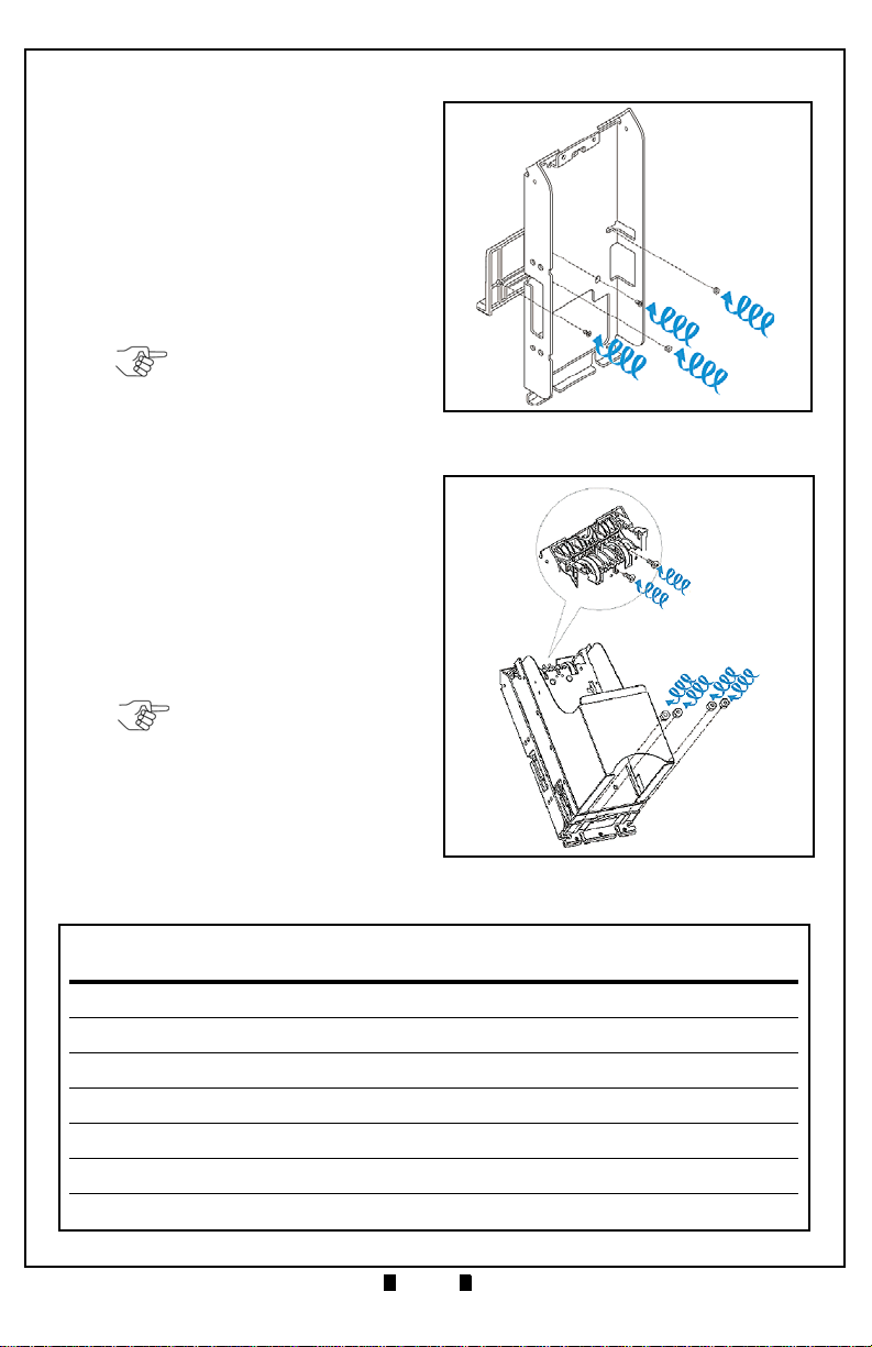
Installation................................................................................ 7
VEGA SH Unit...........................................................................................7
VEGA SU/SD Unit.....................................................................................7
VEGA SU/SD Unit (Continued 1)........................................................................8
VEGA SU/SD Unit (Continued 2)........................................................................9
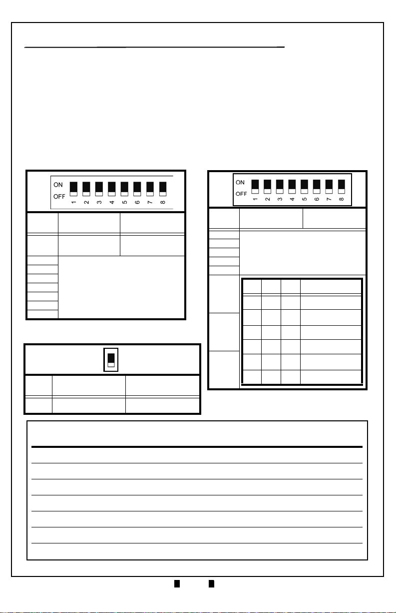
DIP Switch Settings............................................................... 10
Functional Testing...................................................................11
DIP Switch Test.......................................................................................11
Feed Motor Forward Rotation Test..........................................................11
Feed Motor Reverse Rotation Test .........................................................12
Stacker Motor Test ..................................................................................12
Aging Test ...............................................................................................13
Sensor Test.............................................................................................13
Sensor Test (Continued) ...................................................................................14
Software Download Procedure.............................................. 15
Software Download Procedure (Continued 1).........................................16
Software Download Procedure (Continued 2).........................................17
Non-PC Calibration Procedures ............................................ 18
Non-PC Calibration Procedures (Continued)..........................................19
Off-Line Banknote Acceptance Test........................................................20
Error and Reject Code Tables..........................................................................20
Error and Reject Code Tables (Continued) ......................................................21
VEGA Parts List..................................................................... 22

Part No. 960-000165R_Rev. 1 © 2013, JCM American, Corporation
3
July, 2013 JCM Training Overview VEGA™ Banknote Acceptor
Lecture Notes
OVERVIEW
This training course addresses the following JCM VEGA™ device versions:
VEGA U
NIT
Figure 1 illustrates a typical VEGA Currency Validation Unit.
Table 1 Various VEGA Versions
Device Capacity/Contents
VEGA 100 12V DC Power (NO Magnetic Sensor)
VEGA 101 12V DC Power / Magnetic Sensor (W)
VEGA 102 24V DC Power / NO Magnetic Sensor
VEGA 103 24V DC Power / Magnetic Sensor (J)
VEGA 104 24V DC Power / Magnetic Sensor (W)
VEGA 105 12V DC Power / Magnetic Sensor (J)
Figure 1 Typical VEGA Unit

Part No. 960-000165R_Rev. 1 © 2013, JCM American, Corporation
4
VEGA™ Banknote Acceptor JCM Training Overview July, 2013
Lecture Notes
VEGA FEATURES
The VEGA Unit contains the following features:
• Works as a stand-alone Bill Validator, or with optional equipment
• Combined with the RC-30, it provides a Banknote Recycling capability
• Accepts foreign and U.S. Banknotes 110-165 mm Long by 60-82 mm Wide
• The VEGA can be configured as an SH = Downward Horizontal Stacking,
SU = Upward Vertical Stacking, or SD = Downward Vertical Stacking Unit
• Communicates via Photo-coupler Isolation, RS232C, or ccTalk
• Validates Banknotes with an array of Optical (five wavelengths), and magnetic
Sensors
• Utilizes Standard (300 Banknotes) or Large (1000 Banknotes) Cash Box sizes
• Provides convenient four-way Banknote acceptance
• Full Color range Diagnostic LED's
• Adjustable Cash Box removal; Front or Rear (SH Type), Upward (SU or SD Type)
• Contains an Optical and Mechanical Anti-stringing Mechanism
• 95% or greater Banknote acceptance (including the 1st Banknote returned and 2nd
Banknote accepted).

Part No. 960-000165R_Rev. 1 © 2013, JCM American, Corporation
5
July, 2013 JCM Training Overview VEGA™ Banknote Acceptor
Lecture Notes
USER PRECAUTIONS
The following User precautions should be observed when installing, operating
and servicing a VEGA Unit:
• When closing the Upper portion of the Transport path or the Course Path Reversing
Guide Cover, ensure that it clicks firmly into place
• Turn the VEGA's Power OFF when opening the Upper Section of the Lower
Guide; otherwise, the Rollers may begin operating and personal injury to fingers
may occur by having them pulled into the Unit
• Be careful to avoid personal injury to your fingers when closing the Upper Guide
Section
• Clean the VEGA Unit once a Month to keep its performance stable and avoid
degraded Banknote acceptance
• Use a lint-free cloth or Cotton Swabs to carefully remove dirt on the Sensors, and
to remove any Paper powder dust adhering to the Rollers
• Under no circumstances allow a cleaning cloth to be wet enough to allow excess
fluid to run into the device; internal Printed Circuit Boards may be damaged. Do
not use Alcohol, citrus based cleaners, solvents or scouring agents that can damage
the plastic surfaces of the device
• Do not re-design or disassemble the VEGA Validator. Unauthorized use by inade-
quately trained personnel, or use outside the original Manufacturer's intent for
operation voids the warranty
• Do not inject water or liquid agents of any kind into the Validator; as this may cause
extreme damage to the Unit.

Part No. 960-000165R_Rev. 1 © 2013, JCM American, Corporation
6
Lecture Notes
VEGA™ Banknote Acceptor JCM Training Overview July, 2013
COMPONENT LOCATIONS
Component Names
Figure 2 illustrates the VEGA Component Names and Locations.
e
a) Upper Section
b) Bezel
c) Upper Section Open/Close Buttons
d) Cash Box
e) USB Connector Receptacle Cover
f) Interface Connector Receptacle
g) Recycler (RC) Connector Receptacle
h) DIP Switches
i) Course Path Reversing Guide
j) Course Path Reversing Guide Cover
Release Buttons
k) Cash Box Door
l) Thumb Lock Knob
m) Banknote Insertion Slot
n) Frame Lock (Option)
a
b
c
d
gf
h
j
l
k
im
n
Left Side Right Side
BottomTop
Back Side Front Side
Figure 2 VEGA Component Names

Part No. 960-000165R_Rev. 1 © 2013, JCM American, Corporation
7
July, 2013 JCM Training Overview VEGA™ Banknote Acceptor
Lecture Notes
INSTALLATION
VEGA SH U
NIT
Perform the following steps to install a VEGA SH Unit into a Host Machine:
1. Mount the VEGA SH Unit in place without the Cash Box installed.
2. Bolt the bottom of the VEGA Frame
into place using four (4) M4 Hex-
nuts (See Figure 3 a1, a2, a3 & a4).
3. Set the VEGA DIP Switches to On-
line Mode (Refer to "DIP Switch
Settings" on page 10 of this Guide).
4. Connect the VEGA Unit to the Host
Machine using the User supplied
harness.
5. Apply power to the VEGA Unit.
6. Activate the VEGA Unit normally,
and confirm that the LED lighting
sequence indicates an active idle mode Color pattern as set by DIP Switch selec-
tion.
VEGA SU/SD U
NIT
Perform the following steps to install a VEGA SU/SD Unit into a Host
Machine.
1. Set the VEGA DIP Switches to On-line Mode (Refer to "DIP Switch Settings" on
page 10 of this Guide).
2. Connect the VEGA to the Host Machine using a User supplied Harness.
3. Apply power to the VEGA Unit.
4. Activate the VEGA Unit normally, and confirm that the LED lighting sequence
indicates an active Idle Mode Color pattern as set by DIP Switch selection.
5. Turn the VEGA Unit's power OFF and disconnect the Harness between the
VEGA and the Host Machine.
Figure 3 M4 Nut and DIP Switch
Locations
b
a1a2
a3
a4
NOTE: The bolt lengths are not
to extend more than 5mm up
from the ground plane.
NOTE: Refer to Figure 3b to
locate the DIP Switches on the
VEGA Unit.

Part No. 960-000165R_Rev. 1 © 2013, JCM American, Corporation
8
Lecture Notes
VEGA™ Banknote Acceptor JCM Training Overview July, 2013
VEGA SU/SD Unit (Continued 1)
6. Connect the attached Bezel Plate
(See Figure 4 a) on the VEGA SD/
SU Bracket (See Figure 4 b) using
two (2) M4 screws (See Figure 4 c1
& c2).
7. Mount the VEGA SD/SU Bracket
into place on the Host Machine
using two (2) M4 Hexnuts
(See Figure 4 d1& d2).
8. Remove the Course Path Reversing
Guide and bolt the VEGA SD/SU
Unit into the VEGA SD/SU
Bracket on the Host Machine using
two (2) M4 Screws (See Figure 5 a1
& a2) and two (2) or four (4) M4
Hexnuts (See Figure 5 b1, b2,b3, &
b4).
9. Seat the Cash Box (See Figure 6 a)
into the frame and replace the
Course Path Reversing Guide cover
on the Upper Section (See Figure 6
b).
Figure 4 M4 Nut and DIP Switch
Locations
ba
c2
c1
d2
d1
NOTE: The bolt lengths should
not extend more than 15mm
upward from the Host Machines
base.
Figure 5 M4 Screw and Nut Locations
a1
a2
b1b3b4
b2
NOTE: The number of Screws
required depends on each Host
Machine's specification
requirements.

Part No. 960-000165R_Rev. 1 © 2013, JCM American, Corporation
10
Lecture Notes
VEGA™ Banknote Acceptor JCM Training Overview July, 2013
DIP SWITCH SETTINGS
The VEGA Banknote Validator contains three (3) DIP Switch Blocks (i.e.,
DS1, DS2, and DS3). They are located in the center of the top of the Unit
approximately two (2) inches from the front of the Unit (Review Figure 2 h).
• DIP Switch Block DS1 is used to select Test Mode, and to select the desired
Banknote Acceptance/Inhibit settings shown in Table 2.
• DIP Switch Block DS2 is used to select between the desired Communications
Interface Protocols shown in Table 3.
• DIP Switch Block DS3 selects between the RS232C and Pulse Interface Com-
munication Protocols shown in Table 4.
Table 4 DIP Switch Block 3 Settings
Switch
No. Switch ON Switch OFF
1 RS232C Interface Pulse Interface
Table 2 DIP Switch Block 1 Settings
Switch
No. Switch ON Switch OFF
1Test Mode Basic
Performance
2
Refer to the Related Country’s
Software Specification Sheet
3
4
5
6
7
8
DS1
Table 3 DIP Switch Block 2 Settings
Switch
No. Switch ON Switch OFF
1
Refer to the Related Country’s
Software Specification Sheet
2
3
4
5
6
7
8
DS2
6 7 8 IF Setting
OFF OFF OFF ID-003 Serial (RS-232C)
OFF ON ON ID-003 (Photo-Coupler
Isolation)
OFF ON OFF ccTalk (Non-Encrypted)
ON ON OFF ccTalk (Encrypted)
ON OFF ON ccTalk (Simple
Checksum)
ON OFF OFF MDB
DS3
1 (ON)
2 (OFF)

Part No. 960-000165R_Rev. 1 © 2013, JCM American, Corporation
11
July, 2013 JCM Training Overview VEGA™ Banknote Acceptor
Lecture Notes
FUNCTIONAL TESTING
DIP S
WITCH
T
EST
Perform the following steps to test the functionality of each DIP Switch Block:
1. Ensure that the VEGA's Power is OFF.
2. Set all DIP Switches on DS 1 and DS 2 to the ON position.
3. Apply Power to the VEGA.
4. Set DS 1, Switch #1 to OFF. The Front Panel LED will go out (Extinguish).
5. Set DS 1 Switches #3, #5, & #7 and DS 2 Switches #1, #3, #5, & #7 to OFF.
The Front Panel LED will blink at a Yellow Color Rate.
6. Set DS1 and DS2 Switches #2, #4, #6, & #8 to OFF. The Front Panel LED will
blink at a Blue Color Rate if all the DIP Switches function properly.
F
EED
M
OTOR
F
ORWARD
R
OTATION
T
EST
Perform the following steps to test the normal forward rotation functionality of
the Feed Motor:
1. Ensure the VEGA's Power is OFF.
2. Set DS1, Switch #1 ON.
3. Apply Power to the VEGA.
4. Set DS1, Switch #1 OFF. This begins the Feed Motor Forward Rotation Test.
5. If the Feed Motor correctly rotates forward, the Front Panel LED will remain
extinguished (Out) and forward rotation will continue.
6. To end the Test, Set DS 1 Switch #1 to ON.
Table 5 Transport Motor Abnormal Error Codes
LED Color Blink Sequence Error Indication
White 3Feed Motor Low Speed Problem
5 Feed Motor High Speed Problem
7 Feed Motor Lock-up Problem
NOTE: If the Front Panel LED blinks any White sequence in Table 5, the Feed
Motor Forward Rotation is abnormal.

Part No. 960-000165R_Rev. 1 © 2013, JCM American, Corporation
12
Lecture Notes
VEGA™ Banknote Acceptor JCM Training Overview July, 2013
F
EED
M
OTOR
R
EVERSE
R
OTATION
T
EST
Perform the following steps to test the normal reverse rotation functionality of
the Feed Motor:
1. Ensure the VEGA's Power is OFF.
2. Set DS1, Switches #1, & #2 ON.
3. Apply Power to the VEGA.
4. Set DS1, Switch #1 OFF. This begins the Feed Motor Reverse Rotation Test.
5. If the Feed Motor rotates in reverse correctly, the Front Panel LED will remain
extinguished (Out) and reverse rotation will continue.
6. To end the test, set DS1, Switch #1 ON.
S
TACKER
M
OTOR
T
EST
Perform the following steps to test the Stacker motor functionality:
1. Ensure the VEGA's Power is OFF.
2. Set DS1, Switches #1, & #3 ON.
3. Apply Power to the VEGA.
4. Set DS1, Switch #1 OFF. This begins the Stacker Motor Test.
5. If the Stacker Motor rotates correctly, the Front Panel LED will remain extin-
guished (Out) and the Motor will continue operating.
6. To end the test, set DS1, Switch #1 ON.
Table 6 Stacker Motor Error Codes
LED Color Blink Sequence Error Indication
RED 5 Cash Box Seating Problem
PURPLE 5 Stacker Motor Lock-up
7 Stacker Motor Gear Problem
ORANGE 3 Stacker Full
NOTE: If the Front Panel LED blinks any white sequence in Table 3, the Feed
Motor Reverse Rotation is abnormal.
NOTE: If the Front Panel LED blinks any error sequence listed in Table 6, the
Stacker Motor's Rotation is abnormal.

Part No. 960-000165R_Rev. 1 © 2013, JCM American, Corporation
13
July, 2013 JCM Training Overview VEGA™ Banknote Acceptor
Lecture Notes
A
GING
T
EST
Perform the following steps to repeatedly test the VEGA's basic feeding, trans-
porting, and stacking functions:
1. Ensure the VEGA's power is OFF.
2. Set DS1, Switches #1, #2 & #4 ON.
3. Apply power to the VEGA.
4. Set DS1, Switch #1 OFF. This begins the Aging Test.
5. If operation is normal, the Unit will perform the following five functions repeti-
tively:
a. Feed Motor Reverse Rotation
b. Interval Test (20 sec. LED Lights White)
c. Feed Motor Forward Rotation
d. Stacking Test
e. Interval Test (20 sec. LED Lights White).
6. To end the test, set DS1, Switch #1 ON.
S
ENSOR
T
EST
Perform the following steps to verify if the eight (8) Sensors within the VEGA
are functional:
1. Ensure the VEGA's power is OFF.
2. Set DS1, Switches #1, #2, #3, #4 & #5 ON.
3. Apply power to the VEGA.
4. Set DS1, Switch #1 OFF. This begins the Sensor Test.
Table 7 Stacker Motor Error Codes
LED Color Blink Sequence Error Indication
WHITE 3 Feed Motor Low Speed Problem
5 Feed Motor High Speed Problem
7 Feed Motor Lock-Up
RED 5 Cash Box Seating Problem
PURPLE 5 Stacker Motor Lock-up
7 Stacker Motor Gear Problem
ORANGE 3 Stacker Full
NOTE: If the Front Panel LED blinks any error sequence listed in Table 7, the
Stacker Motor's Rotation is abnormal.

Part No. 960-000165R_Rev. 1 © 2013, JCM American, Corporation
14
VEGA™ Banknote Acceptor JCM Training Overview July, 2013
Lecture Notes
Sensor Test (Continued)
Table 8 lists the DS2 settings for the Sensor Test configuration. Select the
intended Sensor from the Table, and set the DS2 Switches according to the
Table Switch positions.
5. When the selected Sensor detects an object, the Front Panel LED Display will
blink at a Yellow Color Rate. Otherwise, the Front Panel LED will be extin-
guished (Out).
Table 8 DIP Switch Block DS2 Sensor Configuration Settings
DIP Switch Block DS2 Yellow LED State
Sensor 12345678 Lit Extinguished
Entrance Sensor ON OFF OFF OFF OFF OFF OFF OFF With Paper (Light
Interception) No Paper
(Transmissive)
Validation Sensor OFF ON OFF OFF OFF OFF OFF OFF With Paper (Light
Interception) No Paper
(Transmissive)
Side Sensor OFF OFF ON OFF OFF OFF OFF OFF With Paper (Light
Interception) No Paper
(Transmissive)
Escrow Sensor OFF OFF OFF ON OFF OFF OFF OFF With Paper (Light
Interception) No Paper
(Transmissive)
RC Flap Sensor OFF OFF OFF OFF ON OFF OFF OFF With Paper
(Transmissive) No Paper (Light
Interception)
Stacker Flap
Sensor OFF OFF OFF OFF OFF ON OFF OFF With Paper
(Transmissive) No Paper (Light
Interception)
Stack-In Sensor OFF OFF OFF OFF OFF OFF ON OFF With Paper (Light
Interception) No Paper
(Transmissive)
Box Sensor OFF OFF OFF OFF OFF OFF OFF ON With Paper (Light
Interception) No Paper
(Transmissive)

Part No. 960-000165R_Rev. 1 © 2013, JCM American, Corporation
15
July, 2013 JCM Training Overview VEGA™ Banknote Acceptor
Lecture Notes
SOFTWARE DOWNLOAD PROCEDURE
Perform the following steps to download the VEGA Operating Software
Program (Refer to Figure 7 for the Tool Requirements and Harness Connector
locations).
However, before downloading the
VEGA Software Program, copy the
Downloader Program (UBA Down-
loader Version 2.10: specified), and
the VEGA Operating Software Pro-
gram into a VEGA Folder
([C:\VEGA]) created on the PC.
1. Turn Power to the VEGA Unit
OFF.
2. Set DS 1, Switches #1, #7, & #8
ON.
3. Apply Power to the VEGA Unit.
4. Confirm that the Front Panel
LED blinks at a Green Color
Rate.
5. Launch the copied Downloader
Program (UBA Downloader
2.10: Specified) from the PC
VEGA Folder ([C:\VEGA]).
The Program Installation Screen
shown in Figure 8 will appear.
Figure 7 Tools and Harness
Connection
a
e1
b, c & d
e
e2
h
g
f
Interface
Connector
Power Supply
To AC
VEGA USB
Connector
To PC USB Port
Power
a) PC (OS: Windows XP)
b) VEGA USB Driver (usbser.sys &
usbvega.inf)
(For Windows XP)
c) Downloader (UBA Downloader
Version2.10: Specified)
d) VEGA Software Program
e) USB Cable
e1) USB A Terminal
e2) USB Mini-B Terminal
f) VEGA Unit
g) Harness
h) Power Supply (e.g., UAC, VM-VEGA, etc.).
NOTE: DIP Switch Block No.
2 and No. 3 settings are not
required for this Software
Download

Part No. 960-000165R_Rev. 1 © 2013, JCM American, Corporation
16
Lecture Notes
VEGA™ Banknote Acceptor JCM Training Overview July, 2013
S
OFTWARE
D
OWNLOAD
P
ROCEDURE
(C
ONTINUED
1)
6. Mouse-click the "Browse"
Screen Button (See Figure 8
a) and select the desired
VEGA Software for down-
load into the VEGA Flash
Memory; then,
7. Mouse-click on the "Open"
Screen Button (See Figure 9
a) to launch the selected
file.
8. When the UBA Down-
loader Screen re-appears,
Mouse-click on the Center
"Download" Screen Button
(Review Figure 8 d) to
begin the Software down-
load into the VEGA Flash
Memory (See Figure 10 a).
The Downloading Screen
will display a Progress
Barograph during the down-
load operation (See Figure
10 b).
Figure 8 UBA Downloader Screen
a
db
c
Figure 9 UBA Downloader File Select
Screen
Selected File
a
NOTE: The Front Panel LED lights Yellow during a download.

Part No. 960-000165R_Rev. 1 © 2013, JCM American, Corporation
17
July, 2013 JCM Training Overview VEGA™ Banknote Acceptor
Lecture Notes
S
OFTWARE
D
OWNLOAD
P
ROCEDURE
(C
ONTINUED
2)
9. Once the download is com-
plete, the Front Panel LED
Display turns a steady Blue
Color, and then the VEGA
returns to a Start-up Process
condition (e.g., the Front
Panel LED Display blinks
at a Green Color rate).
10.When the download is com-
plete, confirm that the
Host's Checksum and the
Device's Checksums match
each other
(e.g. [CRC:XXXX = CRC:XXXX]).
11.After verifying a CRC match between both Checksums, Mouse-click on the
"OK" Dialog Screen Button to close the UBA Downloader Program Screen.
Figure 10 UBA Downloader Progress Bar
Screen
a
b
NOTE: If the Host and the Device CRC Checksums do not match, the download
did not end correctly. Confirm that the download procedure is correct, and re-
perform the download procedure again.
NOTE: If the word "Manual" appears in the "Reset" Pull-down Menu (Review
Figure 8 b); the Front Panel LED will sustain a steady Blue Color. In this case,
Return to the Start-up condition by pressing the adjacent "Manual reset" Screen
Button (Review Figure 8 c) located to the right of the pull-down Menu (The Front
Panel LED will then blink at a Green Color Rate).
NOTE: If a download error occurs, the Front Panel LED will light a Red Color.

Part No. 960-000165R_Rev. 1 © 2013, JCM American, Corporation
18
Lecture Notes
VEGA™ Banknote Acceptor JCM Training Overview July, 2013
NON-PC CALIBRATION PROCEDURES
When removing or replacing the Sensor, Sub-Sensor, or CPU Board, perform
the following steps to calibrate the Entrance, Validation, and Edge Sensors of
the VEGA Unit.
1. Figure 11 illustrates the Calibra-
tion connection Tools and Har-
ness configurations necessary
when calibrating WITHOUT
using a PC.
2. Set DS 1, Switches #1, #2, & #8
to ON. Ensure ALL DS 2
Switches are OFF.
3. Apply power to the VEGA and
the Front Panel LED will blink
Green.
4. Set DS 1, Switch #1 OFF.
5. The Front Panel LED will now
slowly blink at a Cyan Color
rate.
6. Set DS 2, Switch #1 ON.
This action begins the Entrance Sensor's Adjustment Procedure without
Reference Paper in Place.
7. The Front Panel LED will slowly blink at a White Color Rate once the Entrance
Sensor's adjustment is complete.
NOTE: If any of the Sensors are dirty the calibration will not be
accurate. Be sure to clean all the Sensors before calibrating
the Unit.
NOTE: There are two types of Calibration Procedures:
• Calibration using a PC, and
• Calibration without using a PC.
To calibrate using a PC, refer to the VEGA Operation and
Maintenance Manual, Section 6, Page 6-6.
Figure 11 Non-PC Calibration Tools
and Cabling
a
e
d
b
Interface Connector
Power Supply
To AC
Receptacle
Power
c
a) VEGA Unit
b) Power Supply (e.g., UAC, VM-VEGA, etc.)
c) Harness
d) White Reference Paper KS-325 (Part#
190876)
e) Black Reference Paper KS-326 (Part #
190875).
NOTE: Do not touch the
VEGA Unit while it's adjusting.
NOTE: Keep DS 2 Switches ON until instructed to turn them OFF.

Part No. 960-000165R_Rev. 1 © 2013, JCM American, Corporation
19
July, 2013 JCM Training Overview VEGA™ Banknote Acceptor
Lecture Notes
N
ON
-PC C
ALIBRATION
P
ROCEDURES
(C
ONTINUED
)
8. Set the White Reference Paper in place.
9. Set DS 2, Switch #2 to ON to begin the Validation Sensor Adjustment.
10.The White Reference Paper Adjustment is complete when the Front Panel LED
blinks at a Blue Color Rate.
11.Remove the White Reference Paper.
12.Set the Black Reference Paper.
13.Set DS 2, Switch #3 to ON to begin the Validation Sensor's Adjustment with the
Black Reference Paper.
14.The Black Reference Paper adjustment is complete when the Front Panel LED
blinks at a Purple Color Rate.
15.Remove the Black Reference Paper.
16.Set DS 2, Switch #4 to ON to re-perform the Validation Sensor's Non-paper
adjustment.
17.The Validation Sensor's Non-paper adjustment is complete when the Front Panel
LED blinks at a Green Color Rate.
18.Set DS 2, Switch #5 to ON to begin the Edge Sensor's Non-paper Adjustment.
19.The Edge Sensor's Non-paper Adjustment is complete when the front Panel
LED blinks at a Yellow Color Rate.
20.Set DS 2, Switches #1, #2, #3, #4, & #5 OFF in order to write these adjustments
into the VEGA's EEPROM Memory.
21.The adjustments are successfully written into the Memory when the Front Panel
LED blinks at a Green Color Rate.
22.Remove power from the VEGA Unit.
Table 9 Sensor Adjustment Error Conditions
LED Color Blink Sequence Error Indication
RED
1 Blink The Entrance Sensor adjustment has failed.
2 Blinks The Entrance Sensor adjustment using White Reference Paper
has failed.
3 Blinks The Validation Sensor adjustment using Black Reference Paper
has failed.
4 Blinks The Validation Sensor’s Non-Paper adjustment has failed.
5 Blinks The Edge Sensor adjustment has failed.
6 Blinks The EEPROM data writing process has failed.
NOTE: If the adjustment of any Sensor fails, the Front Panel LED will blink Red.
See Table 9 for Error Indications.

Part No. 960-000165R_Rev. 1 © 2013, JCM American, Corporation
20
Lecture Notes
VEGA™ Banknote Acceptor JCM Training Overview July, 2013
O
FF
-L
INE
B
ANKNOTE
A
CCEPTANCE
T
EST
Perform the following steps to perform the VEGA's Off-Line Banknote
Acceptance Test.
1. Ensure the VEGA's power is OFF.
2. Set DS1, Switches #1, #3 & #5 ON.
3. Apply power to the VEGA.
4. Set DS1, Switch #1 OFF. This begins the Off-line Banknote Acceptance Test.
Wait for the Front Panel LED to indicate Stand-by Mode, and then insert
Banknotes. Specific denominations are identified by Front Panel LED blink
sequences. Refer to the specific Country’s Software Information Sheet for
acceptable denomination value settings.
Error and Reject Code Tables
Table 10 lists the various VEGA Error Code LED combinations.
Table 10 LED Error Codes
On-Line Off-Line Error Possible Cause
Color Flashes
(mSec) Color Flashes
(mSec)
Yellow 1 (300) Yellow 1 (300) ROM Error ROM malfunction. Re-download Software. Change the CPU Circuit Board.
Yellow 2 (300)\ Yellow 2 (300) RAM Error RAM malfunction. Change the CPU CircuitBoard
Red 3 (300)\ White 3 (300) Feed Motor Low Speed During Feed Motor operation, no pulse input exists greater than the rated value.
Red 3 (300)\ White 5 (300) Feed Motor High Speed During Feed Motor operation, no pulse input exists greater than the rated value.
Red 3 (300)\ White 7 (300) Feed Motor Lock-up During Feed Motor operation, no pulse input exists greater than the rated value.
Red 3 (300)\ Purple 5 (300) Stacker Motor Lock-up During Stacker Motor operation, no pulse inputs exist greater that the rated value.
Red 3 (300)\ Purple 7 (300) Stacker Motor Gear Problem Pusher Mechanism stays in its home position while Stacker Motor is operating.
Red 3 (300)\ Blue 5 (300) Banknote Transport Slips An abnormal Banknote transport error occurs when transporting or rejecting
Banknotes.
Red 3 (300)\ Blue 7 (300) Transport Times Out Transportation locks-up or runs to slow.
Red 3 (300)\ Red 3 (300)\ Abnormal Timing Response Sensors detect Banknotes remain in-path or none exist during abnormal timing.
Red 3 (300)\ Red 5 (300)\ Cash Box Seating Cash Box Sensors detected a Banknote remains in-path or a Cash Box is not
properly seated
Red 3 (300)\ Purple 3 (300) Pusher Mechanism Position Pusher Mechanism Home Sensor detected that the Pusher Mechanism is not
presently seated at the Home end position.
Red 3 (300)\ Orange 3 (300) Stacker Full When the Pusher Mechanism moves toward stacking, the Stacker-Full Sensor
determined that the time taken is longer than the specified value for the function.
Red 3 (300)\ Cyan 3 (100) Operational Pause Intake Sensor detects a Banknote at a position where it cannot be returned while in
the transport process.
NOTE: If an Error or Reject condition occurs, refer to Table 10 or Table 11
respectively to identify the cause of the malfunction.
This manual suits for next models
5
Table of contents