JCM UAC™ Device Operator Guide September, 2016 JCM UAC™ Device Operator Guide September, 2016
Part No. 960-100194R_Rev. 3 © 2016 JCM American Corporation Part No. 960-100194R_Rev. 3 © 2016 JCM American Corporation
PART NUMBER CROSS REFERENCE
Table 4 provides a cross reference comparison list of UAC™ Part Descriptions
related to various JCM Products that are supported with the UAC™.
Table 4 Part Number Cross Reference List
JCMG
Part No.*
* JCMG Product Numbers beginning with the letter “G” designate products developed by
JCM-E Germany.
JAC
Part No.†
†JAC Product Numbers designate products developed by JCM American Corporation in the
USA.
Part Description
G00205 501-100218R UAC Module
G00286 ←Use EDP # DC Power Adaptor
Use JAC # →302-100007RA 2 Prong, USA AC Power Cord
Use JAC # →40i-000001R Harness Adapter, UBA to iVIZION
Use JAC # →302-000001R Harness, USB Cable Male A to mini B
G00262 40i-000026R Cable, Test Adapter, iVIZION/TBV
G00241 400-100669R Cable, Test Adapter, Vega ID-003
G00249 ←Use EDP # Cable, Test Adapter, Vega ID-0E3
G00599 ←Use EDP # Cable, Test Adapter, DBV-30x
G00388 ←Use EDP # Cable, Test Adapter, iPRO-RC ID-003/cc-Talk
G00183 302-200411R Cable, Test Adapter, Taiko ID-003
G00182 302-200410R Cable, Test Adapter, Taiko ID-0E2 cc-Talk
G00154 302-200409R Cable, Test Adapter, UBA/ WBA/iPRO
G00153 302-200404R Cable, Test Adapter, EBA-1x
G00054 302-200405R Cable, Test Adapter, EBA-03
G00055 302-200406R Cable, Test Adapter, EB-200
G00163 302-200407R Cable, Test Adapter, EBA-3x/EBA-40
G00289 ←Use EDP # Cable, Test Adapter, UBA-RC ID-003
Use JAC # →400-000158R Cable, Test Adapter, DBV-500
GA0012 ←Use EDP # Cable, Test Adapter, DBV-400
Use JAC # →960-100194R Manual, UAC Operators Guide
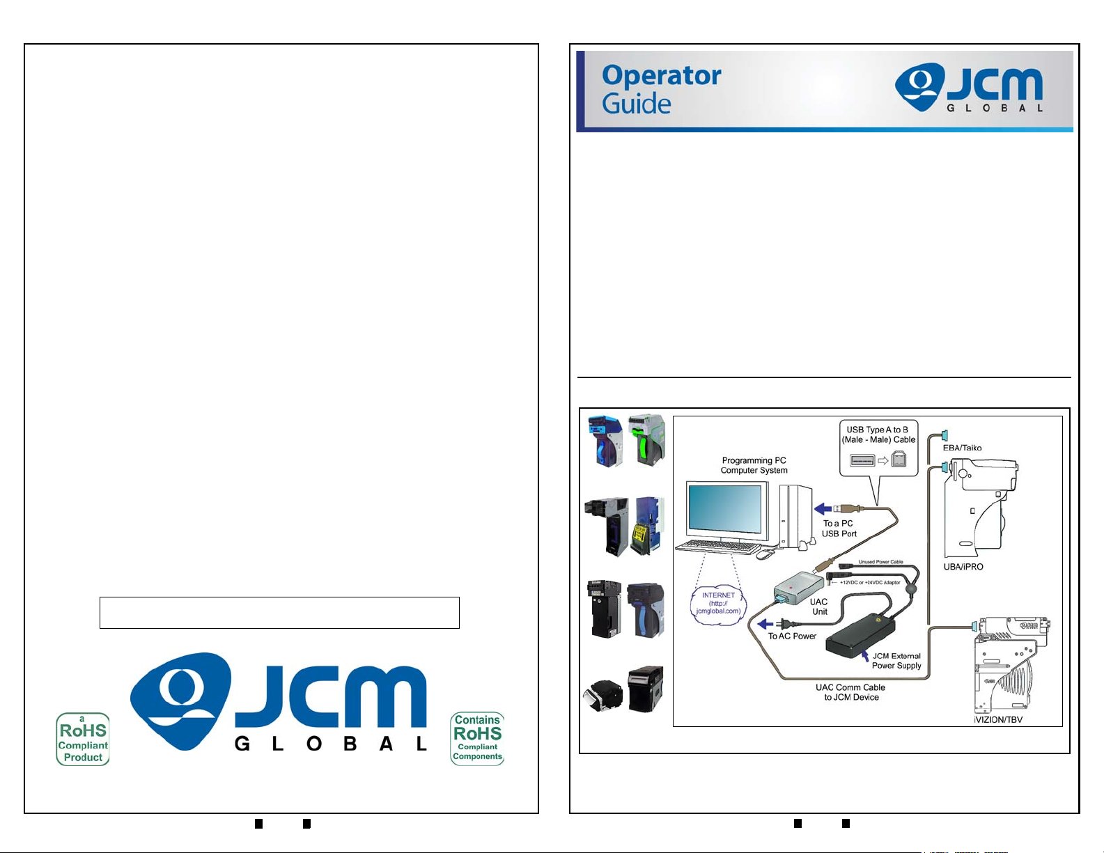
UAC DEVICE KIT PRIMARY COMPONENTS
Figure 2 illustrates the primary component parts of a typical JCM UAC™Kit.
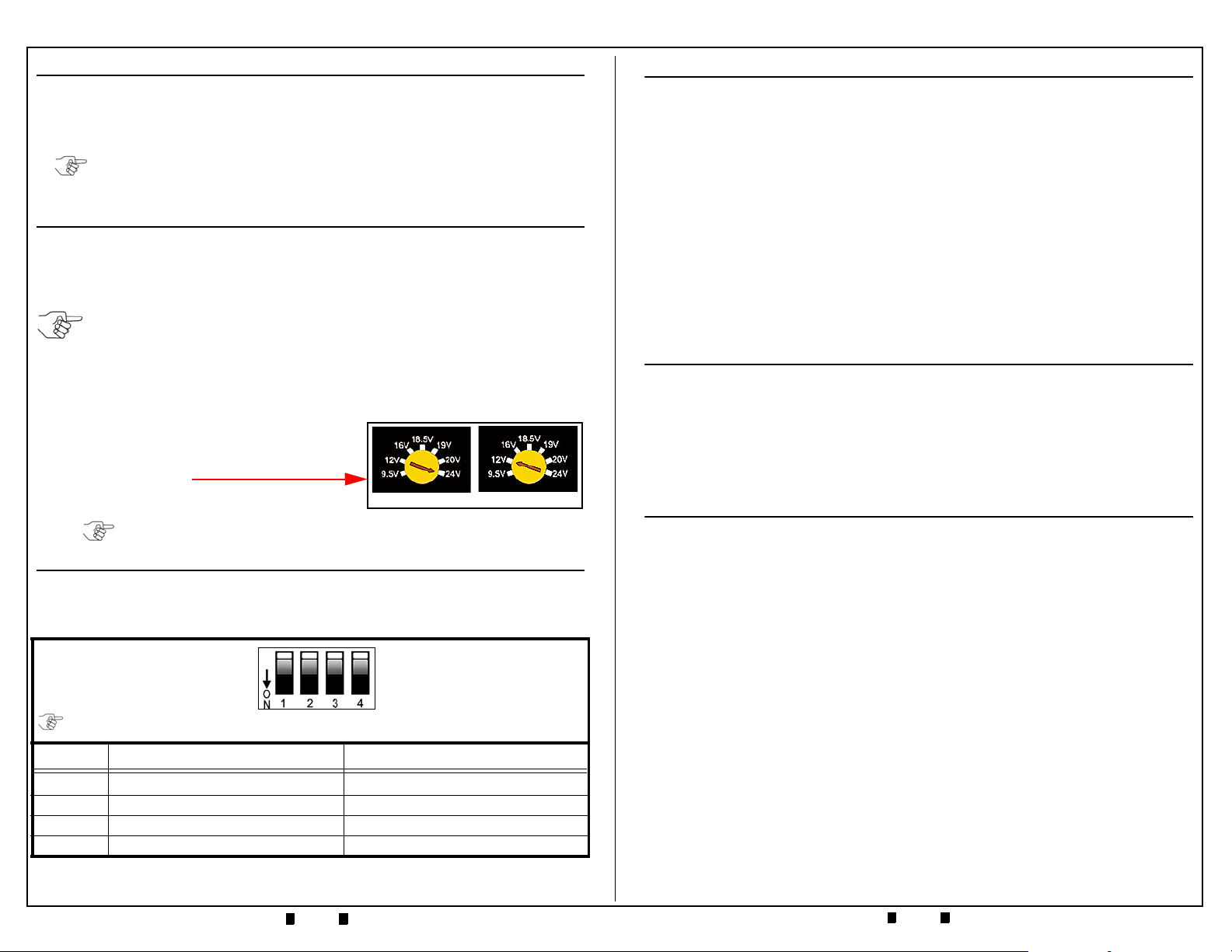
UAC CONNECTORS
Table 2 illustrates and lists the connector types found on the UAC™Device.
Table 2 UAC Connector Configurations
No. Connector Function Remark
1+12 VDC 3.5A or +24 VDC 3.0A Input from
Power Adaptor
Power Adaptor Input Voltage Range
= 110 to 240 VAC.
2
USB Type B Connector Jack
For USB Type A/B Cable connection
between the UAC and a PC USB
Jack.
3
Serial 9 Pin-D Connector
For the Serial 9 Pin-D Connector of a
Communications Cable to a
Banknote Acceptor’s Connector
(Cables can be ordered individually
for the Banknote Acceptor Model
desired).
Figure 2 Primary UAC Kit Component Parts
UAC Module
Selectable DC Output Power Adaptor
USB
Male A
to B
Cable
NOTE: Component photographs are for illustration
only, JCM may change part manufacturer or
style, based on availability.
UAC Communications Cable
(Cable will vary by Acceptor)
Power Adaptor AC Power Cord
DB-9 Output End DB-9 Pin Configuration
Pins as viewed
from connector side
Power & USB Input End USB-B Pin
Config
+DC
Input
Pin 1 = V Bus +5VDC
Pin 2 = D-
Pin 3 = D+
Pin 4 = Ground
Pin 1 = LED Anode
Pin 2 = Tx (RS232/TTL)
Pin 3 = Rx (RS232/TTL)
Pin 4 = GND
Pin 5 = +12VDC or +24VDC
Pin 6 = LED Cathode
Pin 7 = Tx (SEB-40x)
Pin 8 = Reserved
Pin 9 = Reserved