ROUBLESHOO ING
OPERATOR’S MANUAL FC-P30-UL
6.
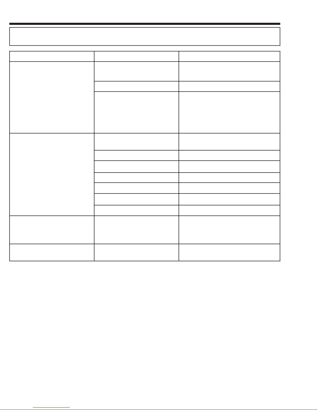
Pump is hard to turn or poor flow Filter is incorrect size for type of
fuel
Filter is clogged Replace filter
Loose filter Inspect and tighten
Replace with correct size filter 1 micron for
E85. 10 micron for gasoline, 30 micron for
diesel/kerosene
Pump is difficult to prime Hose not submerged in fuel when
trying to prime
Check hose and reposition hose in vehicle
fuel tank
Fuel level gauge does not work Float positioned diagonally across
tank
Remove red plastic nut and indicator cap.
Remove float mechanism and position so that
float is position across tank. Replace cap and
nut.
Ground wire is damaged or will not
clamp
Damaged Replace
Leak in hose fittings Check fittings and tighten
Vane sticking Check vanes for contamination
Excessive vane wear Check vanes for excessive wear and replace
Damaged, kinked, or cracked hose Replace with hose assembly
Inside of pump is dry or rusted from
extended periods of non-use
Remove pump out hose by loosening the 90°
elbow swivel fitting on top of pump. Spray
WD-40 or other light oil into the pump out
port. At the same time, turn handle in the
opposite direction of the arrow to lubricate
the pump. ust turn opposite direction of
arrow to prevent pumping fuel from tank.
Leak at fittings or pump mount Check fittings and tighten as required.
CONDI ION POSSIBLE CAUSE SOLU ION
OPERATOR’S MANUAL FC-P30-UL
3.
GENERAL PRODUCT DESCRIPTION
The Gas Caddy is designed and approved to safely transfer
fuel to and from a vehicle. It may be used to safely store fuel
during vehicle service. It is approved for use with unleaded
gasoline, diesel, kerosene, and E85 (ethanol) fuels.
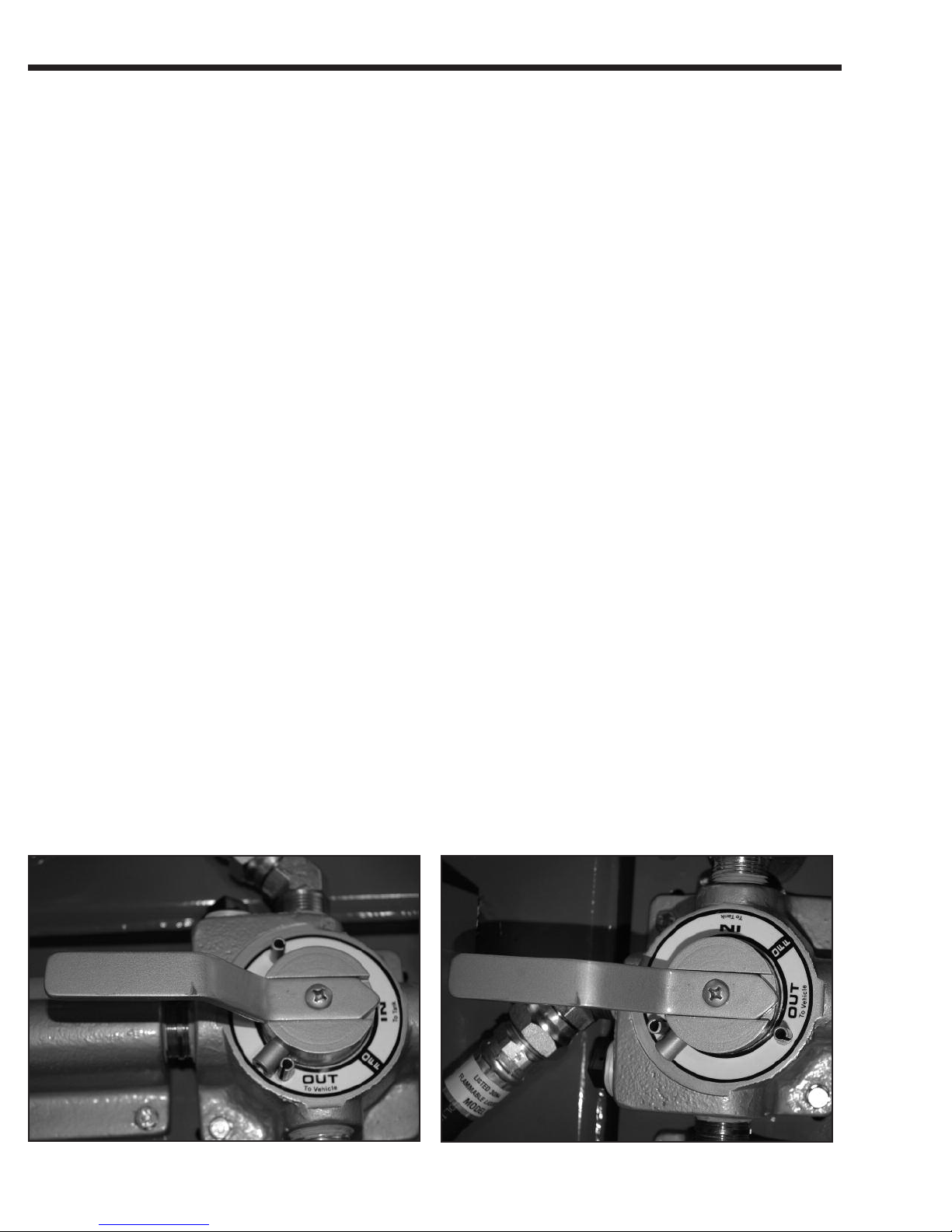
The direction of flow is controlled by a 4-way valve to assure
that fuel is filtered in both directions. Caution: urning the
pump in the opposite direction will pump the fuel, but this
will cause contaminates inside the filter to be introduced
into the fuel stream. Always use the valve to control the
direction of flow.
The FC-P30 comes standard with a 10 micron filter for use
with gasoline. Other filters are available for other fuels. Select
the correct filter for the intended application. Proper filter
selection is critical to achieving maximum pumping efficiency
and to properly remove contaminates from the fuel.
Refer to the table shown in REPLACE ENT PARTS AND
ACCESSORIES if you intend to pump different fuels.
Fuel Type Filter Type
Unleaded Gasoline 10 micron
Diesel and Kerosene 30 micron
E85 Ethanol 1 micron
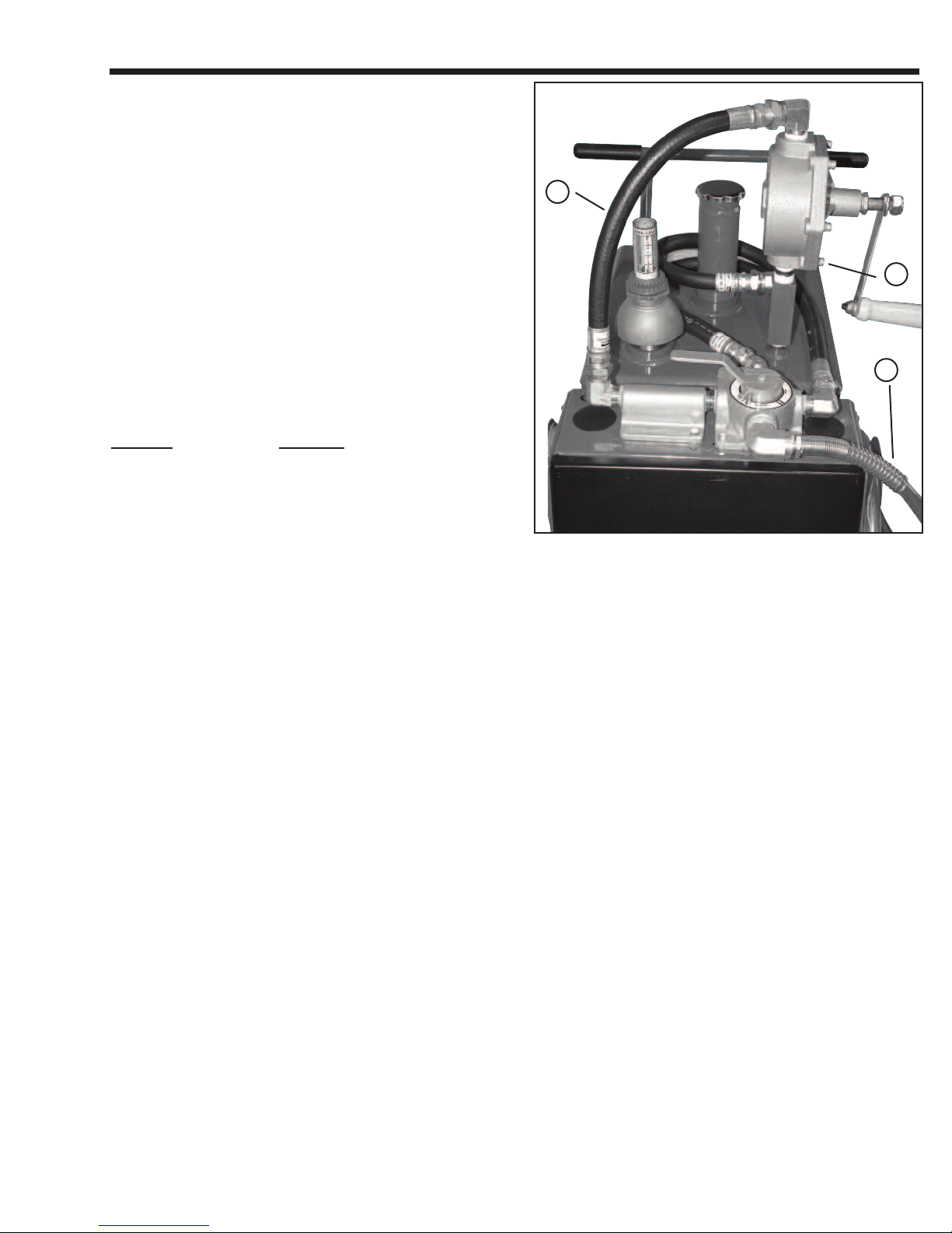
ASSEMBLY
1. Wrap 2 inch NPT thread on fill tube 4-6 wraps with PTFE
tape wrapping clockwise.
2. Assemble pump “A” onto tank by threading the “IN” side the
pump onto the 3/4 close nipple. Hold the manifold with a
1-1/2 inch adjustable wrench to prevent turning. Turn pump
until threads tighten with the final turn positioning the pump.
3. Position the handle to the left side of the tank as shown in
Figure 1.
4. Assemble the pressure hose “B” to the 90° swivel fitting on
top of the pump and to the 90° swivel fitting on the filter
support. Place a 1-1/16 inch open end wrench on the hose
and tighten the swivel using a 1-1/14 inch open end wrench.
Tighten securely to prevent leaks. Note: when tight the swiv-
el will not rotate.
5. Assemble the discharge hose “C” by threading the 3/4 NPT
fitting into 90° fitting located on the front of the valve assem-
bly. Pace a 1-1/16 inch wrench on the hose and tighten.
Tighten with wrench.
6. Coil and hang the discharge hose on the hose hanger
bracket on the side of the tank.
7. Thread the 2 inch fill pipe and cap assembly onto the fitting
in the center of the tank. Tighten snugly by hand until secure.
Tools and Supplies (not included):
• TPFE tape • 1-1/2 inch open end wrench
• 1-1/16 inch open end wrench
• 1-1/4 inch open end wrench.
10. Remove tape from top of fuel gauge and install plastic
indicator cap and plastic nut onto float assembly. Align
indicator mark to point diagonally across tank so that float is
free to move full range. Tighten nut by hand to secure cap
and fuel gage.
Fig. 1
B
A
C