JEANTIL PR 2000 R GT User manual

1
INSTRUCTION MANUAL
07/2006
PLEASE READ CAREFULLY AND UNDERSTAND BEFORE USING THE
EQUIPMENT
Mounted straw blower
PR 2000 R
PR 2000 R GT
3-Point linkage
Semi-trailer straw blower
PR 2000 R
PR 2000 R GT
Rigid axle
JEANTIL
Rue de la Tertrais
ZI La Hautière BP1
35590 L’HERMITAGE France
Tel: 00 33 (0)2.99.64.04.04
Fax: 00 33 (0)2.99.64.19.56
Spares shop Tel: 00 33 (0)2.99.64.04.02

2
E-mail: [email protected] –internet Site: www.jeantil.com
1. Aim of the Instruction Manual
a) General
This manual concerns all users of the equipment and anyone tasked with
assembling, installing, operating, adjusting, servicing, repairing or transporting
the equipment and its accessories.
It contains practical information for the correct and safe operation, handling,
adjusting and maintenance of your equipment.
Read carefully and ensure you understand the content before using the
equipment. Comply with the instructions and the safety-related advice.
b) Warning symbols
This warning symbol identifies important advice that must be followed for
your safety. When you see this symbol, take care as there is a potential risk of injury;
read the advice that follows carefully and inform other users.
c) Retention
Always keep this manual within easy reach or at your place of work (or
operating site).
Pass it on to any other user, including if you lend or sell the equipment.
d) Contact details (S.A.V.)
JEANTIL
Rue de la Tertrais
ZI de La Hautière
35590 L’HERMITAGE – France
Tel: 00.33. (0)2.99.64.04.04
Fax: 00.33. (0)2.99.64.19.56
Spares shop Tel: 00.33. (0)2.99.64.04.02

3
e) Statement of compliance with the European ‘Equipment’ directive
(Directive N°98/37/EC)
and to any relevant transposition regulations
Te manufacturer: JEANTIL
Rue de la Tertrais
ZI de La Hautière
35590 L’HERMITAGE – France
DECLARES THAT THE EQUIPMENT manufactured by JEANTIL as designated
below:
PR 2000 R
PR 2000 R GT
SERIAL N°: ……………
COMPLIES WITH:
1. Labour regulations
2. The revised European equipment directive N°98/37/EC
3. Revised EMC directive (electromagnetic compatibility) N° 89/336 EC
4. Specific safety standards: NF /EN 703 (mixers, straw blowers, silage feeders)
5. General safety standards: NF/EN/ISO 12100-1
NF/EN/ISO 12100-2
NF/EN 294
NF/EN 349
NF U 02-001-ISO 4254/1
NF EN 1553
NF EN 811
SIGNED AT HERMITAGE (DATE)
NAME OF SIGNATORY: Philippe JEANTIL
SIGNATURES:

4
2. Contents
1. Aim of the Instruction Manual
p.2
a. General p.2
b. Warning symbols p.2
c. Retention p.2
d. Contact details (S.A.V.) p.2
e. Statement of compliance with the “Equipment” directive p.3
2.
Contents
p.4
3. Equipment identification
p.6
4. Standard operating conditions
p.7
a. Applications of the equipment p.7
b. Operator qualification p.7
c. Definition of work stations p.7
d. Environmental conditions p.7
e. Manufacturer’s and user’s responsibilities p.8
5. Technical characteristics
p.8
6. General safety rules
p.11
1) General p.11
2) Warnings / labels p.12
3) Coupling p.16
4) PTO / Drive shaft p.16
5) Clogging (or blockage of the equipment) p.17
6) Maintenance and repair p.17
6. a / General p.17
6. b / Welding operations p.18
6. c / Servicing the tyres p.18
6. d / Electrical servicing p.18
6. e / Hydraulic servicing p.19
6. f / Repair
p.19
7. Environmental protection
p.19
8. Fitting and installation
p.20
1- Attachment p.20
2- Drive shaft p.20
3- Hydraulics p.20
4- Electrical p.21
9. Adjustments and maintenance
p.22
1- 3-point attachment p.22
2- Attaching the electric control unit p.22
3- Universal chute p.23

5
4- Shredder p.24
5- Chain tension p.24
6- Shredder safety bolts p.25
7- Tyre pressures p.26
8- Lubrication p.26
9- Feed conveyor reducer gear p.26
10- Gearbox p.26
11-Hydraulic hoses p.27
10. Start up and operation
p.27
1- Loading p.27
2- Mulching p.29
3- Spreading using round wrapped bales of silage and hay p.31
11. Additional equipment information
p.32
1- Hydraulic flow divider for tractor flow rates exceeding 45 l / min. p.32
2- 1 m door extension p.32
3- Semi-trailer kit (axle-wheels + drawbar) p.32
12. Cleaning
p.33
13. List of technical documents
p.34
I. Supplier spare parts
p.34
II. JEANTIL spare parts
p.34

6
3. Equipment identification
Type
N° de
série
Année de
construction
P.T.A.C.
Réceptionné
Masses
maximales
admissibles
Anneau
Essieu 1
Essieu 2
kg
kg
kg
kg
20 kg
Essieu 3
35590 L'HERMITAGE - FRANCE
Ref: 892 770
Manufacturer’s plate to EC standards.
Never remove the manufacturer’s plate and the EC marking fixed
to the equipment.
NON

7
4. Standard operating conditions
a) Applications of the equipment:
1.
This equipment is intended exclusively for use in agricultural work off the public
highway, i.e.: loading, shredding, distributing products such as straw, silage, hay,
wrapped silage in the form of round or square bales, wrapped blocks of 0.30m short
straw silage.
2.
Any other use falls outside normal usage and is therefore forbidden.
3.
For all other uses, please contact the manufacturer.
b) Operator qualification:
1.
The equipment must only be used, maintained and repaired by trained operators; see
page 2 “Aim of the Instruction Manual”.
2.
Before using your equipment, familiarise yourself with all controls and their correct
operation.
3.
All users, prior to using the straw blower, must have carefully read this Manual, have
understood it and applied all the safety instructions. Once working, it will be too late to
do this.
c) Definition of work stations:
1.
The work station for the equipment is the tractor driver’s cab.
2.
Never leave the driver’s station when the engine of the tractor and the equipment are
operating.
3.
To access the work station, use the access devices provided by the manufacturer (ladder,
footholds).
d) Environmental conditions
1.
Never approach or remain in those areas that are dangerous when the equipment is in
operation.
2.
Adapt your speed and driving style to the terrain, roads and tracks; be alert and take
care!
3.
Do not operate vehicles on ground that slopes longitudinally or laterally where there is a
risk of tipping or overturning.
4.
Do not start or brake abruptly.
5.
Operate your equipment with sufficient light to ensure safety; use appropriate artificial
light if necessary (contact your dealer or mechanic).

8
e) Manufacturer’s and user’s responsibilities
1.
Follow all advice contained in this manual concerning levels of knowledge, installation
procedures, operation, adjustment, maintenance and repair.
2.
Only use spare parts and accessories that comply with the manufacturer’s
recommendations.
3.
Do not carry out any modifications yourself and do not allow others to modify your
equipment and its accessories (mechanical, electrical, hydraulic or pneumatic
characteristics) without requesting prior written approval from the manufacturer.
4.
Failure to comply with these requirements may make the machinery dangerous. The
manufacturer disclaims any responsibility if damage or injury arises from such action.
5. Technical characteristics
1 Dimensions of variants: Mounted
-FP MAX = maximum push force (daN)
-FT MAX = maximum tractive force (daN)
C.D.G
En charge maxi
3
rd
upper point
25 mm dia. shaft
MAX WEIGHT = Kg
daN
F.P. MAX
F.T.
MAX
daN
2 lower points 28 mm dia.
shaft
3-point linkage, Category 2
NFU 14-032 / ISO 730
C of G
at maximum load

9
Semi-trailer
2. Schéma de préhension et d’arrimage
FA MAX = Max force on drawbar eye (daN)
TYPE PR 2000 R
PR 2000 R GT
Capacity 2m
3
2m
3
Maximum mulching range 18m 18m
B: Overall length 2.70m 2.70m
A: Internal length of container, door closed 1.70m 1.70m
C: Internal length of container, door open 3.00m 3.00m
D: Internal width of container 1.35m 1.35m
E: Overall width 1.79m 1.79m
F: Width with chute folded 1.91m 1.91m
G: Width with chute deployed 2.04m 2.04m
H: Container internal height 1.10m 1.10m
I: Overall height, chute deployed 2.42m 2.42m
J: Overall height, chute folded 2.21m 2.21m
K: Minimum spreading height 1.22m 1.22m
L: Maximum spreading height 2.42m 2.42m
M: Length with draw bar 3.82m
3.82m
N: Width with wheels 2.00m
2,00m
Empty weight
Kg
Kg
MAXIMUM GROSS WEIGHT
Kg
Kg
F.A. MAX
daN
C of G
at maximum load
F.E. MAX
daN
Drawbar eye dia 50 mm ISO 5692 / DIN 9678
On axle hook or tractor strong point
Or,
TOWING YOKE on tractor coupling bar (check that the coupling bar will support FA
MAX)
MAX WEIGHT
Kg

10
2 Lifting and tie down diagram:
Mounted
Semi-trailer
ISO 3767-1 standard lifting point, symbol 7.29.
ISO 3767-1 standard attachment point, symbol 7.34.
C of G
C of G

11
6. General safety rules
1) General
1. Never forget that knowledge, awareness and caution are the best way to ensure your
safety.
2. Regulations and rules relating to accident prevention, health and safety at work, and the
operation of vehicles on the public highway must be observed at all times.
3. Chapter 4 (Standard operating conditions) of this Instruction Manual, contains basic
directives that must be followed for the sake of your safety.
4. Make sure that no person, animal or obstruction is located near the equipment before it
is set in motion and throughout its operation or any other manoeuvre.
5. Children must never be allowed near the equipment.
6. Never carry passengers on the equipment.
7. Do not step on the cowlings or on any other part of the equipment, apart from any areas
provided for this purpose (ladder, platform, and means of access to the work station).
8. Before carrying out any work on the equipment, ensure that it cannot be started up
accidentally.
9. All controls (cords, cables, push-rods, hoses, etc.) must be positioned in the locations
provided for them so that they cannot accidentally initiate a manoeuvre likely to cause
an accident or damage.
10. Before use, after any adjustment or maintenance, ensure that all protective devices are in
position and in good condition, and that their latches are engaged.
11. Before use, check tightness of screws, nuts, connectors and wheels. Retighten if
required.
12. Do not wear loose clothing, long untidy hair and jewellery that might get caught in the
moving parts of the equipment.
13. Keep your hands, arms and feet well away from any moving parts, even those that are
slow-moving. Keep well away from moving parts.
14. If you detect any unusual noise or vibration, shut down the equipment and identify and
eliminate the cause of the incident before resuming work. Contact your dealer if
required.
12
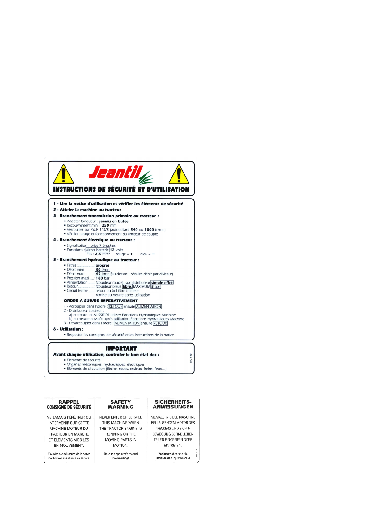
2) Warnings/Labels
1. Warnings and labels fixed to the equipment provide information about safety measures
to be taken that will contribute to the avoidance of accidents.
2. Make sure that these warnings and labels remain clean and legible. If they are damaged,
ask for new labels from the manufacturer (or agent).
3. If repairs are carried out, check that the replacement parts carry the same labels as those
that have been removed.
Ref: 892 640
Ref: 892 227
Ref: 892 230
Placed forward to R and L of the body
SAFETY AND OPERATING LABEL
CLEARLY mounted IN FULL VIEW on the
front of all items of equipment, close to those
components used to connect the unit to the
tractor.
13
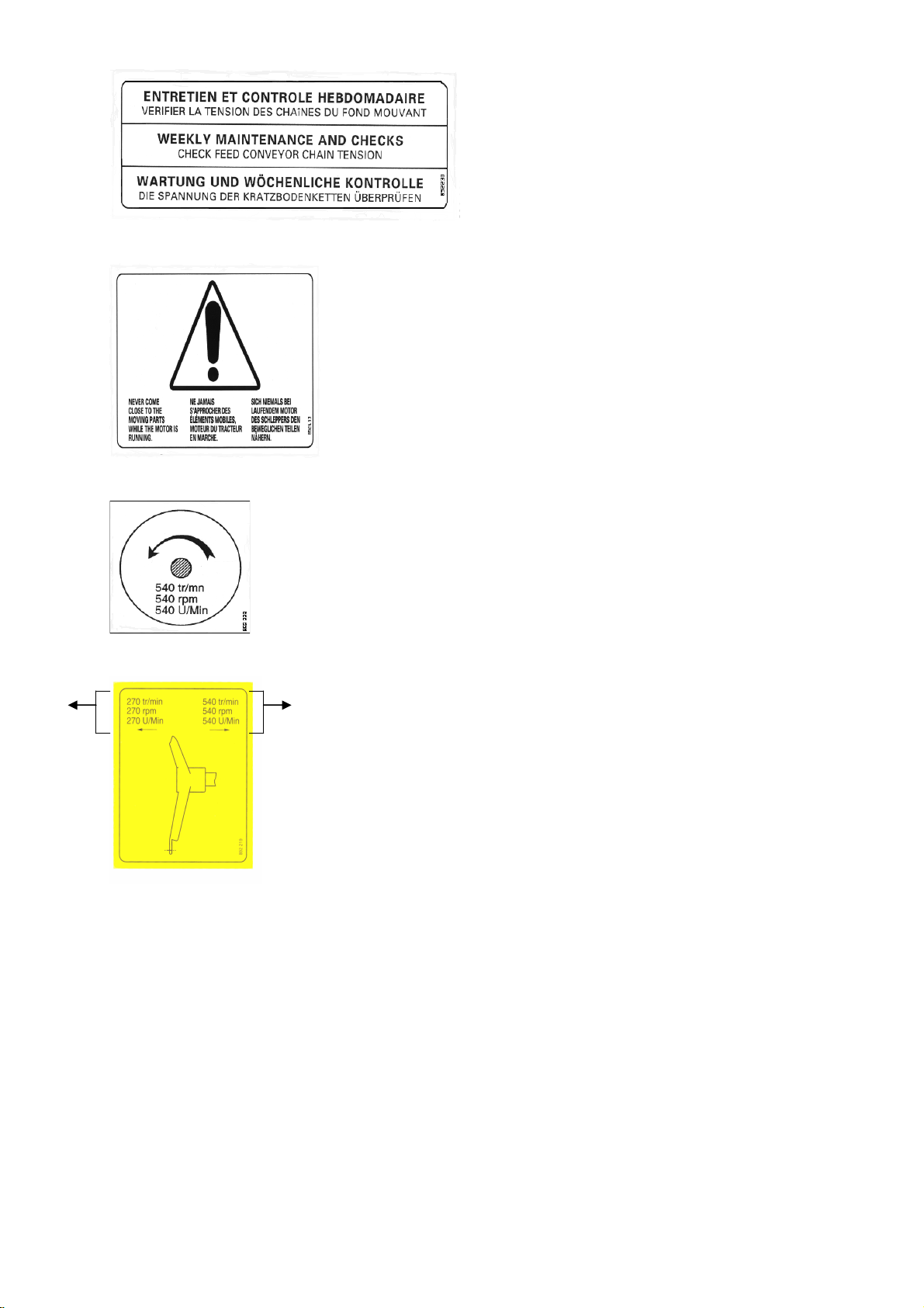
Ref: 892 453
Ref: 892 229
Ref: 892 219
Placed on the metal
casing of the drive shaft
Placed to the rear R and L
on the sides of the body,
and on the forward face of
the equipment
Placed low down R and L on the sides of the body
Placed on the metal casing of
the drive shaft
Spreading
and mixing Mulching
14
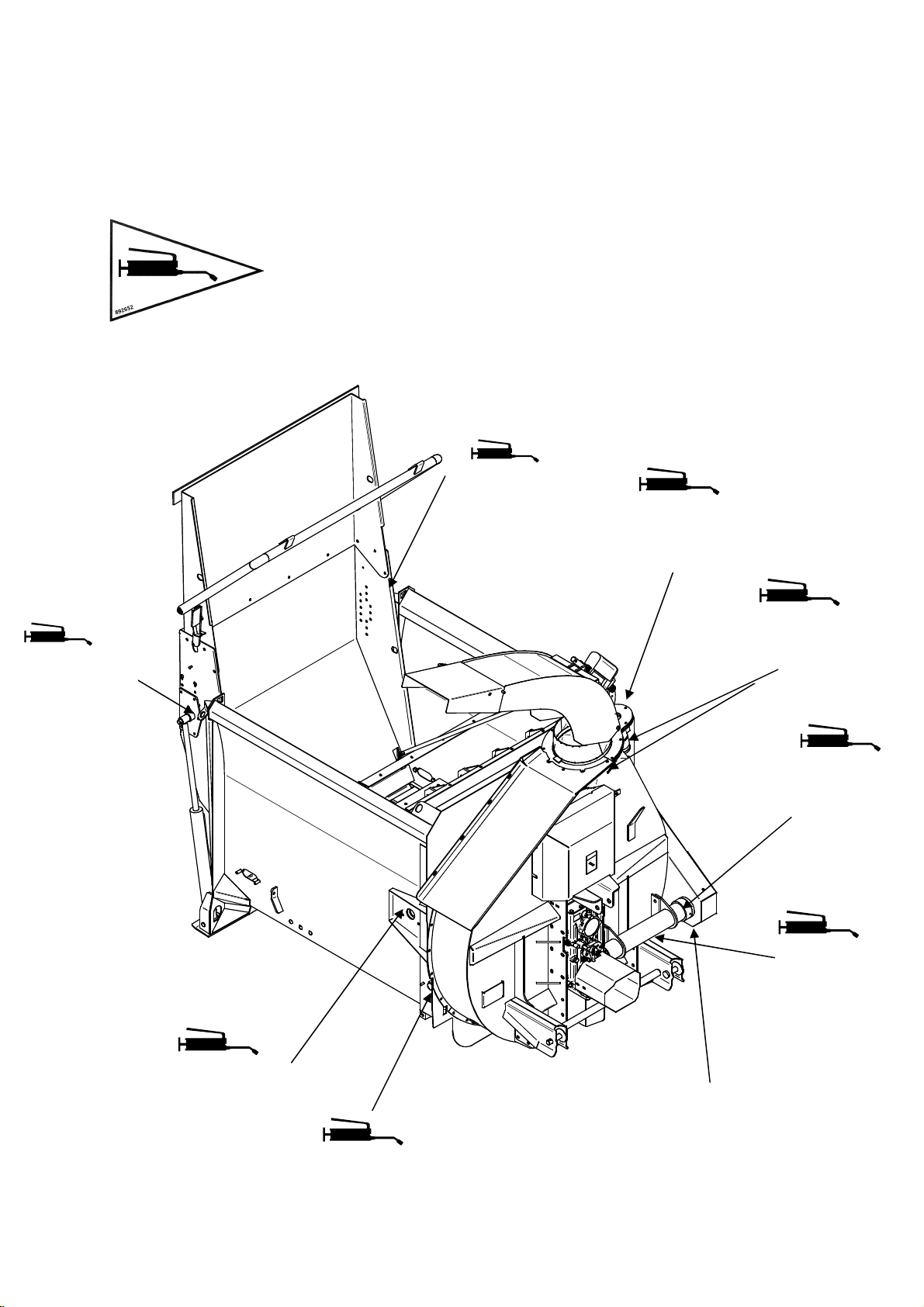
Lubrication chart
Ref: 892 652
Placed close the components to be greased
See diagram
Rotating
chute
greaser
Actuator
upper spindle
greaser
Shredder
bearing greaser
Feed conveyor
shaft bearing
greaser
Actuator
upper spindle
greaser
Gearbox
output shaft
greaser
Shredder
bearing
greaser
Feed conveyor
shaft bearing
greaser
The shredder drive chain is splash lubricated
from an oil bath inside its protective casing.
Unscrew the lower cover to check the oil level.

15
Operating stickers (depending on equipment and options) placed on the electrical control unit, located on
the forward face of the unit:
Standard Electrical regulator Electrical distributor
Standard Electrical regulator Electrical distributor

16
3) Coupling
1. See chapter 5, Technical characteristics, page 8.
2. Attaching the unit to the tractor must only be carried out using the tractor’s rear
coupling points provided for this purpose.
3. Check compatibility of the unit with the tractor (minimum engine power, type of
coupling, tractor PTO characteristics, etc.). Keep clear of the area between the tractor
and the unit until you have stopped the tractor’s engine and removed the starter key.
4. Keep clear of the area between the tractor and the unit during any operation of the
tractor linkage, whether this is being controlled from the cab or from outside the tractor.
5. When manoeuvring, select the lowest possible tractor gear ratio. When coupling, attach
the equipment’s electrical control unit in the tractor cab, ensuring that it cannot move
during the operation.
6. Once the equipment has been coupled up, the hitch must be locked. Check correct
locking and the condition of the coupling before any movement.
7. Check that the equipment’s coupling does not create either an overload or poor weight
distribution on the tractor that might compromise stability:
-Do not exceed the maximum allowed loading for the tractor and equipment
attachment points.
-Where necessary, fit ballast weights to the mounts provided for this purpose in
accordance with the tractor manufacturer’s recommendations.
Couple the unit to a tractor whose linkage is equipped with lateral and vertical locking
devices.
4) Power Take Off (PTO) / Drive shaft
1. Read and learn the manufacturer’s instructions for the drive shaft, attached to the
transmission.
2. Check that the PTO guards are fitted and in good condition. Replace them immediately
if damaged.
3. Adjust the length between the tractor and the unit, retaining maximum engagement.
4. Minimum engagement length is 250mm. See white instruction stickers fitted on the
front of the unit, n° 892 640 (page 10).
Before each operation, check that the drive shaft is in good condition and that it is fitted
and locked correctly.
5. Only use the drive shaft provided with the equipment or recommended by the
manufacturer.
6. Check before each use that the speed and rotational sense of the tractor PTO are
compatible with the planned usage of the equipment.

17
5) Clogging (or blockage of the equipment)
If the chute or turbine become blocked:
1. Declutch the tractor PTO.
2. Raise the chute to maximum.
3. Operate the feed conveyor in reverse to clear the inlet to the shredder and turbine.
4. Open the rear door.
5. Lower the straw blower fully to the ground.
6. Stop the tractor engine and remove the starter key.
7. Select the turbine gearbox to neutral.
8. Clear the chute by hand.
9. Check if the turbine blades are clogged; if necessary clear then by hand.
10. After cleaning, re-engage the turbine gearbox:
Low gear 270 rpm for spreading
High gear 540 rpm pour mulching
11. Enter the tractor cab.
12. Start the tractor.
13. Close the rear door.
14. Engage the tractor PTO while rotating the turbine at low rpm and accelerate up to a PTO
speed of 540 rpm.
15. Continue the operation that was interrupted, mulching or spreading.
16. If the blockage has not been cleared, repeat the operation from paragraph 1.
6) Maintenance and repair
6. a / General:
1. Maintenance and repair operations must only be carried out by qualified personnel.
2. Always maintain the equipment and its accessories in perfect working order to ensure
safe and efficient operation.
3. Check the cleanliness of the oil.
4. Respect maintenance periods.

18
Before any servicing or repair:
5. Check the stability of the unit and its components.
6. Lower the unit to the ground.
7. Fit any stability devices provided (stand etc).
8. Check that all moving parts are stopped.
9. Declutch the tractor PTO.
10. Disconnect the hydraulic hoses between the tractor and the unit.
11. Stop the engine and remove the starter key; disconnect the battery (or the electrical
supply).
12. Apply the hand brake.
13. Select the equipment gear ratio selector to neutral.
14. Allow any component likely to be at a high temperature to cool.
6. b / Welding operations:
1. When carrying out any welding operation on the equipment, disconnect the electrical
supply and the tractor battery.
2. Disconnect and protect any hoses (particularly rubber) and any electrical cables to
ensure that they are not damaged by incandescent particles that could cause fluid loss
or a short circuit.
6. c / Work on tyres:
1. Only carry out work on tyres if you have the necessary special tools and experience.
2. Incorrect fitting could seriously compromise your safety.
3. If in doubt, call in qualified personnel.
4. Do not fit tyres of different characteristics from those recommended by the
manufacturer.
5. Ensure that the tyres are inflated to the pressures recommended by the tyre
manufacturer (see sticker page 16).
6. d / Electrical servicing:
Before carrying out any work on the electrical system, disconnect the electrical supply.

19
6. e / Hydraulic servicing:
1. Select all hydraulic spool valves to neutral (rest).
2. Stop the engine and remove the starter key.
3. Before working on the hydraulic system, check that the installation is not pressurised.
4. Eliminate pressure before disconnecting hydraulic lines.
5. Before restoring pressure in hydraulic lines, check that all connectors are fully
tightened and that the hydraulic hoses are in good condition and correctly protected.
6. f / Repairs:
1. Any failure that might compromise safety must be eliminated.
2. Carry out immediate repairs to any leak or failure affecting the hydraulic or electrical
systems. These must be done by qualified personnel.
3. Do not attempt to find a hydraulic fluid leak (when pressurised) using the fingers.
4. Damaged or defective protective devices or casings must be replaced immediately.
5. The operation of any original protective device fixed to the equipment must not be
modified.
6. Hydraulic hoses that originate from another hydraulic system must not be re-used.
7. Rigid hydraulic lines must not be welded. When a rigid or flexible line is damaged, it
must be replaced immediately.
8. Repairs affecting components under pressure or electrically powered require special
tools and procedures. They must be carried out by qualified personnel.
7. Environmental protection
Ground pollution:
1. Take care not to spill or discard in any drainage system any used lubricating oil or
other substances such as hydraulic fluid.
2. Collect used fluids in sealed, clean containers designed for the purpose. Avoid using
containers used for foodstuffs or drinks bottles.
3. Used tyres. It is against the law to store tyres or to dump them, dispose of them in the
natural environment or burn them in the open air. Take them to a dealer or an
approved collector.

20
8. Fitting and Installation
Linkage with the tractor
1 - COUPLING
1. See page 8 technical characteristics / and page 20 coupling.
2. Read the warning notice on page 12: Ref: 892 640.
3. Couple the ring on the drawbar of the straw blower to the attachment point or axle
hook on the rear of the tractor.
4. Check that it is latched.
2 - DRIVE SHAFT
PRIMARY DRIVE SHAFT
1. See page 14: PTO / Drive shaft
2. Read the warning notice on page 12 Ref: 892 640.
3. Read the manufacturer’s instructions concerning the drive shaft, attached to the
transmission.
4. Check condition of the safety guard. If it shows any sign of damage, it must be
replaced before the equipment is used.
5. The drive shaft links the tractor to the straw blower.
6. Fit the primary straw blower drive shaft to the tractor rear PTO outlet, and adjust its
length, retaining maximum engagement. Minimum engagement length is 250 mm.
7. Ensure than both jaws have engaged correctly.
8. The primary drive shaft must be connected to the 540 rpm rear PTO of the tractor; see
adjacent sticker Ref: 892 229.
3 – HYDRAULICS
1. See page 19: Hydraulic servicing and repairs
2. Read the warning notice on page 12: Ref: 892 640.
3. Straw blowers are designed to operate with a maximum fluid flow rate of 45
l/min at a maximum pressure of 180 bars.
This manual suits for next models
1
Table of contents
Popular Blower manuals by other brands


Craftsman
Craftsman 358.798940 Operator's manual

KRESS
KRESS KG560E Series Safety and operating manual

Echo
Echo PB-200 - 02-09 Operator's manual

ST. SpA
ST. SpA AB 500 Li 48 Operator's manual

Gaggenau
Gaggenau AR 400 741 installation instructions

Howden
Howden Roots Tri-RAM 617 Installation, operation & maintenance manual