Jegs Buggy Stinger 555-44100 User manual

Buggy Assembly Guide
555-44100 - Stinger
Assembly Instruction & Parts List

Precautions
Precautions With Small Children
• For children under the age of 13, parental guidance
is recommended when running.
Assembly Precautions
•
Choking hazard. Do not assemble near small children.
•
Check the contents carefully before assembly. Please
contact Customer Service at: 1.800.345.4545 if you
have any defective or missing items.
• Carefully read through this manual, and familiarize
yourself with the instructions.
•
Many different tools are required during assembly.
For safety purposes, please use the correct tools.
•
Exercise caution when using sharp tools such as a
hobby knife.
• Many different materials are used in the construction
of these parts. Use extra care when handling parts
with sharp edges, such as machined metal parts.
•
When cutting plastic parts, watch for any ying parts.
• Try to assemble any rotating parts or drivetrain parts
as carefully as possible.
•
Bundle wires neatly away from the ground or any moving
drivetrain components. Make sure that all wires are
securely connected to prevent electrical shorting.
•
Unnecessary modications may be unsafe and hinder
performance.
Precautions Before Running
•
Some models may exceed speeds of 25 mph. Prac-
tice common sense and run the Stinger in open safe
places, or R/C car tracks.
•
Do not run the Stinger on public roads with high
amounts of trafc, or in areas that may cause an
inconvenience to people in that area.
•
The Stinger is controlled using a radio frequency.
Radio interferences may cause loss of control.
• If others near you are running R/C cars, conrm that
they are not running on the same frequency.
•
This unit is manufactured with waterproof electronics,
but it should not be submerged in water for extended
periods of time.
• The drivetrain of the Stinger consists of many moving
parts like gears, shafts, and tires. Avoid touching these
areas when the battery is connected.
•
Many parts of the Stinger will become hot after
running. Allow the parts to sufciently cool before
conducting any maintenance.
Beginning a Run
1.
Place the Stinger so that the wheels are off the ground.
2. Conrm that the speed controller switch is OFF, and
connect the motor and battery.
3.
Switch the transmitter ON. (Do not use the transmitter
with low voltage. Ensure that the transmitter batteries
are good before use.)
4. Turn the speed controller switch ON.
Ending a Run
1. Turn the speed controller switch OFF.
2. Disconnect the battery.
3. Turn the transmitter switch OFF.
Battery Usage
(Carefully read the instruction included with the batteries.)
• When charging batteries, ensure nothing ammable
is in the surrounding area. Also avoid charging in
high-temperature locations.
• After use, allow the battery to cool before charging.
•
When charging batteries, be sure to frequently monitor
the battery. Unattended, it could pose a re hazard.
• If the battery reaches 122º F or more, stop charging.
•
Batteries will become hot after running. Continuous
use of the battery pack may result in damage to
the cells. Allow the battery too cool down before
re-charging. Using a battery conditioner after running
may prolong the life and performance of the battery.
• Please do not discard old battery packs in the trash.
Locate a battery disposal center.
Motor Usage
• Connecting a 7.2V battery directly to the motor can
be very dangerous.
• Choose the appropriate gear ratio that matches the
motors power characteristics.
•
Using a gear ratio not suited to the characteristics
of the motor will not only prevent the motor from
performing at its optimum, but may damage the
other electronics.
•
Motors will generally become very hot after running.
Continuous running will reduce the life of the motor.
Allow the motor to sufciently cool between each run.
1

Instructions
We would like to thank you for purchasing the JEGS Stinger
Buggy. Please read the following instructions for best results.
This manual contains many useful operating tips. Please hold
on to this manual for future references.
Step 1 - Charge the Battery Pack
• Please charge your battery completely before trying
to operate the truck.
Step 2 - Install Transmitter Batteries
• Install (4) AA batteries into the transmitter following
the polarity directed on the battery tray.
Step 3 - Install and Connect Buggy Battery Pack
•
Install your charged battery pack. Secure the battery
with the supplied velcro strap. Connect the battery
and speed controller plugs. Make sure they are
pressed together rmly.
Step 4 - Turn on Transmitter
•
Turn on your transmitter by pushing the switch on
the left side of the steering wheel to the on position.
You will hear a short “beep” when its on and you
should see blue LED light stay on the right side of the
transmitter. If you hear short beep or beeping please
replace your transmitter batteries immediately before
operating your vehicle.
Step 5 - Turn on the Buggy
• Start the buggy by activating the on/off switch.
• Turn the transmitter on before starting the buggy.
Step 6 - Testing Operation
• Before driving your buggy, make sure everything is
operating correctly. Make sure wheels turn left and
right and the throttle responds correctly.
Step 7 - Play and Have Fun
• Enjoy your Stinger Buggy.
Equipment
Included Items
• (1) JEGS Electric Radio-Controlled Buggy
• (1) Transmitter [3-Channel]
Required Items [Not Included]
• (4) AA Batteries
• (1) NiMH [7.4 Volt] or Li-Po {2-Cell] Battery
• Deans Connector Plug
• 4500mAh/50C [Minimum]
• (1) Battery Charger
• Gear Grease
• Shock Oil [Silicone]
• Threadlocker
Tools
• The following tools are necessary to make assembly &
maintenance of your Stinger Buggy. Both easier & more
enjoyable. For your safety, exercise care when using
any hand tools, sharp instruments, or power tools during
construction. Always use safety glasses.
2.0 mm
Allen Wrench
Socket
Wrench
Philips Screwdriver
(Not Included)
2

Component Breakdown
3
Front Bumper
Front Shock Tower
Steering Rod
Velcro Strap
Main Chassis
Battery Compartment
Rear Body Mount
Dog Bone
Motor
Transmission
Slipper Clutch
Rear Wing
Rear Arm
Rear Shock Tower
ESC (Electronic Speed Control)
Receiver Box
Steering Servo
Front Chassis Mount
Front Body Mount
Front Arm
Front Up Rod
Shock
[Oil Damper]

Electronic System
2.4G Radio Control System
4
Power Switch
FUNC CH3
D/R Steering Wheel
ST L/-
ST R/+
TH Fwd/+
TH Rev/-
Trigger
LED
Battery Compartment
Antenna Wire
Bind Button
B) Battery
3) Channel/Auxiliary
2) Channel/Throttle
1) Channel/Steering
+
+
-
-
Motor
ESC (Electronic Speed Control)
Channel 2
Battery
Receiver
Steering Servo
Channel 1

5
Install Batteries
1. Remove the battery cover from the transmitter
2. Install 4 AA alkaline dry cell batteries
3. Insert the 4 AA batteries according to the polarity
4. Replace the battery cover
Receiver Binding
1. Press and hold the “binding button” on the receiver
2.
While holding the binding button, turn the vehicle
power switch to On
3. The LED of the receiver will blinks indicating that it is
searching for a transmitter to bind with
4. Turn the transmitter power switch to On
5.
Once the transmitter and the receiver are bound
together, the receiver’s LED light will turn solid
6.
This may take up to 30 seconds, otherwise, repeat
step 1 to 5.
Fail-Safe Adjustment
1.
Press and hold the receiver binding button until the
LED light ashes
2.
Adjust the throttle trigger and steering wheel to adjust
the position
3.
Press the binding button to program. Once the positions
have been programmed, the LED light will ash and
stay solid
Power Alarm
1.
No Activity Alarm: When the steering wheel (ST),
throttle trigger (TH) or any button is not operated for
15 minutes, a slow beeping alarm will sound to indicate
that the power should be turned off.
2. Low Battery Voltage Alarm: A quick beeping alarm
sounds and the power LED light will blink.
Bind Button

Basic Operation
6
For more transmitter details,
please refer to the JEGS 30 user manual.
Left Right
Switch
O
Switch
On
Forward
Brake
Push trigger
twice for
reverse.

7
Slipper Clutch System
The base factory setting is a starting point to allow
enough slippage to protect your drivetrain from heavy
throttle loads.
Do not set the slipper clutch too tight as this may damage
the transmission. If set too loose, the Stinger will have a
lack of performance which may result in damaging the
slipper clutch system.
Recommended Slipper Clutch Adjustment:
• First, place the 2.0mm Allen wrench tool (included)
into the center drive cup horizontally through the drive
cup where the dog bone pin sits and hold by hand to
lock the transmission.
• Second, tighten the slipper adjustment nut in a clock-
wise rotation by using 7mm hex driver or the 4-way-
tool (included) until it stops then loosen it counter-
clockwise by 1 turn.
• Once the initial adjustment has been done, tighten or
loosen your slipper no more than 1/8of a turn at a
time and test again to obtain your optimal slippage for
your application.

Front End Exploded View
8
i
I
I
�
+
I
I
�
�-
�-
9
I
.l1
.t
I
I I
l
l
I
•
l
I
I
�·
:
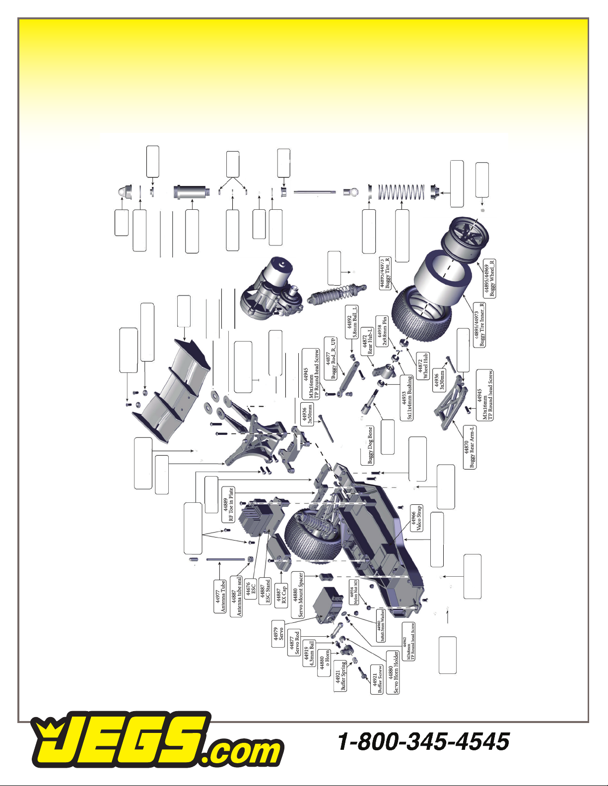
Main Chassis & Rear End Exploded View
2.6x6x0.5mm Washer
44943
M3X10mm
TP Round head Screw

Differential
Exploded View
Gearbox
Exploded View
10
® '
-
_,
-
-�
I
® '
-
_,
-
-�
I

Warranty
JEGS guarantees your new Stinger Buggy to be free from
defects and workmanship for a period 60 days from date
of purchase. The date of purchase must be veried by the
date on the sales receipt.
This warranty covers defects in material and workmanship
only. Problems that arise from normal wear, abuse,
neglect, or any damage that arises as a result of improper
use, incorrect batteries, overheating are not covered by this
warranty. The warranty also does not cover any problems
resulting from crashes.
JEGS is not liable for any loss or damages resulting from
the use or misuse of this product or any of the accessories
or chemicals related to the use of this product.
JEGS 2022 Version 01
Table of contents
Other Jegs Motorized Toy Car manuals


Popular Motorized Toy Car manuals by other brands


Lean Cars
Lean Cars CH9935 Installation and operating manual

Jamara
Jamara 405093 instruction manual

Rolly Toys
Rolly Toys Rolly Trac Lader manual

Eduard
Eduard ATF Dingo 2 GE A PatSi interior quick start guide

Agora Models
Agora Models STEVE MCQUEEN'S ICONIC PORSCHE 917KH Pack 10 Build instructions

HPI Racing
HPI Racing Brama 10b instruction manual