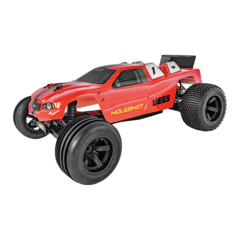
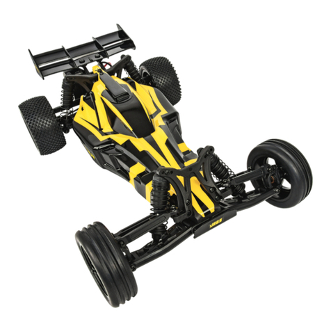
Jegs Torch User manual

Monster Truck Assembly Guide
555-44400 - Torch
555-44500 - Hooligan
Assembly Instruction & Parts List

Precautions
Precautions With Small Children
•
For children under the age of 13, parential guidance
is recommended when running.
Assembly Precautions
•
Choking hazard. Do not assemble near small children.
• Check the contents carefully before assembly. Please
contact Customer Service at: 1.800.345.4545 if you
have any defective or missing items.
•
Carefully read through this manual, and familiarize
yourself with the instructions.
•
Many different tools are required during assembly.
For safety purposes, please use the correct tools.
•
Exercise caution when using sharp tools such as a
hobby knife.
•
Many different materials are used in the construction of
these parts. Use extra care when handling parts with
sharp edges, such as machined metal components.
• When cutting plastic parts, watch for any ying parts.
•
Try to assemble any rotating parts or drivetrain parts
as carefully as possible.
•
Bundle wires neatly away from the ground or any moving
drivetrain components. Make sure that all wires are
securely connected to prevent electrical shorting.
Precautions Before Running
•
Some models may exceed speeds of 25 mph. Practice
common sense and run the car in open safe places, or
R/C car tracks.
•
Do not run the car on public roads with high
amounts of trafc, or in areas that may cause an
inconvenience to people in that area.
•
R/C cars are controlled using a radio frequency. In a
worst-case scenario radio interferences may cause
loss of control.
•
If others near you are running R/C cars, conrm that
they are not running on the same frequency.
•
This unit is manufactued with waterproof electronics,
but it should not be submerged in water for extended
periods of time.
• The drivetrain of an R/C car consists of many moving
parts like gears, shafts, and tires. Avoid touching these
areas when the battery is connected.
•
Many parts of an R/C car will become hot after
running. Allow the parts to sufciently cool before
conducting any maintenance.
Beginning a Run
1.
Place the R/C car so that the wheels are off the ground.
2.
Conrm that the speed controller switch is OFF, and
connect the motor and battery.
3. Switch the transmitter ON. (Do not use the transmitter
with low voltage. Ensure that the transmitter batteries
are good before use)
4. Turn the speed controller switch ON.
Ending a Run
1. Turn the speed controller switch OFF.
2. Disconnect the battery.
3. Turn the transmitter switch OFF.
Battery Usage
(Carefully read the instruction included with the batteries.)
•
When charging batteries, ensure nothing ammible
is in the surrounding area. Also avoid charging in
high-temperature locations.
•
When charging batteries, be sure to frequently monitor
the battery. Unattended, it could pose a re hazard.
• If the battery reaches 122º F or more, stop charging.
•
Batteries will become hot after running. Continuous
use of the battery pack may result in damage to
the cells. Allow the battery too cool down before
re-charging. Using a battery conditioner after running
may prolong the life and performance of the battery.
•
Please do not discard old battery packs in the trash.
Locate a battery disposal center.
Motor Usage
(Carefully read the instruction included with the motor.)
• Connecting a 7.2V battery directly to the motor can be
very dangerous.
•
Choose the appropriate gear ratio that matches the
motors power characteristics.
•
Using a gear ratio not suited to the characteristics of the
motor will not only prevent the motor from performing
at its optimum, but may damage the other electronics.
•
Motors will generally become very hot after running.
Continuous running will reduce the life of the motor.
Allow the motor to sufciently cool between each run.
1

Tools Required
Equipment Required
1.5 mm 2.0 mm 2.5 mm Socket
Wrench
Philips Screwdriver
(Not Included)
Battery
(Not Included)
Battery Charger
(Not Included)
Gear Grease
(Not Included)
Shock Oil [Silicone]
(Not Included)
Threadlock
(Not Included)
2

Shock Assembly
Bag A
555-44816
Shock Piston
555-44702
Shock Shaft
555-44858
O-Ring
555-44670
E-Clip
555-44816
Shock Shaft Guide
555-44806
3x6x0.5mm Washer
555-44816
Shock Body
555-44859
O-Ring (Black)
555-44816
Lower Ball End
Insert shaft guide and oil ring
into shock shaft as shown in
diagram. Make sure the shaft
guide is fully seated in the
shock body, refer to diagram.
555-44814
Shock Cap
555-44816
Upper Ball End
555-44813
Shock Diaphram
555-44816
Lower Shock Holder
555-44816
Shock Lower Rod End
555-44816
Spring Spacer
555-44816
Upper Spring Holder
555-44816
Shock Spring
3

555-44814
Shock Cap (Black)
555-44816
Upper Ball End
555-44806
3x6x0.5mm
Washer
555-44816
Shock Lower
Rod End
555-44813
Shock
Diaphram
555-44816
Shock Piston 555-44702
Shock Shaft
555-44858
O-Ring
555-44816
Spring Spacer
555-44816
Spring Holder
555-44816
Shaft Guide
555-44815
Shock Spring
55544859
O-Ring (Black)
555-44706
5.8mm Flanged
Pivot Ball
555-44816
Lower Spring
Holder
555-44816
Shock Body
555-44670
E-Clip
555-44706
5.8mm Flanged
Pivot Ball
555-44706
5.8mm Flanged Pivot Ball
Shock Assembly Continued
Bag A
Assembly x8
4

Front & Rear End Assemblies
Bag B
555-44726
Differential Case
555-44738
Planetary Gear
555-44857
10x12.5x0.1mm Shims
555-44738
Sun Gear
555-44817
Ring Gear M1x30T
555-44758
M2x8mm FH
555-4473210x15x-
4mm Bearing
555-44732
10x15x4mm Bearing
Assembly x2
555-44879
O-Ring (Black)
555-44856
5x7x0.2mm Shims
555-44734
5x10x4mm Bearing
555-44694
Differential Housing
555-44819
Drive Cup
555-447325x10x-
4mm Bearing
555-44818
Pinion Gear M1x13T
555-44758
M2x8mm FH
Assembly x2
Use Grease
Use Threadlocker
5

Front End Assembly
Bag B
555-44694
Differential Cover
555-44776
M3x18mm BH
555-44746
M2.5x18mm BH
555-44694
Solid Axle
555-44704
4-Link Bracket
B
A
555-44678
King Pin
555-44724
C Hub_B
555-44734
5x10x4mm Bearing
555-44760
M3x10mm BH
555-44690
Front Axle Shaft
555-44724
C Hub_A
555-44820
Wheel Axle
555-44678
King Pin
555-44822
Wheel Nut
555-44762
M3x10mm CH
555-44678
King Pin
555-44734
5x10x4mm Bearing
555-44724
C Hub_B
555-44724
C Hub_A
Front Front
Castor Angle Adjustment:
Recommended at the highest point, refer to the
diagram. Each point is a 15º increment increase.
About 3-3.5 mm
6

Front End Assemblies Continued
Bag B 555-44698
Lower Link (275WB)
555-44707
5.8mm Pivot Ball
555-44698
Upper Link (275WB)
555-44766
M3x14mm BH
About 10.3 mm
555-44800
M3x25mm Turnbuckle
555-44708
5.8mm Rod End
555-44706
5.8mm Flanged Pivot Ball
555-44708
5.8mm Rod End
555-44766
M3x14mm BH
555-44778
M3x30mm BH
555-44808
3x6x1mm Spacer
555-44810
3x6x2mm Spacer
555-44776
M3x18mm BH
555-44662
M3 Nylon Locknut
555-44662
M3 Nylon Locknut
555-44708
5.8mm Rod End
555-44708
5.8mm Rod End
555-44706
5.8mm Flanged Pivot Ball
555-44696
Steering Drag Link
7

Front End Assemblies Continued
Bag B
555-44706
5.8mm Flanged Pivot Ball
555-44706
5.8mm Flanged Pivot Ball
555-44708
5.8mm Rod End
555-44708
5.8mm Rod End
555-44804
M3x90mm
Turnbuckle
About 71.1mm
555-44766
M3x14mm BH
8

Rear End Assemblies
Bag B
A
B
B
A
555-44694
Differential Cover
555-44776
M3x18mm BH
555-44746
M2.5x18mm BH
555-44694
Solid Axle
555-44704
4-Link Bracket
Adjustable Anti Squat
15º Increments
555-44692
Rear Axle Shaft
555-44734
5x10x4mm Bearing
555-44854
2x10mm Pin
555-44833
Straight Axle Adapter
555-44760
M3x10mm BH
555-44822
Wheel Hex
9

Front & Rear End Assemblies
Bag B
Rear End Assembly
555-44766
M3x14mm BH
555-44698
Upper Link (275WB)
555-44707
5.8mm Pivot Ball
555-44698
Lower Link (275WB)
10

Center Differential Assembly
Bag C
Use Grease
Use Threadlocker
555-44736
5x8x2.5mm Bearing
555-44734
5x10x4mm Bearing
555-44825
2nd Gear
(Metal)
555-44722
Transmission Gear Box A
555-44722
Transmission Gear Box
Adjuster Cap
555-44794
M3x8mm Cap
555-44734
5x10x4mm Bearing
555-44855
2.8mm Pin
555-44825
Idle Gear
(Metal)
555-44700
2nd Gear Shaft
555-44821
Main Gear Shaft
555-44722
Transmission Gear Box B
555-44732
5x15x4mm Bearing
555-44758
M2x8mm FH
555-44825
Final Gear
(Metal)
555-44718
Center Locker
11

Center Differential Assembly Continued
Bag C
Recommended Slipper
Clutch Adjustment:
Tighten (clockwise) the
slipper nut until it stops
then back it off (counter
-clockwise) 3/4turn.
Use Grease
Use Threadlocker
555-44854
2x10mm Pin
555-44760
M3x8mm Cap
555-44830
Slipper Hub Set
555-44826
Slipper Pad
555-44794
M3x8mm Cap
555-44824
48P 85T Spur Gear
555-44852
M3x6mm Cap
555-44831
Slipper Spring
555-44740
M4 Nylon
Locknut
555-44710
5x10mm
Thrust Bearing
High Torque Ratio
(Standard)
High Speed Ratio
555-44837
Transmission Bracket
555-44760
M3x10mm BH
555-44776
M3x18mm BH
12

Use Threadlocker
Use Threadlocker
555-44840
ST Wiper B
555-44840
ST Wiper A
555-44840
ST Wiper C
555-44678
King Pin
Set the gear mesh
about 0.1mm gap
555-44680
RS 550 Motor
555-44827
48P 16T Motor
Pinion Gear
555-44843
Motor Heat
Sink Plate
555-44792
M3x8mm BH
Center Differential Assembly Continued
Bag C
555-44784
M23mm
Set Screw
555-44812
M3x7x0.25mm Washers
13

Center Differential Assembly Continued
Bag C
555-44792
M3x8mm BH
555-44790
M3x6mm FH
555-44720
Drive Cup (4.5mm)
555-44829
O-Ring (Black)
555-44838
Skid Plate
555-44720
Drive Cup (4.5mm)
555-44829
O-Ring (Black)
555-44722
Transmission
Gear Box Cover
14

Radio Tray
Bag D
555-44748
M2.5x6mm BH
555-44838
Receiver Cover
555-44750
M2.5x8mm BH
555-44838
Dust Cover
555-44684
Receiver
Double-Sided
Foam Tape
555-44838
Receiver Box
555-44792
M3x8mm BH
555-44792
M3x8mm BH
555-44792
M3x8mm BH
555-44792
M3x8mm BH
555-44716
Bumper Bracket
555-44760
M3x10mm BH
555-44792
M3x8mm BH
555-44836
Servo Tray
555-44688
275WB Chassis
Extension Plate
15

Radio Tray Continued
Bag D
Use Threadlocker
555-44676
40Amp ESC
Double- Sided
Foam Tape
555-44792
M3x8mm BH
555-44844
Servo
555-44812
3x7x0.25mm Washers
555-44764
M3x12mm BH
555-44841
Servo Saver Cap
About 48.5mm
555-44802
M3x25mm Turnbuckle
555-44706
5.8mm Flanged Pivot Ball
555-44708
5.8mm Rod End
555-44708
5.8mm Rod End
555-44706
5.8mm Flanged Pivot Ball
555-44770
M3x12mm BH
555-44841
Servo Saver Cap
555-44853
Servo Saver Spring
555-44841
Servo Arm
555-44662
M3 Nylon Locknut
16

Radio Tray Continued
Bag D
555-44852
Set Screw Shaft
555-44714
Body Post
Radio Tray Assembly
17

555-44712
Battery Tray
555-44678
King Pin
555-44836
Rear Bumper Stay
555-44792
M3x8mm BH
555-44792
M3x8mm BH
555-44792
M3x8mm BH
555-44760
M3x10mm BH
555-44716
Bumper Bracket
555-44852
Set Screw Shaft
555-44714
Body Post
Battery Tray
Bag E
18

Chassis
Bag G
555-44674
Center Drive Shaft
555-44674
Center Drive Shaft
555-44766
M3x14mm BH
19
This manual suits for next models
3
Table of contents
Other Jegs Motorized Toy Car manuals
Popular Motorized Toy Car manuals by other brands

HPI Racing
HPI Racing Firestorm 10T instruction manual

LEGO
LEGO Racers Supersonic RC 8366 Building instructions

Jazwares
Jazwares Fortnite The Baller instruction manual
DeAGNOSTINI MODEL SPACE
DeAGNOSTINI MODEL SPACE Red Bull Racing RB7 Build manual

AK
AK FJ43 PICKUP with SPG-9 recoilless gun Assembly instructions

Arrma
Arrma 4x4 3S BLX quick start guide
Carrera RC
Carrera RC RC POWER FIRST Carrera RC Racer Assembly and operating instructions
SWorkz
SWorkz S35-GT instruction manual
KID Trax
KID Trax KT1309TR manual

RED CAT
RED CAT Tremor SG instruction manual
Spinmaster
Spinmaster DC BATMOBILE RC quick start guide
KID Trax
KID Trax SRT Viper KT1124WM owner's manual
