JEICO JREMO 6K+ User manual

O&M MANUAL
JREMO 6K+
REMOTE CONTROL
www.jeico.com

JREMO 6K+
Industrial radio remote controller
JREMO® INDUSTRIAL REMOTE CONTROLLER
MODEL
Serial No.
Channel
No.
Lot No.
JREMO® Remote Controllers must be handled, installed,
operated, and maintained by (an) authorized
and (a) qualied person(s), and
Upon the above condition guaranty period from the date of
(delivery, installation, inspection)
shall be one calendar year.
Subject to conrming defects not caused by improper installation,
improper operation and/or insucient
maintenance, unauthorized modication, ignorance of
environmental specications, or improper interfacing,
irresistible forces such as war(s), strike(s), Act(s) of God, and so on;
all such the defects shall be treated as in no warranty.
WARRANTY

03
JREMO 6K+
Industrial radio remote controller
Contents
PRECAUTIONS ………………………………………………… 04
CHAPTER I. GENERAL SPECIFICATIONS …………… 06
1.1. COMMON SPECIFICATION ……………………………… 06
1.2 Transmitter (Tx) …………………………………………… 06
1.3 RECEIVER (Rx) ……………………………………………… 06
1.4 Model Suxing …………………………………………… 06
CHAPTER 2. JREMO 6K+ Standard Set …………… 07
2-1 Standard set ……………………………………………… 07
2-2 CONTROL CONTACTS WIRE DIAGRAMS ……………… 08
CHAPTER 3. INSTALLATION & FUNCTION SETTING ………
09
3-1 CAUTIONS FOR INSTALLATION
………………………………
09
3-2 HOW TO INSTALL TRANSMITTER (TX)
……………………
10
3-3 HOW TO INSTALL RECEIVER (RX)
……………………………
11
3-4 HOW TO START
……………………………………………………
12
CHAPTER 4. MAINTENANCE
……………………………………
13
4-1 Standard Operation
………………………………………………
13
4-2 FUSES
…………………………………………………………………
13
CHAPTER 5. TROUBLESHOOTING
…………………………
14
5-1 SELF DIAGNOSIS (LED SIGNAL ERROR MESSAGE)
……
14
5-2 LED Diagnosis
………………………………………………………
14
5-3 Troubleshooting
……………………………………………………
15
APPENDIX Ⅰ - 433 BAND FREQUENCY TABLE
…………………
16
APPENDIX Ⅱ - 447 & 173 & 429 FREQUENCY TABLE
…………
17
APPENDIX III - OPTIONAL ACCESSORIES
…………………………
18

04
JREMO 6K+
Industrial radio remote controller JREMO 6K+
Industrial radio remote controller
A. ANNOUNCEMENT
▪ This O&M Manual is for JREMO 6K+ and the specication in each model is
referred to Chapter 1.
▪ Before installation and operation look through this manual and make sure
having a full acknowledgement of this manual.
▪ JREMO series remote controllers compose a High-Tech systemized, and a
full knowledge of this manual is a must in advance of installation as well as
operation of this remote controllers.
▪ Do not try to dismantle or unscrew JREMO series except a skilful, an expert,
and an authorized.
▪ This manual is for reference and good for installation and for maintenance.
For more details consult an adjacent agent and/or supplier.
▪ Each and all the JREMO series remote controller is tested under severe
condition and passed without any default found at factory and is ready for
an immediate use for a normal/insucient condition or so, however, in an
emergency and/or in an any dangerous possibility, do not use.
▪ After use switch o the main power of the equipment(ex. crane) and conrm
the receiver power o, and then turn o the rotary key of the transmitter
before pull out the key, and store the key in an isolated area.
▪ When not in use stay the transmitter in a safety area and do not allow an
unauthorized to
attempt to use it.
▪ Equipment (ex. crane) using this remote controller must have main relays,
limit switches, separate COM lines, and other appropriate devices for safety
operation. ▪When metal container for receiver casing is used make sure
Ground(GND) to be sure connected to metal part of equipment (ex. crane).
▪Do not use in a severe interfered area and/or lightening or so. • Make sure
power sources are correct. ▪Power o and do not use during installation
and/or maintenance so as to avoid any electric shock or so. ▪Do not try to
copy, modify, or release this remote controllers without permission in ad-
vance by JEICO, such an action is illegal. JREMO series remote controller
have many international patents, certicates, and so on.
▪ Without notice in advance and within JEICO’s discretion this manual may be
revised, added, and/or deleted for better use.
PRECAUTIONS

05
JREMO 6K+
Industrial radio remote controller
B. GENERAL CAUTIONS
▪ Operator must be healthy both physically and mentally.
▪ Even though this remote controller is versatile, durable, and good for out-
door use try to avoid an excessive shock, pressure, wind, snow, rain, ices, or
sunlight, high temperature, humid, gas, and etc.
▪ JREMO 6K+ is the insertion of battery exchange.
▪ During operation of 6K+ when found power is weak replace all the batteries
with all new 2 AA batteries. ▪When not in use take out batteries from the
transmitter and put aside in a dierent area.
▪In an emergency follow up the below emergency measures.
C. EMERGENCY MEASURES
JREMO® Series has designed for safety, meeting with various kind of emer-
gencies and for self-recovering. Billions of dierent I.D. code, Self-Diagnoses,
super qualied and isolated protection against voltage surges and/or inter-
feres, etc. are the basic integral functions for solving any unexpected accident
or trouble in an emergency. So when such an emergent function is detected,
JREMO® Series will o the work immediately and stop all the function auto-
matically.
For emergency follow up the below procedure in advance and then call an
adjacent JEICO® agent and/or supplier for an emergency service.
1. Press EMS(Emergency Stop) Button. (red mushroom at top)
2. Power o receiver power. Power o main power of Equipment.
3. Inquire adjacent JEICO® agent and or supplier.
PRECAUTIONS

06
JREMO 6K+
Industrial radio remote controller JREMO 6K+
Industrial radio remote controller
Chapter 1. GENERAL SPECIFICATIONS
1.1. COMMON SPECIFICATION
- Frequency Ranges & Channel Numbers
433 Bands : 433.050~434.7750 Mhz, 70 channels
447 Bands : 447.600~447.9875 Mhz, 32 channels
173 Bands : 173.025~173.7875 Mhz, 35 channels
429 Bands : 429.2500~429.7375Mhz, 40 channels
- I.D. Code : 232 (Over 4 Billion)
- Temperature : -10 ℃ ~ +60 ℃
- Remote Distance : 30 ~ 150 M.
- Case Construction : Glass-Fiber
- Protection Grade : (Tx) IP55 / (Rx) IP66
1.2 Transmitter (Tx)
- Power : 6K+ ⇨ 2 x 1.5 V Alkaline Batteries (LR6 AA Size)
- Type : Single or Double Push Button Type
- Size : 148 x 48 x 45 mm (L x W x H)
- Output : ≤ 5mW
- Wgt : Approx. 185 gr. (Batteries Incl)
1.3 Receiver (Rx)
- Casing : RX3
- Power : AC110~440V or DC12~40V(OPT AC48V, DC 60V)
- Type : Remote ON Main Lamp Indication
- Ralay : AC =>“A” Contact, 250VAC/5A, 125VAC/10A
DC =>“A” Contact, 24VDC/15A, 120VAC/15A
- Size, mm : 90 x 152 x 105
- Weight, gr. : 950(Antenna & Power/Relay Cable Incl.)
1.4 Model Suxing
Chapter 1.
GENERAL SPECIFICATIONS
JREMO 6K+ A (RX3)
Model Name
Sux
(Receiver Type, Normally not written)
6K+
AStandard,
7 Single
RX3
B6 Double + 1 Single
CUp/Down Double
MDC , 7 Single P/B
Model
Type

07
JREMO 6K+
Industrial radio remote controller
CHAPTER 2. JREMO 6K+ Standard Set
2-1 STANDARD SET
CHAPTER 2. JREMO 6K+ Standard Set
JREMO 6K+ Standard Set comprises one transmitter and one receiver as following as a set.
Single or
Double P/B
Single P/B
Single P/B
173 x 62 x 46 mm
Approx. 355 gr.
RX3
90 x 215 x 105 mm
Approx. 1,350 gr.
Tx Rx
■ FUNCTIONS MODEL NAME RECEIVER SIZE
Standard Single P/B : JREMO 6K+ A ⇨ RX3 (22 Core Cable)
U/D Creep(Double) P/B : JREMO 6K+ B ⇨ RX3 (22 Core Cable)
6 Double P/B : JREMO 6K+ C ⇨ RX3 (22 Core Cable)
■ Tx Button Labelling can be in English, Chinese, Japanese, Spanish, or
other languages upon request.

08
JREMO 6K+
Industrial radio remote controller JREMO 6K+
Industrial radio remote controller
2-2 CONTROL CONTACT WIRE DIAGRAM
▪RECEIVER : RX3
SIZE : 90 x 215 x 105 mm, approx. 1,350 gr.
▪CABLE SPEC. : 0.75 Sq, 600VAC, 22 Core,
approx. 1.7 m long, numbered
▪RELAY SPEC. : 250VAC/5A, 125VAC/10A
“A” Contact
▪INPUT POWER : AC 110 ~440V 50/60Hz
▪FUSE SPEC. : 1A(F1) / 10A(F2), 20MM Column Fuse
▪INPUT POWER : AC 110 ~440V 60/60Hz, DC 12 40V (opt. 60V)
CHAPTER2. JREMO 6K+ Standard Set
EMS Stop Button
(Mushroom)
Main On Lamp

09
JREMO 6K+
Industrial radio remote controller
CHAPTER 3. INSTALLATION & FUNCTION SETTING
3-1 CAUTIONS FOR INSTALLATION
1. Follow up all the safety rule of equipment (ex. crane)
2. Switch o the main power of equipment (ex. crane) in a rst action.
3. Install receiver where there will have any other obstructions.
4. Fix receiver rmly.
5. Use an optional external antenna in case receiver installs inside the met-
al closed box or electrical panel.
6. Check safety devices of equipment(ex. crane) before installation and
conrm it is under utmost safety condition.
7. Do not try to install without gaining in skill for electrical circuit diagrams
and operation circuits of equipment(ex. crane), remote controller's func-
tions, etc for avoiding an unexpected accident, wrong functions, etc.
8. For avoiding any possible interferes install receiver far from motor and
transducer as following illustration :
9. Install receiver top outside of electrical control box and installation in
inside the control box is not a proper method.
CHAPTER 3. INSTALLATION & FUNCTION SETTING
RECEIVER
MOTOR TRANS
CABLE
Min. 3M DISTANCE
⇨
RECEIVER
E L E C T R I C A L
CONTROL BOX
E L E C T R I C A L
CONTROL BOX
ANTENNA RECEIVER

10
JREMO 6K+
Industrial radio remote controller JREMO 6K+
Industrial radio remote controller
CHAPTER 3. INSTALLATION & FUNCTION SETTING
3-2 HOW TO INSTALL JREMO® SERIES TX
3-2-1. BATTERIES
A. Insert 2 AA batteries at right position with + and -. An opposite position
will cause an excessive heat to cause battery leakage, burning, and so
on, any malfunction caused by such the poor batteries' handling will not
be of free recovery no matter how long the guarantee period remained.
B. Precautions
1. Do not use low power type rechargeable batteries.
Recommend : Use 2500mAH or above.
2. Use all new & fully charged batteries for replacement.
Any un-fully charged one(s) may cause the same to the above clause
3-2-1 A matters.
C. Change of Batteries : When led signals with red and green ashes in turn
it shows battery powers are low. Replace them all 2 batteries immediate-
ly and simultaneously with new ones.
D. When not in use press down the EMS button for saving battery life as
well as o the battery power, and for safety as well.
3-2-2. FUNCTION SETTING & COPYING
In case to change either Tx or Rx, or modify functions its mating transmitter
and receiver must be identical and set both at the same time for sure
identication. Function settings can be done either by the copier or by PC
software, or from direct Rx-Rf at Rx to/from Tx. Either method is an optional.
A. Function set by Copier
1. Unscrew Battery Cap at Tx and Open the top
cover at Rx.(Please note when the Copier to
use both Tx and Rx power should be shut
down.)
2. Connect Copier either to Tx or Rx.
3. Follow the instruction of Copier Manual
that will be provided as an optional order.
B. Function set by Software
1. Software can be provided as an optional order
and,
2. It needs another connector (i.e. Gender) with
Copier
Gender

11
JREMO 6K+
Industrial radio remote controller
CHAPTER 3. INSTALLATION & FUNCTION SETTING
the software.
C. Direct Copying from Rx
1. Connect Tx and Rx by a connector cable (an optional provision).
2. Place the COPY-RUN s/w nob to COPY position, and Tx Led will blink
with green light.
3. Paring (Copying) from Rx to Tx done.
4. Unplug the connector and place the s/w to RUN position.
D. Consult JEICO distributor and/or agent for further support.
3-3 HOW TO INSTALL JREMO® SERIES RX
3-3-1. PREPARATIONS
A. Prepare tools.
B. Select a proper place for installation.
1. Choose a safe area, a visible area of receiver or antenna.
2. Avoid a spark area (ex. motors, relays, magnet switches, electric cables
are likely generating sparks and interferes)
3. Avoid high voltage and current area.
4. Receiver is to be distanced at least 3cm from obstacles.
C. Match receiver power
1. Check input power source and make sure to connect to the right position.
2. In case DC power, make sure receiver is also for DC.
3. AC Power
Use AC Receiver.
Standard AC power source is 110 ~ 440V Free Volts.
24V, 48V etc. are optional.
4. DC Power
Use DC Receiver.
Standard DC power source is DC12 ~ 40V Free Volts.
For 48VDC, 60VDC consult JEICO distributor and/or agent.

12
JREMO 6K+
Industrial radio remote controller JREMO 6K+
Industrial radio remote controller
CHAPTER 3. INSTALLATION & FUNCTION SETTING
3-3-2. INSTALLATION SEQUENCE
A. Power o equipment(ex. crane).
B. Use with the Fixing Plate provided together with Rx for sure installation
for absorbing and preventing vibration, shock, etc possibly causing upon
operation.
C. If available install RX to the position where the cable gland faces to the
downward direction, and do not put it to the upward way.
D. Connect only main power (wire no. 1 & 2) and main relay (EMS) ON (wire
no. 3 & 4) wires to the mating terminal of equipment.
E. At Tx twist up the red EMS button and push any button town and nd if
the Rx Lamp is ON.
F. If it is necessary for conrming functions of each output relay of RX then
open the upper case of RX and nd if they are correct functioning both
by hearing clicking sound and/or by looking led signaling at each related
relay(s). When all are o.k. then
G. O the Rx power and push down red EMS button of Tx.
H. After o the power of Rx & Tx, connect all the remained functional each
wire of Rx to a mating terminal of equipment(ex. crane).
1. Conrm both circuit diagram of receiver and equipment(ex. crane)
are in sequence and connected correctly.
2. Conrm ground is O. K.
3. Check and conrm again power source.
F. Switch on receiver power by setting to remote at the selector switch
(manual/remote) if selector s/w is installed. If selector switch is not used
and connected the power line directly to the main, then the receiver
power is automatically on upon connected.
G. Check functions by using of Tx (Transmitter) as following :
1. Twisting up the EMS button and do as START ON Function.
2. And, conrm if the Tx (Receiver) MAIN Lamp is on.
H. Press each function button of transmitter and conrm all the related
functions are in normal.
3-4 HOW TO START
For the safety and secure operation JREMO series has adopted several
types of start functions as following to achieve enhanced safety :
■ Main ON Function
Standard Preset : EMS UP ⇨ Any button, Main ON
Optional Preset : EMS UP ⇨ Start P/B, Main ON
13
JREMO 6K+
Industrial radio remote controller
CHAPTER 4. MAINTENANCE
4-1 STANDARD OPERATION
A. Twist up the EMS button of Tx and do as START ON function procedure
preset and nd the Rx Main Lamp ON. During normal operation see if the
Tx led shows Green light which is normal, and if the battery power of Tx
goes weak then the Tx led light will turn to red and green by turns, and it
still runs normally for some time. When it comes stop the operation be-
fore any abnormal functions such as delay responses, intermitting runs,
no stops, etc during working with both red and green light signalling.
B. Press down the EMS button when every normal operation nished and/
or in any emergency situation might occur do the same at once.
C. In case not in use for a long-term operation, take o all the batteries
from tx for avoiding of any contamination and/or unnecessary consump-
tion of battery power.
CHAPTER 4. MAINTENANCE
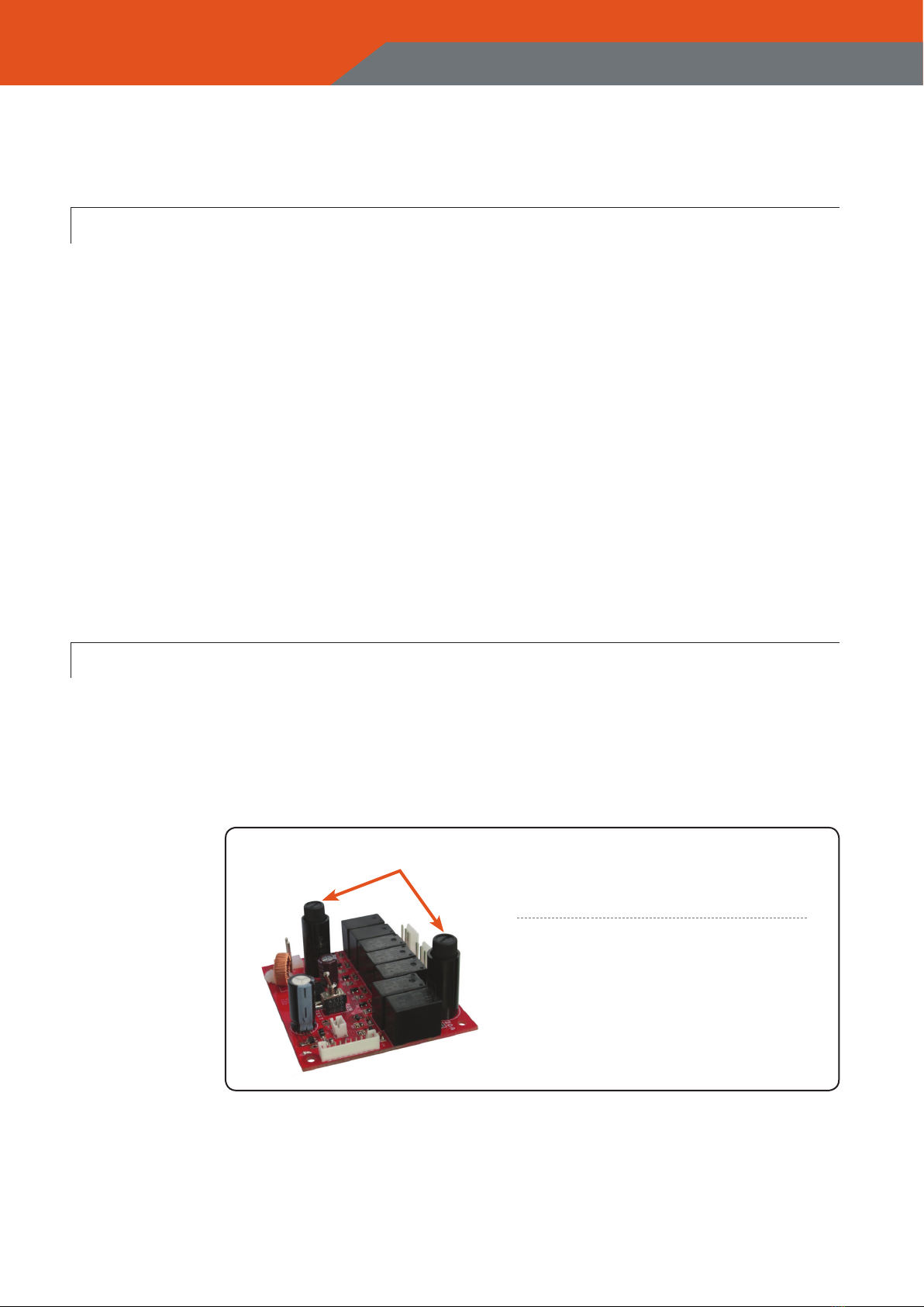
4-2 FUSES
A. A replaceable fuse is put inside the fuse column.
B. For replacement of fuse, use a athead screwdriver or by hand to push
down head of the fuse cap by rotating 90°anticlockwise to open the cap.
C. Replace with a new fuse and close the cap in opposite procedure.
Fuse Cap
FUSE CAPACITY
AC Board DC Board
POWER(F1) : 1A 5A
MAIN (F2) : 10A 20A
14
JREMO 6K+
Industrial radio remote controller JREMO 6K+
Industrial radio remote controller
CHAPTER 5. TROUBLESHOOTING
5-1 SELF DIAGNOSIS (LED SIGNAL ERROR MESSAGE)
JEICO remote controllers have a renewed method of self diagnostic trou-
bleshooting against so much complicated and riddled electronic struc-
tures, and yet it is easy to check and nd causes and measures for any
malfunctions may occur. JEICO takes a type of Led signaling error message
for better, quick restoration in normal even at site.
CHAPTER 5. TROUBLESHOOTING
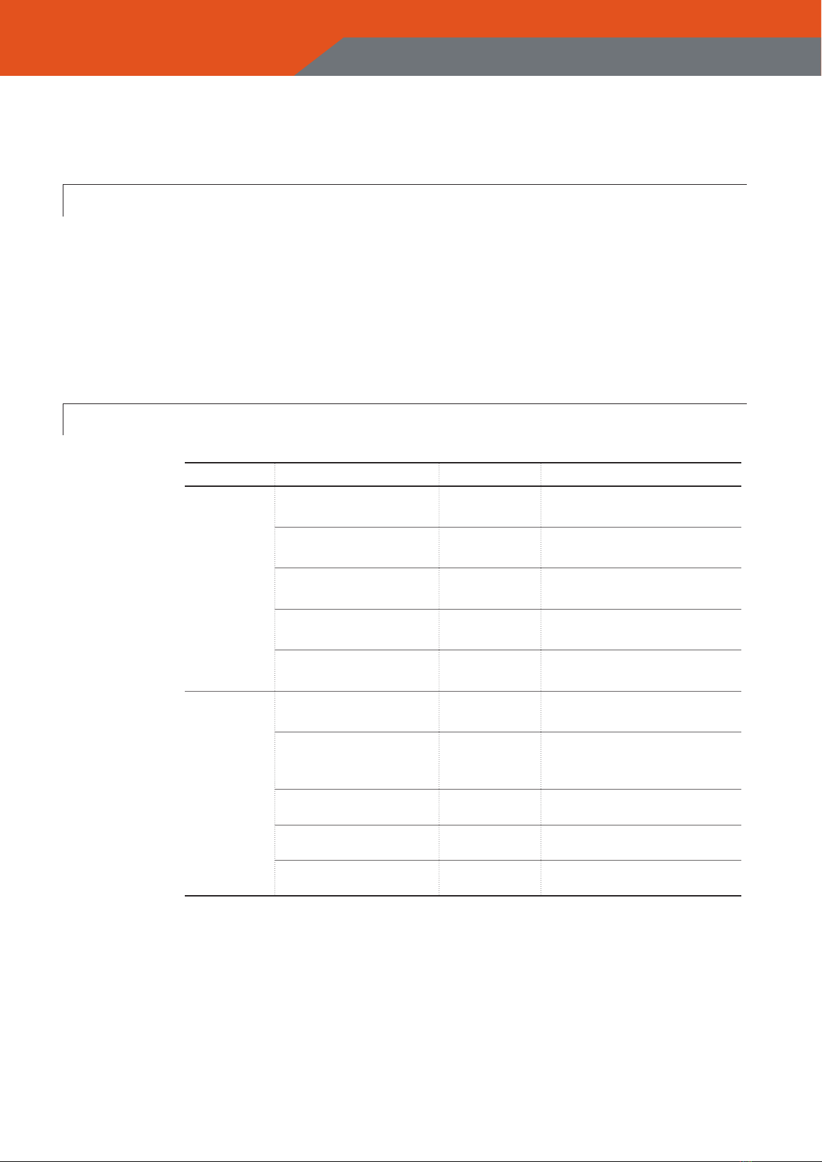
5-2 LED Diagnosis
Causes LED Signals Measures
Transmitter
(TX)
EMS Button not up Red Light Pull up EMS Button
Push Button defect Red Flash Replace with new button(s)
Encoder Module defect No Signal Replace with a new module
Batteries Consumed No Signal Replace with new batteries
Low Power Red & Green
Flashes Replace with new batteries
Receiver
(RX)
Decoder defect Lamp O Replace with a new Rx/Rf
Wrong Power Source Lamp O Replace Fuses and/or
Replace Relay Board
Connect Right Power
Main Relay defect Lamp O Replace Main Relay
Rx-Rf COPY position Lamp O Set to RUN position
Main Power O Lamp O Engage Main Power

15
JREMO 6K+
Industrial radio remote controller
CHAPTER 5. TROUBLESHOOTING
5-3 Troubleshooting
Appearances Causes Measures
Tx Led
No Signal &
Not Working
1. Wrong Bat. Direction
2. Battery Consumed
3. Old Batteries
4. Encoder Module defect
1. Place in right pole direction
2. Replace with new batteries
3. Replace with new batteries
4. Replace with new module
Tx Led
Red Light &
Not Working
1. EMS Button Not Up
2. Very Low Batteries
3. Old Batteries
4. Button Jam
1. Twist Up EMS Button
2. Replace with new batteries
3. Replace with new batteries
4. Replace with new buttons
Tx Led
Red and Green
Flashes & Working
1. Low Battery Power
2. Old Batteries
1.Replace with new batteries
2. Replace with new batteries
Tx Led
Green Flashes
& Not Working
1. Tx Antenna defect
2. Rx/Rf Module defect
3. Rx Antenna defect
4. Wrong Rx Power
5. Cable Short-circuit
6. No Remote Positioned
7. Frequency Interferes
1. Replace with new antenna
2. Replace with new Rx/Rf
3. Replace with new antenna
4. Correct Rx power source
5. Change with new Cable
6. Set to Remote Position
7. Set to other channel
Rx Lamp ON &
Not Working
1. Cable Short-circuit
2. No Remote Positioned
3. Frequency Interferes
4. Relay defect
6. Out of distance
1. Change with new Cable
2. Set to Remote Position
3. Set to other channel
4. Replace relay with new one
6. Be in a running area
Rx Lamp OFF &
Not Working
1. Tx Antenna defect
2. Rx Antenna defect
3. Rx/Rf Module defect
4. Power Short-circuit
5. Frequency Interferes
6. Main Fuse Burned
7. Main Relay defect
8. Rx-Rx COPY position
1. Replace with new antenna
2. Replace with new antenna
3. Replace with new Rx/Rf
4. Change with new Cable
5. Set to other channel
6. Replace fuse with new one
7. Replace relay with new one
8. Set to RUN position

16
JREMO 6K+
Industrial radio remote controller JREMO 6K+
Industrial radio remote controller
APPENDIX I : 433 BAND FREQUENCY TABLE
APPENDIX I : 433 BAND FREQUENCY TABLE
CH. NO. MHz
001 433.050
002 433.075
003 433.100
004 433.125
005 433.150
006 433.175
007 433.200
008 433.225
009 433.250
010 433.275
011 433.300
012 433.325
013 433.350
014 433.375
015 433.400
016 433.425
017 433.450
018 433.475
019 433.500
020 433.525
021 433.550
022 433.575
023 433.600
024 433.625
025 433.650
026 433.675
027 433.700
028 433.725
029 433.750
030 433.775
031 433.800
032 433.825
033 433.850
034 433.875
035 433.900
TOTAL NUMBERS : 70 CHANNELS
Channel Spacing : 25 Kc
CH. NO. MHz
036 433.925
037 433.950
038 433.975
039 434.000
040 434.025
041 434.050
042 434.075
043 434.100
044 434.125
045 434.150
046 434.175
047 434.200
048 434.225
049 434.250
050 434.275
051 434.300
052 434.325
053 434.350
054 434.375
055 434.400
056 434.425
057 434.450
058 434.475
059 434.500
060 434.525
061 434.550
062 434.575
063 434.600
064 434.625
065 434.650
066 434.675
067 434.700
068 434.725
069 434.750
070 434.775
Calculation : Mhz = 433.050 + (N-1) x 0.025, 01≤N≤70

17
JREMO 6K+
Industrial radio remote controller
APPENDIX II : 447 & 173& 429 FREQUENCY TABLE
APPENDIX II : 447 & 173 & 429 FREQUENCY TABLE
CH. NO. MHz
001 447.6000
002 447.6125
003 447.6250
004 447.6375
005 447.6500
006 447.6625
007 447.6750
008 447.6875
009 447.7800
010 447.7125
011 447.7250
012 447.7375
013 447.7500
014 447.7625
015 447.7750
016 447.7875
017 447.8000
018 447.8125
019 447.8250
020 447.8375
021 447.8500
022 447.8625
023 447.8750
024 447.8875
025 447.9000
026 447.9125
027 447.9250
028 447.9375
029 447.9500
030 447.9625
031 447.9750
032 447.9875
033 -
034 -
035 -
TOTATAL NUMBERS : 32 (447 Bands) / 35 (173 Bands) / 40 (429 Bands) CHANNELS
Channel Spacing : 12.5Kc
CH. NO. MHz
001 173.0250
002 173.0375
003 173.0500
004 173.0625
005 173.0750
006 173.0875
007 173.1000
008 173.1125
009 173.1250
010 173.1375
011 173.1500
012 173.1625
013 173.1750
014 173.1875
015 173.2000
016 173.2125
017 173.2250
018 173.2375
019 173.2500
020 173.2625
021 173.2750
022 173.6250
023 173.6375
024 173.6500
025 173.5625
026 173.6750
027 173.6875
028 173.7000
029 173.7125
030 173.250
031 173.7375
032 173.7500
033 173.7625
034 173.7750
035 173.7875
Calculation : Mhz = 447.6000 + (N-1) x 0.125, 01≤N≤32
Calculation : Mhz = 173.0250 + (N-1) x 0.125, 01≤N≤35
Calculation : Mhz = 429.2500 + (N-1) x 0.125, 22≤N≤40
CH. NO. MHz
001 429.2500
002 429.2625
003 429.2750
004 429.2875
005 429.3000
006 429.3125
007 429.3250
008 429.3375
009 429.3500
010 429.3625
011 429.3750
012 429.3875
013 429.4000
014 429.4125
015 429.4250
016 429.4375
017 429.4500
018 429.4625
019 429.4750
020 429.4875
021 429.5000
022 429.5125
023 429.5250
024 429.5375
025 429.5500
026 429.5625
027 429.5750
028 429.5875
029 429.6000
030 429.6125
031 429.6250
032 429.6375
033 429.6500
034 429.6625
035 429.6750
036 429.6875
037 429.7000
038 429.7125
039 429.7250
040 429.7375

18
JREMO 6K+
Industrial radio remote controller
APPENDIX Ⅲ : OPTIONAL ACCESSORIES
APPENDIX Ⅲ : OPTIONAL ACCESSORIES
RAIN/DUST COVER
MAGNET ANTENNA Rx Fixing Plate Rx Fixing Bracket
or
Copier PC Gender & Software
Tx Hook
Full Cover
(Water & Oil free)
Silicon &
Leather Cover

J Building, 94-1, Choryang-ro, Dong-gu, Busan, 48805, Korea
www.jeico.com
www.jeico.com
Table of contents
Other JEICO Remote Control manuals


