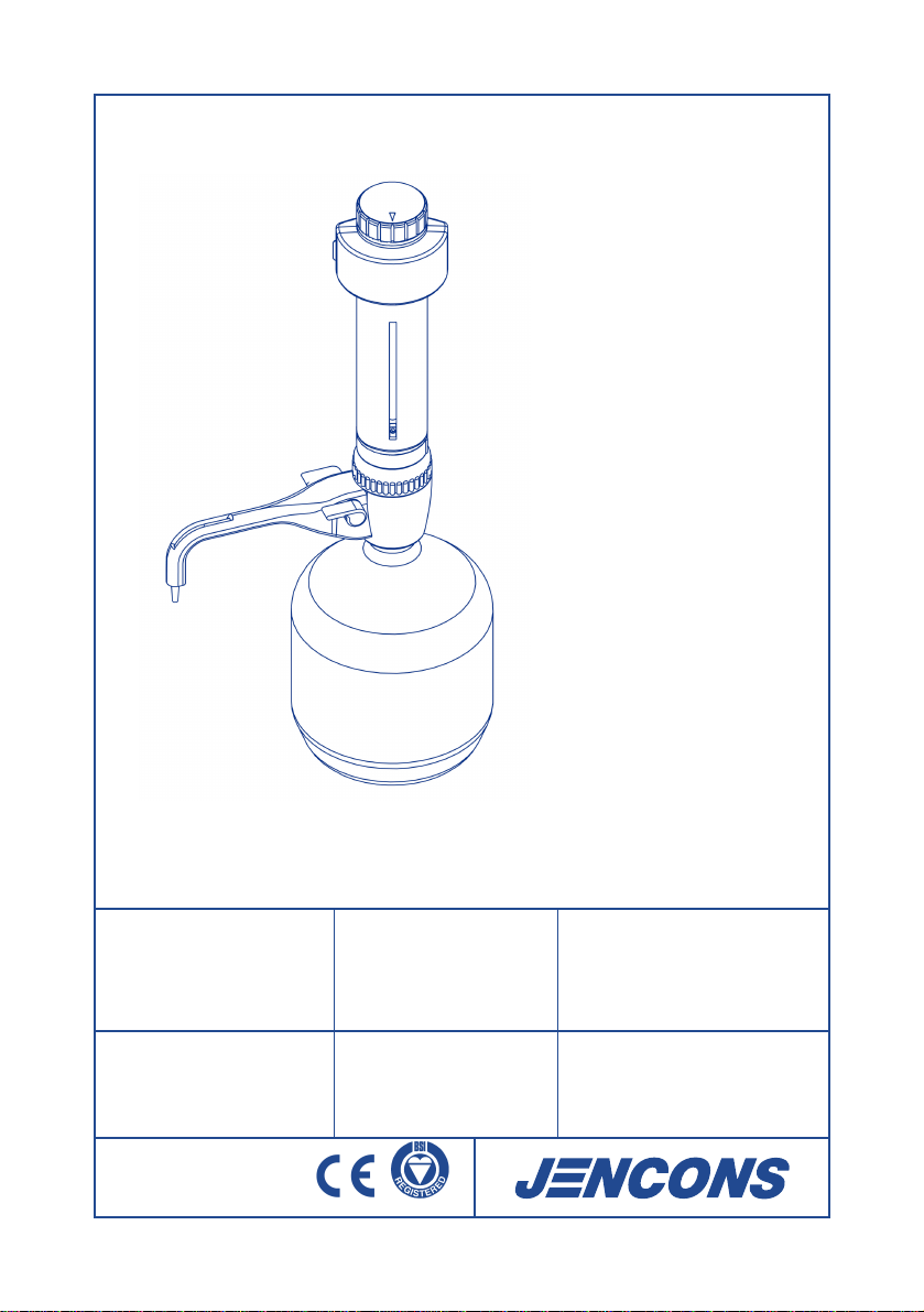
JENCONS ZIPPETTE PRO Series Specifications
Operator Instructions
2 – 12
Notice D´Emploi
13 – 23
Gebrauchsanweisung
24 – 34
Manual Del Operador
35 – 45
Notes
46 – 47
Jencons Scientific Inc (USA)
800 Bursca Drive, Suite 801
Bridgeville, PA 15017
Phone: 412 257-8861
Toll Free: 800 846-9959
Fax: 412 257-8809
Email: [email protected]
Website: www.jenconsusa.com
Jencons Scientific Ltd
Cherrycourt Way Ind. Est.
Stanbridge Rd, Leighton Buzzard
LU7 4UA, ENGLAND
Phone: 01525 372010
Fax: 01525 379547
Int. Phone: +44 1525 372010
Int. Fax: +44 1525 851461
Email: [email protected]
Website: www.jencons.co.uk
Online sales: www.ecomcat.co.uk
ISO 9001:2000
FM 15114

Operator
Instructions
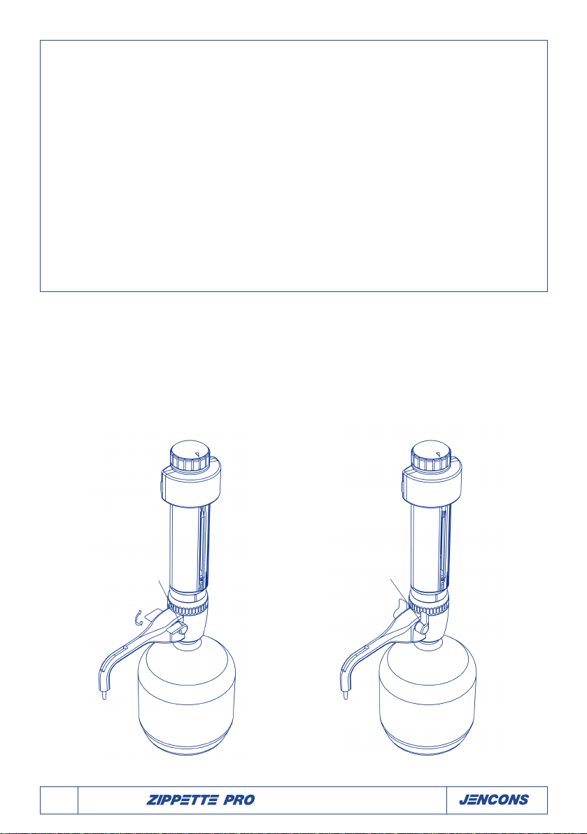
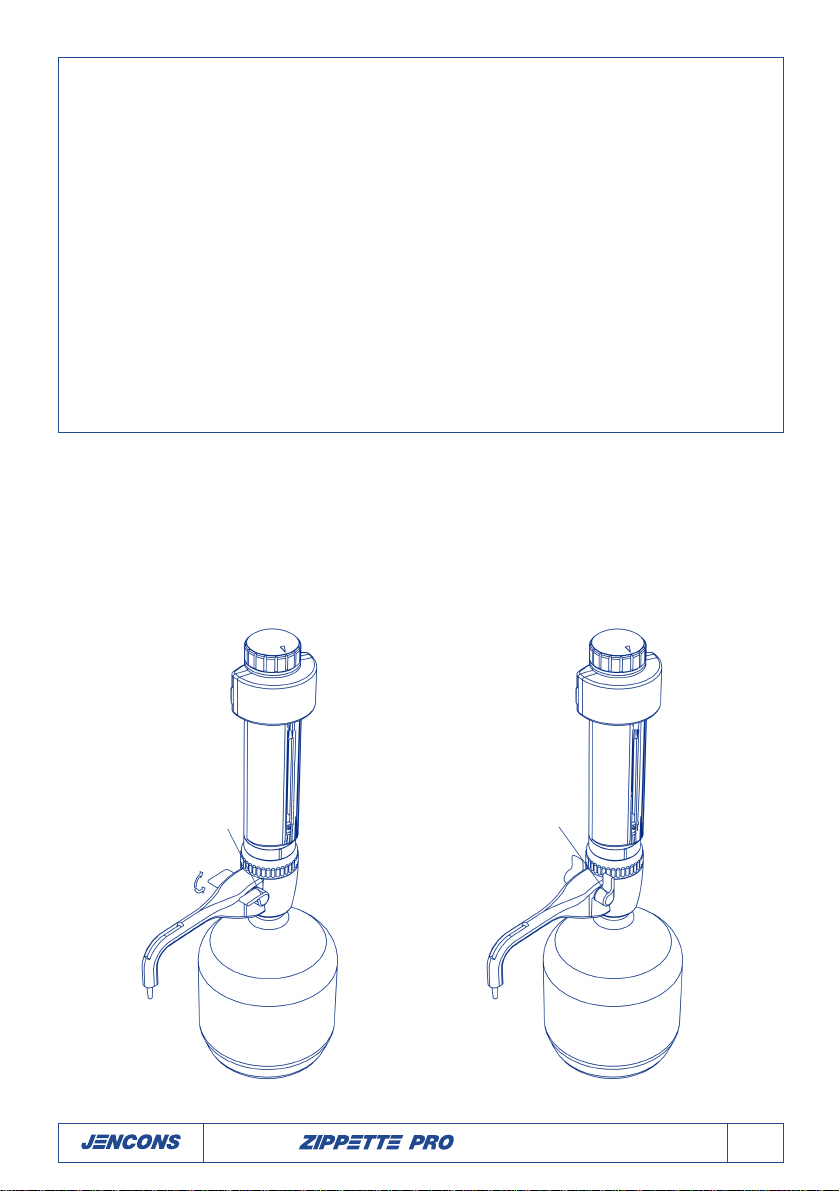
Zippette Pro 0-30ml manual priming
Zippette Pro 0-30ml spring-loaded
2Operator Instructions
Contents
General Safety Instruction . . . . . . . . . . . . . . . . . . . . . . . . . . . . . . . . . . . . . . . . . . . . . . . . . . . . . . . .This page
Restriction of Use . . . . . . . . . . . . . . . . . . . . . . . . . . . . . . . . . . . . . . . . . . . . . . . . . . . . . . . . . . . . . . . . . . . .3
Before Using the Zippette . . . . . . . . . . . . . . . . . . . . . . . . . . . . . . . . . . . . . . . . . . . . . . . . . . . . . . . . . . . . . .3
Assembly . . . . . . . . . . . . . . . . . . . . . . . . . . . . . . . . . . . . . . . . . . . . . . . . . . . . . . . . . . . . . . . . . . . . . . . . . .3
Operating Instructions . . . . . . . . . . . . . . . . . . . . . . . . . . . . . . . . . . . . . . . . . . . . . . . . . . . . . . . . . . . . . . . . .3
Inserting the return spring . . . . . . . . . . . . . . . . . . . . . . . . . . . . . . . . . . . . . . . . . . . . . . . . . . . . . . . . . . . . . .4
The volume adjustment knob . . . . . . . . . . . . . . . . . . . . . . . . . . . . . . . . . . . . . . . . . . . . . . . . . . . . . . . . . . . .6
User Calibration procedure . . . . . . . . . . . . . . . . . . . . . . . . . . . . . . . . . . . . . . . . . . . . . . . . . . . . . . . . . . . . .6
Maintenance/Cleaning . . . . . . . . . . . . . . . . . . . . . . . . . . . . . . . . . . . . . . . . . . . . . . . . . . . . . . . . . . . . . . . . .6
Sterilisation/Autoclaving . . . . . . . . . . . . . . . . . . . . . . . . . . . . . . . . . . . . . . . . . . . . . . . . . . . . . . . . . . . . . . . .7
Fluid-Path disassembly procedure . . . . . . . . . . . . . . . . . . . . . . . . . . . . . . . . . . . . . . . . . . . . . . . . . . . . . . . .8
Troubleshooting . . . . . . . . . . . . . . . . . . . . . . . . . . . . . . . . . . . . . . . . . . . . . . . . . . . . . . . . . . . . . . . . . . . .11
Accessories . . . . . . . . . . . . . . . . . . . . . . . . . . . . . . . . . . . . . . . . . . . . . . . . . . . . . . . . . . . . . . . . . . . . . . .12
Tap open Tap closed
General Safety Instruction
• Never leave the Zippette on your work bench with the piston Barrel full of liquid without securing the
dispense anti-drip tap into ‘Closed’ position.
• Always check that the dispense anti-drip tap is in the ‘Open’ position before attempting to dispense.
• Before adjusting volume always place receiving vessel under nozzel and open tap
• Never use force

Operator Instructions 3
Restriction of Use
NEVER use the Zippette with:
• Liquids which are not compatible with PTFE, PVDF, FEP, Borosilicate glass, Alumina ceramic or might
attack Platinum-Iridium
• Hydrofluoric acid
• Liquids which contain solid particles
Temperature limits of Zippette and reagent are 15°C to 40°C
Before Using the Zippette
Check that the instrument has not been damaged in transit.
Assembly
The Zippette is packed with the dispense nozzle attached and the inlet feed tube removed. The 300mm
length of PTFE inlet tube provided should be trimmed to fit your particular reservoir. The bottom end
should be cut diagonally at a length that is close to the bottom of the container when the Zippette is
assembled to the container. Longer lengths of inlet tube are available on request.
The threaded platform base of the Zippette has a 30mm screw thread for use with the recommended
Jencons Safety amber reservoir 1.4 litre with side filler neck (Cat. No. 262-086) or with the 2.5 litre
amber reservoir with side filler neck (Cat. No. 262-103). The assembled Zippette is screwed to the reser-
voir using gentle hand torque applied to the Zippette’s threaded platform base only. Removal should also
be by means of hand torque applied to this same base.
Do not operate the piston until the unit is safely and fully mounted on the reservoir bottle.
Three adaptors are supplied to suit containers with a 38mm, 40mm or 45mm screw neck.
Operating Instructions
Priming Reservoir
• Place a container under the Zippette’s dispense nozzle.
• Turn the volume adjustment knob to 30ml to enable free movement of the piston.
• Open the dispense anti-drip tap.
• Prime the unit with a few gentle up and down strokes, taking the piston right down to it’s lowest stop
position and lifting it up approx. 25mm.
• Repeat until a steady, bubble free flow is visible in the dispense tube.

4Operator Instructions
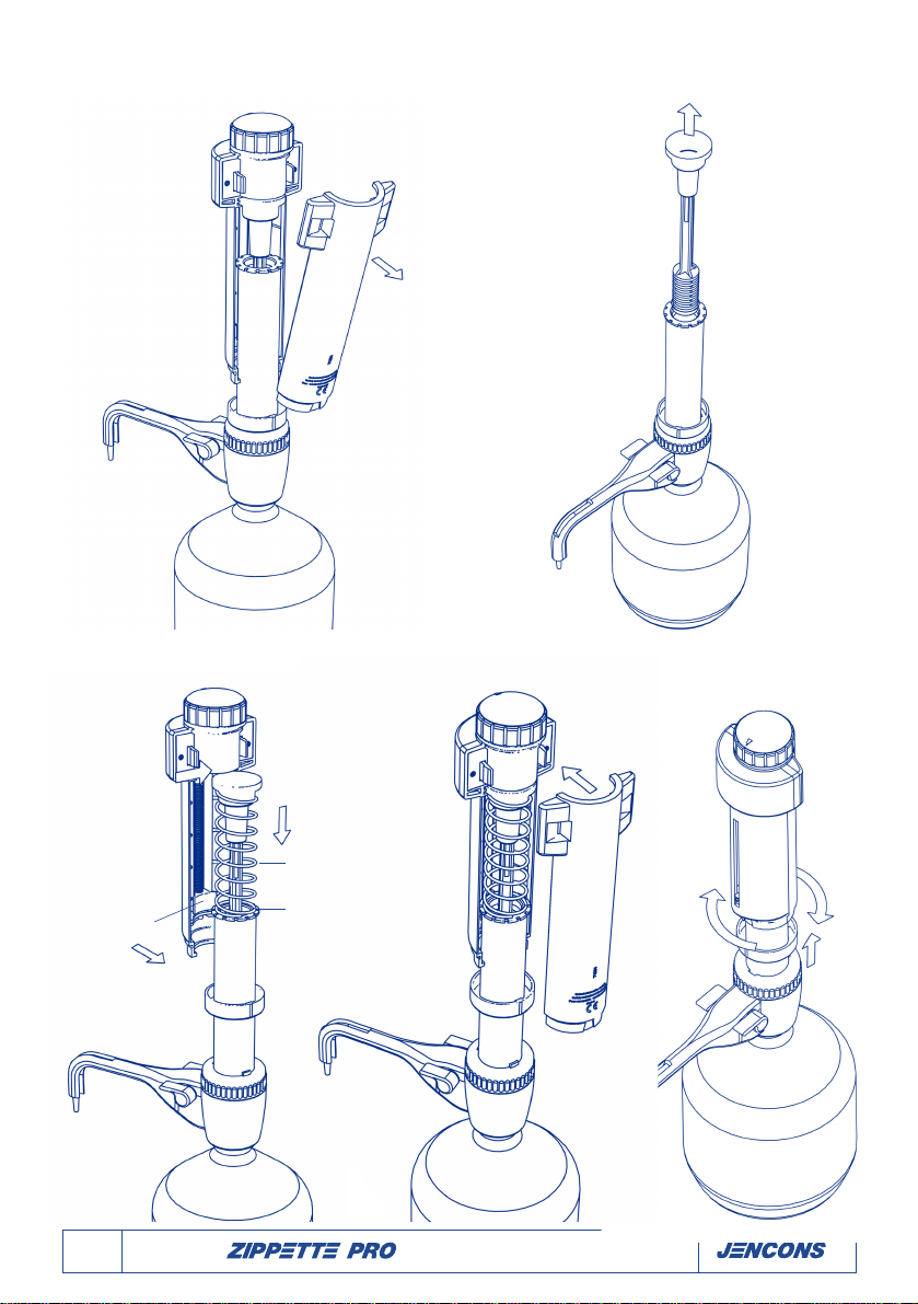
Inserting the return spring (when applicable)
To insert the return self-priming spring follow the following steps:
Drawing 1 Drawing 2
1. Make sure that the Zippette is completely
empty. For ease of operation, assemble the
Zippette onto an empty reservoir bottle and
turn the dispense anti-drip tap to ‘Open’
position.
2. Turn the volume adjustment knob, to set the
Zippette to the max dispense volume of 30ml
(Drawing 1).
3. Turn the fixing ring which is located at the bot-
tom of the Zippette’s piston sleeve until it’s
raised rib is aligned with the front piston sleeve
slot and remove by gently pulling down
(Drawing 1). The fixing ring should stay on the
barrel protection inner sleeve (Drawing 2).
4. Press the two fixing levers on the back of the
piston sleeve inwards (Drawing 2), and lever
the back piston sleeve away from the front
sleeve assembly (Drawing 3).
5. Remove the front sleeve assembly from the
piston locator and move the piston out of it’s
glass barrel (Drawing 3 & 4).
6. Carefully guide the piston through the spring,
and locate the piston back into it’s glass barrel
(Drawing 5).
7. Reassemble the front Zippette piston sleeve
(Drawing 5) making sure that the cursor
locates under the stop ring (Drawing 5).
8. Refit the back piston sleeve and pull up the
fixing ring (Drawing 6) – turn it half circle to
locate it onto the Zippette piston sleeve
(Drawing 7). The unit is now ready for use
(see operating instructions page 3).
Volume adjustment
knob
Front sleeve
Back sleeve Back sleeve
Fixing levers
Barrel
protection
sleeve
263-117
Cursor
Raised rib
Threaded platform ring
263-124
Fixing ring
263-081
Tap open position
Theaded
platform base
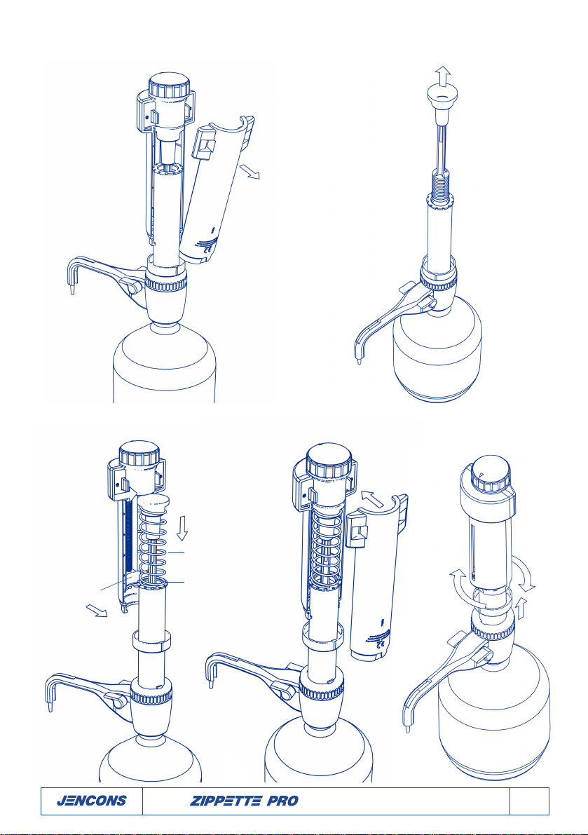
Drawing 3 Drawing 4
Drawing 5
Stop ring
263-103
Return spring
263-075
Cursor
Drawing 6 Drawing 7
Operator Instructions 5

6Operator Instructions
The volume adjustment knob
Turning the volume adjustment knob (Drawing 1) clockwise, will increase the volume to be dispensed. Each
full revolution of the knob represents 2ml and is shown on the cursor aligned to the graduations.
For fine volume adjustments, turn the knob a quarter turn in either direction for 0.5ml adjustment.
User Calibration procedure
Your Zippette Pro has been laboratory calibrated to it’s nominal volume of 30ml. However, due to changes in
environmental conditions and the viscosity of the media which you dispense, a recalibration might be
required. You can either recalibrate at regular intervals such as once a week or whenever you notice that the
dispensed volume is different from the volume displayed by the unit.
To fully recalibrate your Zippette Pro follow the following steps:
1. Set the Zippette Pro to the nominal volume of 30ml or any other volume which is the most common
volume you dispense.
2. Follow the common rules for calibration used in statistical quality control (ISO DIS 8655/2). Dispense
five full volumes of distilled water at 20°C to establish the actual mean volume of liquid dispensed. If
the gravitational average result varies from the volume displayed, you should recalibrate the Zippette.
3. Using a Cross Head screw driver no.00, slightly undo the cursor’s screw and move the cursor up or
down until it aligns with the graduation of the actual volume established in step 2.
Maintenance/Cleaning
Note; All maintenance should be carried out wearing suitable eye protection and protective clothing. If
in doubt, consult your safety officer.
1. Make sure that the Zippette is completely empty and turn the anti-drip tap to ‘Open’ position.
2. Place the instrument into an empty sink together with its reservoir. Unscrew the threaded platform
base from the reservoir and lift the dispenser’s intake tube carefully out of the reservoir, whilst tap-
ping it against the reservoir’s aperture to shake off any droplets from the intake tube.
3. Hold the dispense nozzle over the aperture of the reservoir and apply gentle piston strokes in order
to return any syringe contents into the reservoir.
4. Flush out remaining syringe contents with distilled water or a suitable solvent. This will preserve the
smooth action of the piston and free action of the inlet and outlet valves. If the inlet valve does stick
and is not freed by flushing, it may be freed by gently inserting a thin rod into the inlet aperture and
gently pushing the ball off its seating. Re-check unit for operation.
5. Empty the instrument completely after cleaning, and flush through with distilled water.

Operator Instructions 7
Sterilisation/Autoclaving
Only the fluid path components of the Zippette Pro are suitable for chemical sterilisation or autoclaving
at 121 °C after the normal cleaning procedure has been carried out.
Chemical sterilisation
The fluid path components of the Zippette can be soaked overnight in a dilute (1:1000) solution of
Sodium Hypochloride. (See page 8 for disassembly procedure).
For soaking the components individually, follow the fluid path disassembly instructions on the following
page.
Autoclaving
Autoclaving of fluid-path components is permissi-
ble at 121°C , 2 bar for 20 minutes, after the nor-
mal cleaning procedure has been carried out.
Autoclaving can be carried out only in a part
assembled condition with the piston inserted into
the glass barrel (Drawing 8) follow disassembly
instruction (page 8) 1 to 3 (Drawings 9-11). Steam
sterilisation of the piston outside the glass barrel
may damage it.
Loosen the threaded platform ring (Drawing 8) by
turning it anti clockwise two full revolutions.
Place the assembly together with the PTFE inlet on
a suitably soft surface within the autoclave in
order to avoid metal contact.
Cool slowly back to ambient temperature after
autoclaving and before assembly.
Drawing 8
Unit ready for steam
sterilisation
Threaded
platform ring

8Operator Instructions
Fluid-Path disassembly procedure for Cleaning or Replacement
Disassembly should only be undertaken AFTER the unit has been cleaned, using the standard cleaning
procedure described on page 6. For autoclaving follow steps 1-3.
1. Undo the piston sleeve fixing ring by turning it to align with the sleeve slot and sliding it down from
the sleeve (Drawing 9 & 10).
2. Press the two fixing levers on the back of the piston sleeve inwards, and lever the back piston sleeve
away from the front sleeve assembly (Drawing 10 & 11).
3. Remove the front piston sleeve (Drawing 12).
4. Pull out the piston assembly from the glass barrel (Drawing 13).
5. Undo the threaded platform ring of the base platform (Drawing 14) and, turn the stop ring clock-
wise and pull it off the assembly (Drawing 15).
6. Carefully slide off the fixing ring and the threaded platform ring, together with the clear
Polypropylene protection sleeve (Drawing 16).
7. Take out the glass barrel from the base platform. Under the glass barrel is an encapsulated FEP ‘O’
ring which should be handled with extreme care (Drawing 16).
8. To remove the FEP dispense tube (Drawing 17): firstly turn the anti-drip tap to the closed position
then lift off the dispense tube protective cover and pull out the dispense tube from its seating.
9. Reassemble the instrument following the above points in reverse order. Make sure that the FEP ‘O’
ring is well located into the base platform’s recess.
Important points to observe:
• Do not use hard tools to scrape off residue of reagent from the piston.
• Take special care not to damage the piston when inserting it into the glass barrel.
• Bevelled inside edge of the glass barrel must be at the top end when fitted.
• Before tightening the threaded ring fully onto the threaded platform base, rotate the Polypropylene
protection sleeve so that the tooth on its base locates properly into the notch on the threaded ring.
• Make sure the front end of the dispense tube is clipped into the dispense tube protection cover from
the underside
• Do not use force in assembly or disassembly
• Always wear protective clothing and eye protection when disassembling or assembling your Zippette.
Protective clothing and eye protection should also be worn when dispensing.

Operator Instructions 9
Drawing 9 Drawing 10
Drawing 11 Drawing 13
Fixing ring
263-081
Front sleeve
Back sleeve
Piston
assembly
263-076
Fixing ring
263-081
Fixing levers
Drawing 12

10 Operator Instructions10 Operator Instructions
Drawing 16
Drawing 14 Drawing 15
Threaded
platform ring
263-124
Stop ring
263-103
Platform
ring
263-124
Encapsulated
‘O’ ring
263-123
Zippette Pro pedestal
complete assembly
263-078
Fixing ring
263-081
Borosilicate
glass barrel
263-120
Protection
sleeve
263-117
FEP dispense tube
263-069
Dispense tube
protective cover
263-070
Anti-drip tap valve
Drawing 17

Operator Instructions 11
Problem Possible Cause Remedy
Air bubbles appear in discharge nozzle Liquid reservoir is empty Refill reservoir and prime unit
Too fast filling action Fill and dispense more slowly
Glass barrel is not sealing against FEP 'O' ring Unscrew the threaded platform ring and make sure that the
FEP 'O' ring is properly fitted into its recess
Leaking piston Clean piston. If problem persists, replace piston
Leaking discharge valve Clean unit by flushing through - if problem persists,
replace platform base
Barrel does not fill with liquid Inlet tube not fitted correctly Connect inlet tube correctly
Inlet valve stuck Free inlet valve by inserting a thin rod into the inlet aperture
Glass barrel is not sealing against the FEP 'O' ring Unscrew the threaded ring and make sure that the
FEP 'O' ring is properly fitted into its recess
Dispensing not possible Blocked dispense nozzle Disassemble the dispense nozzle and flush through
with cleaning fluid
Discharge valve stuck Clean unit by immersing platform in cleaning fluid
- if problem persists, replace platform base
Wrong dispense volume Instrument not calibrated See page 6 ‘User Calibration’
Leaking valves Clean platform base - if problem persists,replace
Liquid appears between glass barrel Glass barrel is not sealing against the Unscrew the threaded ring and make sure that the
and Polypropylene protection sleeve FEP 'O' ring FEP 'O' ring is properly fitted into its recess
Damaged FEP 'O' ring Replace FEP 'O' ring
Troubleshooting

12 Operator Instructions
Accessories
Adaptors
A range of five adaptors for fitting your dispenser to the reservoir are available.
Reservoirs
Description Cat. No.
1.4 litre 2-neck, amber Squat 262-086
2.5 litre 2-neck, amber Squat 262-103
2.5 litre 2-neck, amber Winchester 262-087
5 litre 2-neck, clear pyrex 262-088
2.5 litre single neck, clear glass, with 262-096
plastic coating, fingergrip handle
4.5 litre single neck, amber glass with plastic coating, 262-097
fingergrip handle and supplied with adaptor 222-000
Specification
Accuracy ≤±0.3% on maximum delivery and a precision ≤0.1%CV using distilled water at 20ºC.
30mm
33mm
30mm
38mm
30mm
40mm
30mm
45mm
30mm 115mm
262-140 262-129 262-128
262-130 262-084 262-085
B24/40 Angled funnel
Consignes d’utilisation 13
Sommaire
Consignes générales de sécurité . . . . . . . . . . . . . . . . . . . . . . . . . . . . . . . . . . . . . . . . . . . . . . . . . .Cette page
Consignes générales de sécurité . . . . . . . . . . . . . . . . . . . . . . . . . . . . . . . . . . . . . . . . . . . . . . . . . .Cette page
Restrictions d'utilisation . . . . . . . . . . . . . . . . . . . . . . . . . . . . . . . . . . . . . . . . . . . . . . . . . . . . . . . . . . . . . . .14
Avant d'utiliser la Zippette . . . . . . . . . . . . . . . . . . . . . . . . . . . . . . . . . . . . . . . . . . . . . . . . . . . . . . . . . . . . .14
Montage . . . . . . . . . . . . . . . . . . . . . . . . . . . . . . . . . . . . . . . . . . . . . . . . . . . . . . . . . . . . . . . . . . . . . . . . .14
Consignes d'utilisation . . . . . . . . . . . . . . . . . . . . . . . . . . . . . . . . . . . . . . . . . . . . . . . . . . . . . . . . . . . . . . . .14
Introduire le ressort de rappel . . . . . . . . . . . . . . . . . . . . . . . . . . . . . . . . . . . . . . . . . . . . . . . . . . . . . . . . . . 15
Le bouton de réglage du volume . . . . . . . . . . . . . . . . . . . . . . . . . . . . . . . . . . . . . . . . . . . . . . . . . . . . . . . .17
Calibrage personnalisé . . . . . . . . . . . . . . . . . . . . . . . . . . . . . . . . . . . . . . . . . . . . . . . . . . . . . . . . . . . . . . . .17
Entretien/Nettoyage . . . . . . . . . . . . . . . . . . . . . . . . . . . . . . . . . . . . . . . . . . . . . . . . . . . . . . . . . . . . . . . . . .17
Stérilisation/Stérilisation à l'autoclave . . . . . . . . . . . . . . . . . . . . . . . . . . . . . . . . . . . . . . . . . . . . . . . . . . . . .17
Procédure de démontage du circuit du soluté . . . . . . . . . . . . . . . . . . . . . . . . . . . . . . . . . . . . . . . . . . . . . . .19
Diagnostic des pannes . . . . . . . . . . . . . . . . . . . . . . . . . . . . . . . . . . . . . . . . . . . . . . . . . . . . . . . . . . . . . . .22
Accessoires . . . . . . . . . . . . . . . . . . . . . . . . . . . . . . . . . . . . . . . . . . . . . . . . . . . . . . . . . . . . . . . . . . . . . . .23
Soupape ouverte Soupape fermée
Consignes générales de sécurité
Ne laissez jamais la Zippette sur votre plan de travail avec le cylindre plein sans avoir correctement refer-
mé la soupape anti-goutte.
Vérifiez toujours que la soupape anti-goutte est sur la position 'Ouverte' avant toute utilisation.
• Avant de régler le volume, placez toujours le réservoir sous le pistolet et ouvrez la soupape
• Ne forcez jamais !

14 Consignes d’utilisation
Restrictions d'utilisation
N'utilisez JAMAIS la Zippette avec :
• Ses liquides qui ne sont pas compatibles avec le PTFE, PVDF, FEP, le verre borosilicate, la céramique
d'alumine ou qui sont susceptibles d'attaquer le platine iridié
• De l'acide fluorhydrique
• Des liquides contenant des particules solides
La Zippette et le réactif doivent être utilisés à des températures comprises entre 15°C et 40°C
Avant d'utiliser la Zippette
Vérifiez que l'appareil n'a pas été endommagé pendant le transport.
Montage
La Zippette est livrée avec le pistolet de distribution monté et le tube d'admission non monté. Ce tube
en PTFE d'une longueur de 300mm devra être coupé pour être adapté à votre réservoir personnel. Le
tube doit être coupé en diagonale à son extrémité inférieure, à une longueur proche du fond du récipi-
ent lorsque la Zippette est en place. Des tubes d'admission plus longs sont disponibles sur demande.
La base de plate-forme filetée de la Zippette possède un collet de vis de 30mm qui doit être utilisé avec
le réservoir ambré de sécurité Jencons de 1,4 litres avec un col de remplissage latéral (Cat. No 262-086)
ou avec le réservoir ambré de 2,5 litres (Cat No 262-103). La Zippette assemblée se fixe sur le réservoir
en vissant uniquement la base filetée avec précaution. Il doit être retiré en dévissant uniquement la base.
N'actionnez pas le piston tant que l'appareil n'est pas monté correctement sur le réservoir !
Trois adaptateurs sont fournis pour des récipients avec des collets de vis de 38mm, 40mm ou 45mm.
Consignes d'utilisation
Amorçage du réservoir
• Placez un récipient sous le pistolet de distribution de la Zippette
• Tournez le bouton de réglage du volume sur 30ml pour permettre un mouvement libre du piston
• Ouvrez la soupape anti-gouttes
• Amorcez l'appareil en appuyant plusieurs fois, en descendant le piston jusqu'à sa position d'arrêt la
plus basse et en le relevant d'environ 25mm
• Recommencez l'opération jusqu'à ce que le flux s'écoule en continu et ne présente aucune bulle

Consignes d’utilisation 15
Introduire le ressort de rappel (le cas échéant)
Pour introduire le ressort de rappel à amorçage automatique, suivez les étapes suivantes :
Illustration 1 Illustration 2
1. Vérifiez que la Zippette est entièrement vide.
Pour faciliter l'opération, montez la Zippette
sur un réservoir vide et mettez la soupape
anti-gouttes sur la position "Ouverte".
2. Tournez le bouton de réglage du volume pour
régler la Zippette sur le volume de distribution
de 30ml (illustration 1).
3. Tournez la bague de fixation qui se trouve au
bas du manchon du piston de la Zippette
jusqu'à ce que sa rainure bombée soit alignée
avec la fente du manchon du piston avant et
enlevez en tirant doucement (Illustration 1).
La bague de fixation doit rester sur le man-
chon de protection du cylindre (Illustration 2).
4. Enfoncez les deux leviers de fixation au dos du
manchon du piston vers l'intérieur (Illustration
2) et écartez le manchon du piston arrière du
manchon avant (Illustration 3).
5. Démontez le manchon avant du dispositif de
positionnement du piston et sortez le piston
de son cylindre en verre (Illustrations 3 et 4).
6. Guidez avec précaution le piston au travers du
ressort et remettez le piston dans son cylindre
en verre (Illustration 5).
7. Réassemblez le manchon du piston de la
Zippette (Illustration 5) en vous assurant que
le curseur est placé au-dessous de la bague
de butée (Illustration 5).
8. Remettez le manchon du piston en place et
remontez la bague de fixation (Illustration 6) -
Tournez-la d'un demi-tour pour la placer sur
le manchon du piston de la Zippette
(Illustration 7). L'unité est prête à l'emploi
(voir les consignes d'utilisation page 14).
Bouton de réglage du
volume
Manchon avant
Manchon arrièr Manchon arrière
Leviers de
fixation
Manchon de
protection
de cylindre
263-117
Curseur
Nervure bombée
Bague de plate-forme
filetée 263-124
Bague de fixation
263-081
Position ouverte
de soupape
Base de
plate-forme
filetée
16 Consignes d’utilisation
Illustration 3 Illustration 4
Illustration 5
Bague d'arrêt
263-103
Ressort de rappel
263-075
Curseur
Curseur
Illustration 6 Illustration 7

Consignes d’utilisation 17
Le bouton de réglage du volume
Si vous tournez le bouton de réglage vers la droite (Illustration 1), vous augmentez le volume distribué.
Chaque tour complet du bouton représente 2 ml et apparaît sur le curseur aligné avec les graduations.
Pour effectuer un réglage précis, tournez le bouton d'un quart de tour pour obtenir un réglage de
0,5ml.
Calibrage personnalisé
Votre Zippette Pro a été étalonnée en laboratoire pour un volume nominal de 30 ml. Cependant, à cause
du changement des conditions environnementales et de la variabilité de la viscosité du milieu que vous
distribuez, un nouveau calibrage peut s'avérer nécessaire. Vous pouvez recalibrer à des intervalles
réguliers comme une fois par semaine où à chaque fois que vous remarquez que le volume distribué est
différent du volume affiché par l'unité.
Pour recalibrer votre Zippette Pro, veuillez suivre la procédure suivante :
1. Réglez la Zippette Pro sur le volume nominal de 30 ml ou tout autre volume qui représente le volume
que vous utilisez le plus souvent.
2. Suivez les règles de calibrage utilisées dans le contrôle de qualité statistique (ISO DIS 8655/2)
Distribuez cinq doses complètes d'eau distillée à 20°C pour établir le volume moyen de liquide dis-
tribué. Si le résultat moyen gravitationnel varie par rapport au volume affiché, vous devez calibrer de
nouveau l'appareil.
3. A l'aide d'un tournevis cruciforme no 00, dévissez légèrement la vis du curseur et remontez ou abais-
sez le curseur jusqu'à ce qu'il soit aligné avec la graduation du volume établi à l'étape 2.
Entretien/Nettoyage
Remarque: toute opération d'entretien doit être réalisée en portant des vêtements et des lunettes de
protection adaptés. En cas de doute, consultez le responsable de la sécurité.
1. Vérifiez que la Zippette est entièrement vide et tournez la soupape anti-gouttes sur la position
'Ouverte'.
2. Mettez l'appareil avec son réservoir dans un évier. Desserrez la base filetée et retirez avec précaution
le tube d'admission du réservoir en le tapant doucement contre l'ouverture afin d'en faire tomber les
dernières gouttelettes.
3. Placez le pistolet de distribution au-dessus de l'ouverture du réservoir et appuyez doucement sur le
piston afin de faire couler le liquide.
4. Rincez le reste du contenu de la seringue avec de l'eau distillée ou un solvant adapté. Ceci préservera
la souplesse du piston et le fonctionnement des soupapes d'aspiration et de distribution. Si la
soupape d'aspiration est toujours bouchée après le rinçage, elle peut être débouchée en insérant
doucement un mince bâtonnet dans l'ouverture de la soupape et en déplaçant lentement la bille.
Vérifiez que l'appareil fonctionne correctement.
5. Videz complètement l'appareil après le nettoyage et rincez à l'eau distillée.

18 Consignes d’utilisation
Stérilisation/Stérilisation à l'autoclave
Une stérilisation chimique ou à l'autoclave à 121°C est possible uniquement pour les composants du cir-
cuit du soluté, après la procédure de nettoyage standard.
Stérilisation chimique
Une stérilisation chimique peut être faite en laissant tremper les composants du circuit du soluté pendant
une nuit dans une solution diluée (1:1000) d'hypochlorure de sodium. (Voir la page 8 pour la procédure
de démontage).
Pour faire tremper les composants individuellement, suivez les consignes de démontage à la page suivante.
Autoclave
Une stérilisation à l'autoclave des composants du
circuit du soluté est possible à 121°C, 2 bars pen-
dant 20 minutes, après la procédure de nettoyage
standard.
La stérilisation à l'autoclave peut être réalisée
uniquement dans un état de semi-assemblage
avec le piston inséré dans
le cylindre en verre (Illustration 8). Suivez la con-
signe de démontage (page 8) 1 à 3 (Illustrations 9-
11). Une stérilisation à la vapeur du piston à l'ex-
térieur du cylindre risque de l'endommager.
Desserrez la bague de plate-forme filetée
(Illustration 8) en la tournant de 2 tours vers la
gauche.
Placez l'assemblage et l'admission PTFE sur une
surface douce dans l'autoclave afin d'éviter tout
contact métallique.
Laissez refroidir lentement à la température
ambiante après la stérilisation à l'autoclave, avant
l'assemblage.
Illustration 8
Appareil prêt à la
stérilisation à la vapeur
Bague de
plate-forme
filetée

Consignes d’utilisation 19
Procédure de démontage du circuit du soluté pour le nettoyage
ou le remplacement
Le démontage ne doit être fait qu'APRES le nettoyage de l'appareil suivant la procédure standard décrite
à la page 6. Pour la stérilisation par autoclave, suivez les étapes 1-3.
1. Retirez la bague de fixation du manchon du piston en le faisant tourner afin de l'aligner avec la fente
du manchon et en la faisant glisser (Illustrations 9 et 10).
2. Enfoncez les deux leviers de fixation au dos du manchon du piston vers l'intérieur et écartez le man-
chon du piston arrière du manchon avant (Illustrations 10 et 11).
3. Enlevez le manchon du piston avant (Illustration 12).
4. Retirez le piston du cylindre en verre (Illustration 13).
5. Démontez la bague de la plate-forme filetée de la plate-forme de base (Illustration 14) et tournez la
bague d'arrêt vers la droite et retirez-la de l'assemblage (schéma 15).
6. Faites glisser doucement la bague de fixation et la bague de plate-forme filetée, ainsi que le man-
chon de protection en polypropylène (Illustration 16).
7. Détachez le cylindre en verre de la plate-forme de base. Prenez bien garde de ne pas perdre le joint
torique en FEP qui est monté à l'intérieur de la base (Illustration 16).
8. Pour démonter le tube de distribution en FEP (Illustration 17) : Tout d'abord, mettez la soupape anti-
gouttes sur la position fermée et retirez le couvercle de protection du tube puis sortez le tube.
9. Réassemblez l'instrument en suivant la procédure donnée ci-dessus dans l'ordre inverse. Vérifiez que
le joint torique en FEP se trouve bien dans le renfoncement de la plate-forme de base.
Points importants à respecter :
• N'utilisez pas des outils coupants pour gratter les résidus de réactif du piston.
• Prenez soin de ne pas endommager le piston lorsque vous l'introduisez dans le cylindre en verre.
• L'extrémité biseautée du cylindre doit être en haut lorsqu'il est en place.
• Avant de resserrer entièrement la bague filetée sur la base de la plate-forme filetée, faites tourner le
manchon de protection en polypropylène de façon à ce que les dents de sa base entrent correcte-
ment dans l'entaille de la bague filetée.
• Vérifiez que l'extrémité avant du tube de distribution est attaché sur le couvercle de protection du
tube de distribution par le dessous
• N'appliquez aucune force au cours de l'assemblage ou du démontage
• Portez toujours des vêtements de protection et des lunettes de sécurité lors de l'assemblage ou du
démontage de la Zippette. Des vêtements protecteurs et des lunettes doivent aussi être portés lors
de la distribution.
Table of contents
Languages:
Other JENCONS Dispenser manuals


Popular Dispenser manuals by other brands


U-Line
U-Line TORK H-7177 Mounting instructions

Samoa
Samoa 325 000 Assembly

Hilti
Hilti HIT-P 8000 D operating instructions

START International
START International Tape TDA150 quick start guide

Philips
Philips ADD6920 user manual

Silver King
Silver King Majestic SK10MAJ Technical manual and replacement parts list