Consignes d’utilisation 19
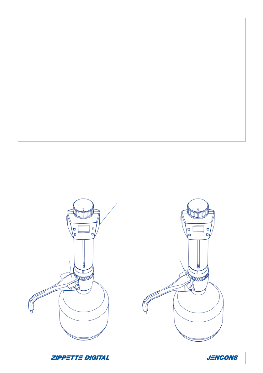
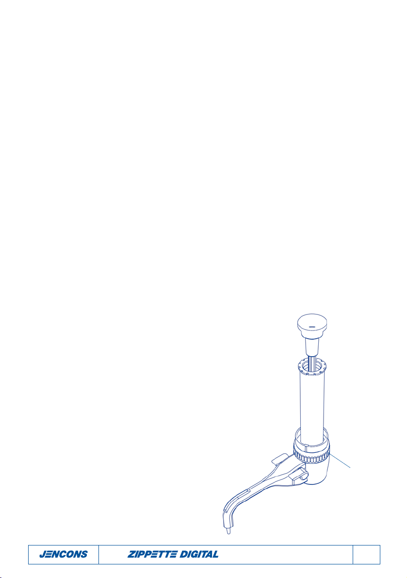
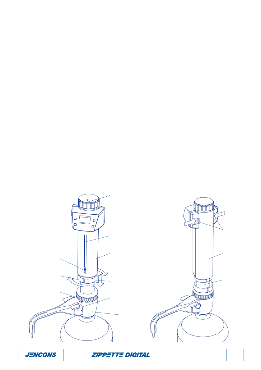
Le bouton de réglage du volume
Si vous tournez le bouton de réglage vers la droite, vous augmentez le volume distribué. Chaque tour
complet du bouton représente 2ml.
Pour effectuer un réglage précis, tournez le bouton d'un quart de tour pour obtenir un réglage de 0,5ml.
Calibrage personnalisé
Votre Zippette Digital a été étalonnée pour un volume nominal de 30 ml. Cependant, à cause du
changement des conditions environnementales et de la variabilité de la viscosité du milieu que vous dis-
tribuez, un nouveau calibrage peut s'avérer nécessaire. Vous pouvez recalibrer à des intervalles réguliers
comme une fois par semaine où à chaque fois que vous remarquez que le volume distribué est différent
du volume affiché par l'unité.
Pour recalibrer votre Zippette Digital, veuillez suivre la procédure suivante :
1. Réglez la Zippette Digital sur le volume nominal de 30 ml ou tout autre
volume qui représente le volume que vous utilisez le plus souvent.
2. Suivez les règles de calibrage utilisées dans le contrôle de qualité statis-
tique (ISO DIS 8655/2) Distribuez cinq doses complètes d'eau distillée à
20°C pour établir le volume moyen de liquide distribué. La formule ci-
jointe vous permettra de suivre des règles de base. Si le résultat moyen
gravitationnel varie par rapport au volume affiché, vous devez calibrer
de nouveau l'appareil.
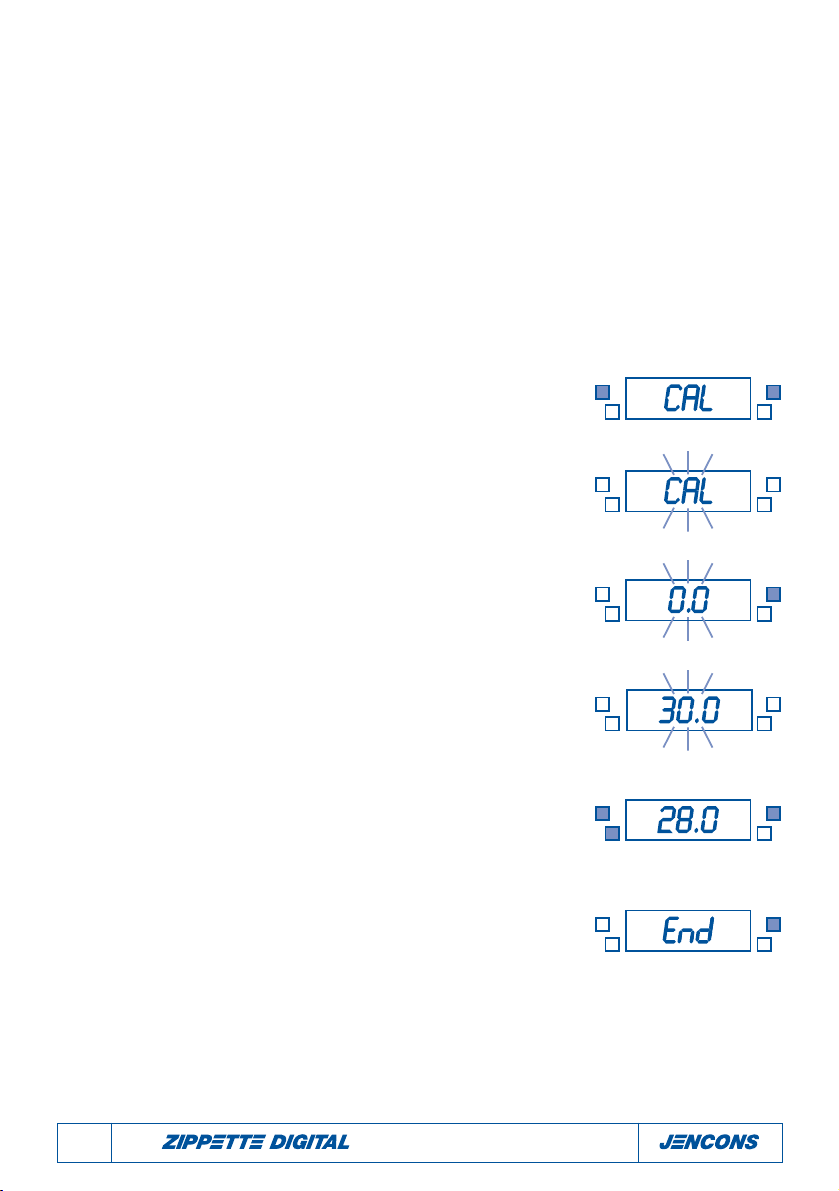
3. Enfoncez simultanément les boutons 'CAL' et 'UP' pendant 5 minutes
afin d'activer le mode de calibrage de l'instrument. Dès que vous êtes
en mode calibrage, le mot CAL se met à clignoter sur l'écran.
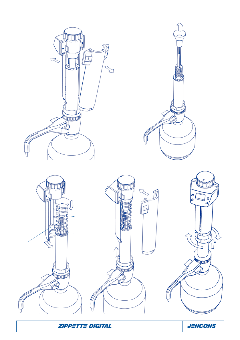
4. Alors que le mot CAL clignote, mettez le piston dans sa position d'arrêt la
plus basse. Si votre Zippette est équipée d'un ressort, maintenez le piston
dans sa position la plus basse et tournez le bouton de réglage du volume
doucement vers la gauche, sur une position qui ne permet pas un mou-
vement axial du piston. NE FORCEZ PAS ! Ceci est votre position '0'.
5. Appuyez de nouveau sur le bouton CAL - L'affichage présente 0.0 par
défaut.
6. A partir de cette position '0', alors que l'écran affiche par intermittence
le volume 0.0, tournez le bouton de réglage du volume pour afficher le
volume nominal qui a servi à établir le volume réel.
7. Dès que l'appareil affiche le volume nominal, appuyez sur 'CAL'.
L'écran s'arrête de clignoter. A l'aide des flèches haut et bas, corrélez le
volume de l'affichage avec le volume réel qui a été établi dans la procé-
dure gravitationnelle.
8. Appuyez de nouveau sur le bouton 'CAL'. L'affichage présente le mot 'end'
pour indiquer que la procédure de calibrage a été effectuée avec succès.
Si vous souhaitez terminer la procédure de calibrage avant la fin, appuyez
sur le bouton 'On'. L'affichage présente 'Esc' pendant deux secondes pour
indiquer que vous avez quitté la procédure et l'écran retourne au volume
que la Zippette est prête à distribuer.
3.
4.
5.
6.
7.
8.