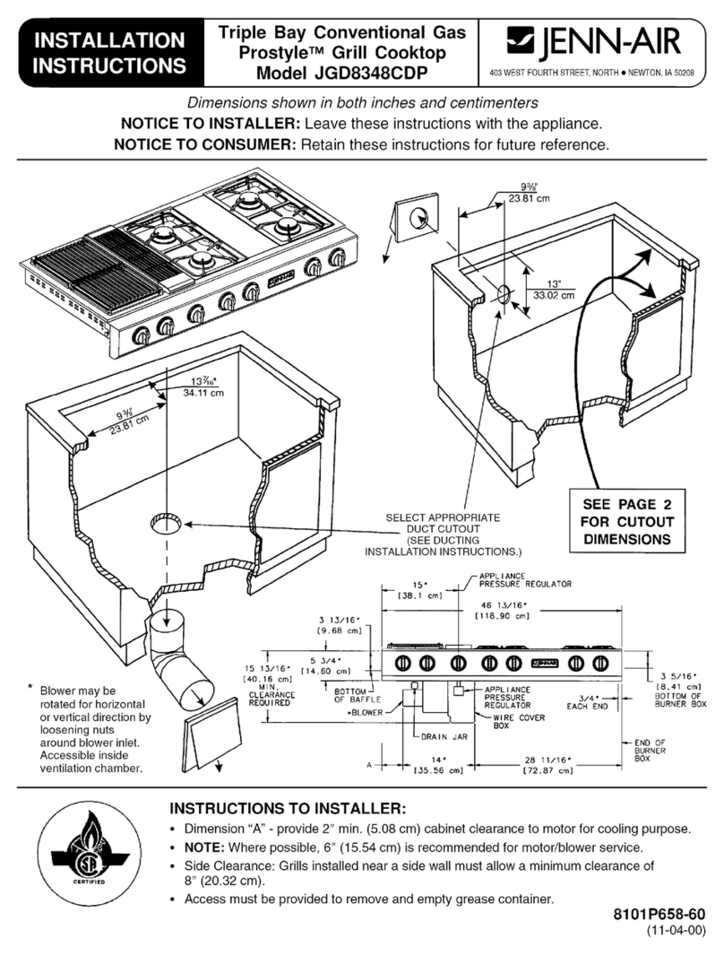
Electrical Wiring Information
The neutral of this unit is grounded to the frame
through the green grounding wire. If local conditions
do not permit grounding of the neutral, untwist or
disconnect the green wire and connect the green
wire to ground in accordance with local codes.
Connect the white neutral to the service neutral.
A = 30" (76.2 cm) MifJimum clearance be-
tween the top of the cooktop and the bot-
tom of an unprotected wood or metal
cabinet.
A = 24" (60.96 cm) Minimum when bottom
of wood or metal cabinet is protected t>y
not less than 1/4" (0.635 cm). FLAME
RETARDANT millboard covered with not
less than no. 28 MSG sheet steel, 0.01 !5"
(0.038 cm) stainless steel, 0.024" (0.OEi1
cm) aluminum or copper.
You must provide an adequate electrical supply
system as required for your cooktop. All wire
connections must be in accordance with local codes
and properly insulated. Check with local utility for
governing electrical codes and ordinances. In the
absence of local electrical codes, the National
Electrical Code, NFPA No. 70, governing electric
range installations must be followed. A copy of the
National Electrical Code, NFPA No. 70, can be
obtained by writing to:
~
Dottedlines
indicate
rangehood
constructionk---
A*
.L~-- I National Fire Protection Association
Batterymarch Park
Quincy, Massachusetts 02269
*To eliminate the risk of burns or fire by reach-
ing over heated surface units, cabinet stor-
age space located above the surface units
should be avoided. If cabinet storage is to
be provided, the risk can be reduced by irl-
stalling a range hood that projects horizorl-
tally a minimum of 5 inches beyond the bo1:-
tom of the cabinets.
A three-wire, single phase, A.C. 120/240 volt 60
cycle electrical system (properly circuit protected to
meet Local Codes of NFPA No. 70) must be pro-
vided. Unit must be properly grounded in accor-
dance with local wiring code. The chart below
recommends the minimum circuit protector and wire
size if the appliance is the only unit on the circuit. If
smaller sizes of wire are used, the unit efficiency will
be reduced and a fire hazard may be created. It is
advisable that the electrical wiring and hookup be
accomplished by a competent electrician.
Installer Installation Suggestions
0 -4.9
5.0 -6.9
7.0 -9.9
10.0 -11.9
12.0 -14.9
20
30
40
50
60
12
10
8
8
6
1. Chamfer all exposed edges of decorative lami-
nate to prevent damage from chipping.
2. Radius corners of cutout and file to insure smooth
edges and prevent corner cracking.
3. Rough edges, inside corners which have not t>een
rounded and forced fits can contribute to crac:king
of the countertop laminate.
4. Countertop must be supported within 3" (7.62 cm)
of cutout.
2
