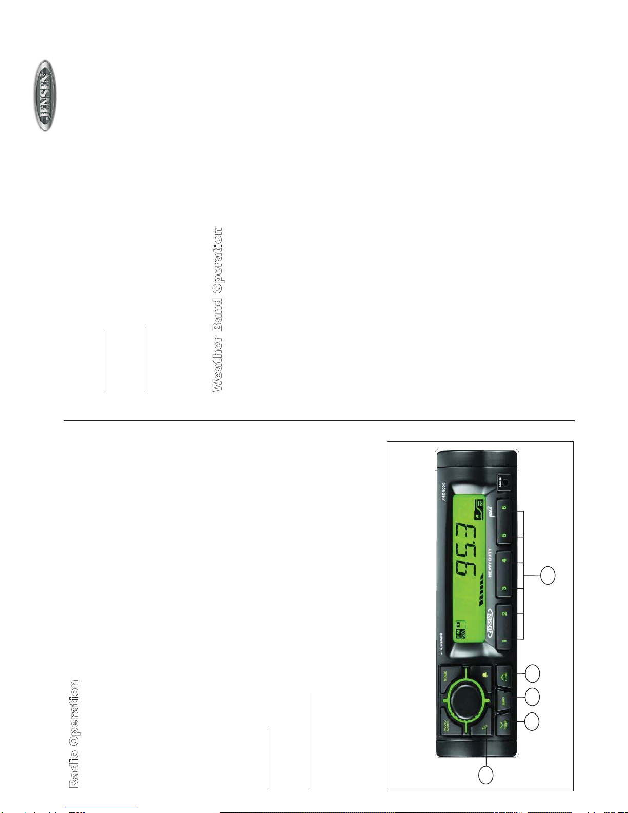
manuals.online logo
Brands
  1. Home
  2. •
  3. Brands
  4. •
  5. Jensen
  6. •
  7. Car Receiver
  8. •
  9. Jensen JHD1000 User manual

Jensen JHD1000 User manual

JHD1000
System Features
Features of the Jensen JHD1000 mobile audio system include:
• AM/FM Tuner with 18 Presets (6 AM, 12 FM)
• Weatherband Tuner
• Programmable World Tuner
• Alarm Clock Function
• Two or Four Speaker Setup Option
• Front Panel Auxiliary Input
• Electronic Bass, Treble, Balance and Fader Controls
• Output Power 4x30W
Installation
Content List
• Jensen Main Chassis
• Hardware Kit
• Wiring Harness
• Male to male 3.5mm stereo plug patch cord
• Installation Manual
Hardware Kit
DIN Radio Installation
This unit is designed for installation in vehicle cabs with an existing radio opening. In many cases,
a special installation kit will be required to mount the radio to the dashboard. These kits are
available at electronics supply stores and car stereo specialist shops. Always check the kit
application before purchasing to make sure the kit works with your vehicle.
Owner’s Manual
Thank You!
Thank you for choosing a Jensen product. We hope you will find the instructions in this owner’s manual
clear and easy to follow. If you take a few minutes to look through it, you’ll learn how to use all the
features of your new Jensen receiver for maximum enjoyment.
System Features. . . . . . . . . . . . . . . . . . . . . . . . . . . . . . . . . . . . . . . . . . . . . . . . . . . . . . . . . . 1
Installation. . . . . . . . . . . . . . . . . . . . . . . . . . . . . . . . . . . . . . . . . . . . . . . . . . . . . . . . . . . . . . . 1
Configuration . . . . . . . . . . . . . . . . . . . . . . . . . . . . . . . . . . . . . . . . . . . . . . . . . . . . . . . . . . . . 2
Wiring. . . . . . . . . . . . . . . . . . . . . . . . . . . . . . . . . . . . . . . . . . . . . . . . . . . . . . . . . . . . . . . . . . . 3
Basic Operation . . . . . . . . . . . . . . . . . . . . . . . . . . . . . . . . . . . . . . . . . . . . . . . . . . . . . . . . . . 4
Radio Operation . . . . . . . . . . . . . . . . . . . . . . . . . . . . . . . . . . . . . . . . . . . . . . . . . . . . . . . . . . 5
Weather Band Operation . . . . . . . . . . . . . . . . . . . . . . . . . . . . . . . . . . . . . . . . . . . . . . . . . . . 5
Troubleshooting . . . . . . . . . . . . . . . . . . . . . . . . . . . . . . . . . . . . . . . . . . . . . . . . . . . . . . . . . . 6
Specifications . . . . . . . . . . . . . . . . . . . . . . . . . . . . . . . . . . . . . . . . . . . . . . . . . . . . . . . . . . . . 6
MOUNTING SCREW
REMOVAL TOOL
DIN SLEEVE
MOUNTING BUSHING
MOUNTING STRAP
FLANGE NUTS 10AMP
1AMP
JHD1000
2
Installation (continued)
Universal Installation (Using Mounting Sleeve)
1) Remove endcaps and slide the mounting sleeve off of the chassis. If it is locked into position,
use the removal tools (supplied) to disengage it.
2) Check the dashboard opening size by sliding the mounting sleeve into it. If the opening is not
large enough, carefully cut or file as necessary until the sleeve slides easily into the opening. Do
not force the sleeve into the opening or cause it to bend or bow. Check that there will be sufficient
space behind the dashboard for the radio chassis. Connect wires prior to actually installing the
sleeve. Pigtail wiring should take place after hole size is confirmed. Mount sleeve after wiring.
3) Follow the wiring diagram carefully and make certain all connections of the wiring harness are
properly secured and insulated to insure proper operation of this unit. After completing the wiring
connections, turn the unit on to confirm operation (ignition switch must be "on"). If unit does not
operate, recheck all wiring until the problem is corrected. Once proper operation is achieved, turn
off ignition switch and proceed with final mounting of the chassis.
4) Locate the series of bend tabs along the top, bottom, and sides of the mounting sleeve. With
the sleeve fully inserted into the dash opening, bend tabs outward so that the sleeve is firmly
secured to the dashboard.
5) Carefully slide the radio into the mounting sleeve making sure it is right side up until it is fully
seated and the spring clips lock it into place.
6) Attach one end of the perforated mounting strap (supplied) to the screw stud on the rear of the
chassis using the flange nut provided. Fasten the other end of the perforated strap to a secure
part of the dashboard, either above or below the radio using the screw and flange nut provided,
bend the strap to position as necessary.
CAUTION: The rear of the radio must be supported with the strap to prevent damage to the
dashboard from the weight of the radio or improper operation due to vibration.
Kit Installation
1. If your radio requires the use of an installation kit to mount this radio, follow the instructions
included in the kit to attach the radio to the mounting plate supplied with the kit.
2. Wire and test the radio as described.
3. Install the radio/mounting plate assembly to the sub-dash according to the instructions of the
installation kit.
4. Attach the support strap to the radio and dashboard as described in step 6 on page 2.
5. Replace the dashboard trim panel.
Configuration
The radio can be programmed to change options and factory settings. Follow the steps that follow
to modify the unit as required.
Configuration of the Clock Display (12 or 24 Hour)
Press AUDIO ADJUST for more than three seconds. The unit will enter the general configuration
menu and display CL-24 or CL-12. To select 12 hour clock operation, press the up tuning button
once or until CL-12 is displayed. If 24-hour clock operation is desired, press the up tuning button
until CL-24 is displayed. To exit, press AUDIO ADJUST again or the configuration menu time out
(takes about five seconds).
Configuration of Auxiliary Low-Level Audio Input
Press AUDIO ADJUST for more than three seconds. The unit will enter the general configuration
menu. To configure the radio to accept low-level audio signal, scroll through menu items until
"AUX--**" (where ** can equal Y or N) is displayed. Use the up tuning button to change the option
to "AUX-Y". To disable this feature, use the up tuning button to change back to "AUX-N". To exit,
press AUDIO ADJUST again or the configuration menu time out (takes about five seconds).
Note: If this feature is disabled, the front panel jack will also be disabled.
MOUNTING
SURFACE
MOUNTING
SLEEVE
BEND TABS BOTTOM TAB
BEND DOWNWARD 90°
MOUNTING TAB DETAILS
CUTAWAY VIEW OF
MOUNTING SURFACE SIDE VIEW
TOP TAB BEND
UPWARD 90°
JHD1000
3
PINK (TRIGGER) - SEE CHART C
GREEN/WHITE (BATTERY +12V) - SEE CHART A
LEVEL AUDIO INPUT
SEEPAGE4FORLOW
BLACK/WHITE (GROUND)
DIN CONNECTOR
9PINCABLE
CONNECTOR
TO ANTENNA
4PINCABLE
CONNECTOR
GRAY (-)
GRAY/BLUE (+)
ORANGE/WHITE (ACC. +12V) - SEE CHART B
LEFT FRONT SPEAKER
4OR8OHM
GRAY/WHITE (+)
G RA Y (-)
LEFT REAR SPEAKER
4OR8OHM
GRAY (-)
RIGHT REAR SPEAKER
4OR8OHM
GRAY/YELLOW (+)GRAY/RED (+)
RIGHT FRONT SPEAKER
GRAY (-)
4OR8OHM
WITH RESPECTIVE POSITIVES
*SOLDER AND TAPE ALL SPLICES
*SPEAKER WIRES ARE BONDED PAIRS
NEGATIVE GRAY WIRES PAIRED
Wiring Color Codes
From 9-Pin
Harness
From 4-Pin
Harness
Gray
Gray/White
Orange/White
Black
Pink
Green/White
Gray
Gray/Blue
Gray
Gray/Yellow
Gray
Gray/Red
Left Front (-)
Left Front (+)
Ignition
Chassis Ground
12V Out 100mA
Memory
Right Front (-)
Right Front (+)
Right Rear (-)
Right Rear (+)
Left Rear (-)
Left Rear (+)
2-Bond Pair
2-Bond Pair
2-Bond Pair
2-Bond Pair
Wiring
The wiring diagram depicts all the wiring connections required for proper operation of the unit.
Configuration (continued)
Configuration of the World Band Tuner
Press AUDIO ADJUST for more than three seconds. The unit will enter the general configuration
menu. To enter the tuner configuration menu, press preset 4, then preset 2. "CC--**" will appear
on the display (where ** can equal 11, 12, 14, 15, 16 or 21). Use the up tuning button to select
the proper country code for the region of interest. The country codes are listed above. To exit,
press AUDIO ADJUST again or the configuration menu time out (takes about five seconds).
Configuration of 2 and 4 Speaker Operation
Press AUDIO ADJUST for more than three seconds. The unit will enter the general configuration
menu. Press the up tuning button until "SP--**" appears in the display (where ** can equal 2 or 4).
Change this menu item according to the desired setup by using the up tuning button to modify
the setting to either "SP-2" or "SP-4". To exit, press AUDIO ADJUST again or the configuration
menu time out (takes about five seconds).
Configuration of Tuner Seek Sensitivity Setting
The scan sensitivity feature is designed to give flexibility during the tuner seek function. The
tuner can be configured such that during seek, it will stop on strong stations, ignoring weaker
signals. The tuner can also be configured to stop at all weak signals.
To configure the seek sensitivity setting, press AUDIO ADJUST for more than three seconds.
The unit will enter the general configuration menu. While in the general configuration menu,
press preset 4 and then preset 2. The unit is now in the tuner configuration menu. Press the up
tuning button until "SC--**" appears in the display (where ** can equal 00-15). The numbers are
set such that at the setting "SC-00", the unit is more sensitive to weaker signals. This means that
the seek function will stop at most or all weak signals. At "SC-15", the seek function will stop only
at the strong stations. Use the up tuning button to adjust the seek sensitivity of the tuner to a
setting that will suit the application. To exit, press AUDIO ADJUST again or the configuration
menu time out (takes about five seconds)..
Country Code Country Band Low High Step
11 North America AM
FM 530
87.9 1710
107.9 10kHz
200kHz
12 Europe SW
AM
FM
LW
5900
531
87.50
144
6200
1629
108.00
288
5kHz
9kHz
50kHz
9kHz
13 Pacific AM
FM 531
87.5 1629
108.0 9kHz
100kHz
14 Japan AM
FM 522
76.0 1629
90.0 9kHz
100kHz
15 Latin America AM
FM 530
88.0 1600
108.0 10kHz
100kHz
16 Brazil AM
FM 530
87.9 1620
107.9 10kHz
200kHz
21 Saudi Arabia AM
FM 531
87.5 1602
108.0 9kHz
50kZHz
JHD1000
4
AUX IN
123 456
HEAVY DUTY
TUNE BAND TUNE
AUDIO
ADJUST
MODE
TF
/
PUSH POWER
JHD1000
1&4 3
52
6a
6b 6c 78
Basic Operation
1. Power
Press the power button (1) to turn the unit on or off.
2. Liquid Crystal Display
The Liquid Crystal Display (LCD) panel (2) displays the frequency, time and activated functions.
3. Mode
Press MODE (3) to select a different mode of operation as indicated on the display panel.
Available modes include radio band and auxiliary input (AUX).
4. Volume
To adjust the volume, rotate the volume control knob (4) clockwise (to increase volume) or
counter clockwise (to decrease volume).
5. Sound Adjustment
Press AUDIO ADJUST (5) repeatedly to step through the following sound adjustment options:
Bass, Treble, Balance (left to right) and Fader (front to rear). When the desired option appears
in the display, rotate the volume control knob to adjust that audio feature. When no adjustments
have been made for five seconds, the unit will resume normal operation.
Note: There is no fader adjustment option during 2-speaker operation.
6. Setting the Clock
To set the clock to display the current time, turn the vehicle ignition on and turn the radio off.
Press T/F (6a) for more than one second, and the time will flash in the display. Press the down
tuning button (6b) to adjust the hours or the up tuning button (6c) to adjust the minutes. “A” or
“P” will appear on the display to indicate AM or PM. When no adjustment is made for five
seconds, the time will be set and normal operation will resume.
7. Alarm Clock Function
Setting the Alarm Clock
This unit has an alarm clock function that can be set to turn the unit on at a specific time. To set
the alarm clock, turn the vehicle ignition on and turn the radio off. Press the alarm button (7) for
longer than one second, and the time will flash in the display. Press the down tuning button (6b)
to adjust the hours or the up tuning button (6c) to adjust the minutes. “A” or “P” will appear on
the display to indicate AM or PM. When no adjustment is made for five seconds, the time will be
set and normal operation will resume.
Alarm Clock On/Off Selector
Press the alarm button momentarily to turn the alarm function on or off. The bell symbol will
appear in the display when the alarm function is on. To check the time for which the alarm is set,
press the alarm button for more than one second, and the time will flash in the display. After five
seconds, the display will stop flashing and the unit will return to normal operation.
Note: When the alarm feature is activated, the unit will turn on even if the ignition is off.
The mode of operation (radio or auxiliary input) and volume level that were last used will
be automatically recalled. The unit will automatically turn itself off after five minutes.
8. Auxiliary Input Function
Insert a standard 3.5 mm (audio line output or headphone output from your portable CD / MP3 /
iPod or other media player) into the "AUX-IN" jack (8) on the front of the unit. If your media
player does not include an audio out cabled, use the Aux Cable included with this unit.
Basic Operation
JHD1000
5
AUX IN
123 456
HEAVY DUTY
TUNE BAND TUNE
AUDIO
ADJUST
MODE
TF
/
PUSH POWER
JHD1000
10
911b
11a
12
Radio Operation
9. Select a Band
Press BAND (9) to change between two FM bands (FM1 and FM2), one AM band (AM) and the
weather band (WTHR). When an FM stereo broadcase is being received, the ST indication will
appear in the display. If operating the unit in areas outside North America, the band designation
may include LW or SW, and the weather function may be disabled.
10. Time/Frequency Selector (T/F)
Press T/F (10) to select whether the clock time or radio frequency/playback functions will appear
in the display. When the time is selected as the priority setting, the display will automatically
return to the time display five seconds after any radio, auxiliary or audio function is displayed.
When the frequency setting is selected, the display will automatically return to the time display
five seconds after any radio, auxiliary or audio function is displayed.
11. Tuning
Manual Tuning
Press the up tuning button (11a) or down tuning button (11b) momentarily to tune the frequency
one step higher or lower.
Automatic Seek Tuning
Press the up or down tuning button for more than one second, and the radio will seek the next
available strong station. Alternately, press and continue to hold a tuning button to tune rapidly in
the selected direction. When the button is released, the unit will seek the next strong station.
Note: Seek tuning is not available for weather band channels. Use the up or down tuning
buttons to manually select any of the seven available weather band channels.
12. Preset Stations
Six numbered preset buttons (12) store and recall stations for each band.
Store a Station
Select a band (if needed), then select a station. Hold a preset button for three seconds. The
current station will be stored, and the corresponding preset number will appear in the display.
Recall a Station
Select a band (if needed). Press a preset button momentarily, and the unit will tune to the
corresponding stored station.
Note: Preset buttons will not function in weather band mode.
Weather Band Operation
What is the NOAA Weather Radio/Weatheradio Canada?
This is a nationwide system that broadcasts local weather emergency information 24 hours a day. The
U.S. network has more than 530 stations covering the 50 states as well as the adjacent costal waters,
Puerto Rico, the U.S. Virgin Islands and the U.S. Pacific Territories. Each local area has its own
transmitting station and there are a total of seven broadcasting frequencies used. A similar system is
available in Canada under the Weatheradio Canada service administered by Environment Canada.
HowmanystationscanIexpecttoreceive?
Since the broadcasts are local weather and information, the transmission power is usually very low
(much less than standard AM or FM stations) so you will usually receive only one station unless you
are on the edge of two or more broadcast signals. The most you will receive will be two or three, and
that is rare.
Is it possible I won't receive any stations?
Depending on where you are located, there is a possibility you will receive only a very weak signal or
none at all. Also, similar to AM and FM signals, weatherband signals are subject to surrounding
conditions, weather, obstructions of the signal by hills or mountains, etc.
How will I know I am tuned to Weatherband?
When you select the weather band, the indication "WTHR" will appear on the display panel, along with
the current channel indication: "CH1", CH2", "CH3", "CH4", "CH5", "CH6" or "CH7". Use the up and
down tuning buttons to tune to each of the seven channels until you find the weatherband station
broadcasting in your area.
Radio Operation
JHD1000
6
Troubleshooting
Problem Cause Corrective Action
No power. Vehicle ignition switch is not
on. If the power supply is connected to
the vehicle accessory circuits but
the engine is not moving, switch the
ignition key to “ACC”.
The fuse is blown. Replace the fuse.
No sound. Volume turned down too low. Adjust volume until sound is heard.
Wiring not connected properly. Check wiring connections.
Radio does not work Antenna cable not connected. Insert antenna cable firmly.
Specifications
General
Power Supply Requirements . . . . . . . . . . . . . . . . . . . . . . . . . DC 12 Volts, Negative Ground
Chassis Dimensions. . . . . . . . . . . . . . . . . . . . . . . . . . . . . . . . . . . 178 (W) x 178 (D) x 50 (H)
Loading Impedance . . . . . . . . . . . . . . . . . . . . . . . . . . . . . . . . . . . . . . 4 -8 ohms per channel
Tone Controls . . . . . . . . . . . . . . . . . . . Bass (at 100 Hz), ±10 dB; Treble (at 10 kHz), ±10 dB
Current Drain . . . . . . . . . . . . . . . . . . . . . . . . . . . . . . . . . . . . . . . . . . . . . . . . 7 Ampere (max.)
FM Tuner
Tuning range. . . . . . . . . . . . . . . . . . . . . . . . . . . . . . . . . . . . . . . . . . . . . . . . . . . . . .87.5-108.0
FM mono sensitivity . . . . . . . . . . . . . . . . . . . . . . . . . . . . . . . . . . . . . . . . . . . . . . . . . . . .1.5uV
Stereo separation @ 1 kHz. . . . . . . . . . . . . . . . . . . . . . . . . . . . . . . . . . . . . . . . . . . . . . >25dB
AM Tuner
Tuning range. . . . . . . . . . . . . . . . . . . . . . . . . . . . . . . . . . . . . . . . . . . . . . . . . . . . . . .522-1710
Amplifier
Total system power. . . . . . . . . . . . . . . . . . . . . . . . . . . . . . . . . . . . . . . . . . . . 120W (30W x 4)
Specifications subject to change without notice.
www.asaelectronics.com
© 2006 ASA Electronics Corporation
v.040506

Other Jensen Car Receiver manuals

Jensen CMR3710 Operating instructions

Jensen

Jensen CMR3710 Operating instructions

Jensen JCD2006 User manual

Jensen

Jensen JCD2006 User manual

Jensen VX3012 User manual

Jensen

Jensen VX3012 User manual

Jensen VM9411 User manual

Jensen

Jensen VM9411 User manual

Jensen BT1613 User manual

Jensen

Jensen BT1613 User manual

Jensen cd3010x User manual

Jensen

Jensen cd3010x User manual

Jensen VM8113R User manual

Jensen

Jensen VM8113R User manual

Jensen VX3010 User manual

Jensen

Jensen VX3010 User manual

Jensen VM9214BT User manual

Jensen

Jensen VM9214BT User manual

Jensen VX4010 User manual

Jensen

Jensen VX4010 User manual

Jensen AWM975 User manual

Jensen

Jensen AWM975 User manual

Jensen VX7020A User manual

Jensen

Jensen VX7020A User manual

Jensen VX7010 User manual

Jensen

Jensen VX7010 User manual

Jensen VM8023HD - DVD Receiver User manual

Jensen

Jensen VM8023HD - DVD Receiver User manual

Jensen VX7020A User manual

Jensen

Jensen VX7020A User manual

Jensen JDV8035 User manual

Jensen

Jensen JDV8035 User manual

Jensen HR9000PKG User manual

Jensen

Jensen HR9000PKG User manual

Jensen HR9000PKG User manual

Jensen

Jensen HR9000PKG User manual

Jensen JCDWIN User manual

Jensen

Jensen JCDWIN User manual

Jensen JCKFM1 User manual

Jensen

Jensen JCKFM1 User manual

Jensen VX3010 User manual

Jensen

Jensen VX3010 User manual

Jensen MP6512i User manual

Jensen

Jensen MP6512i User manual

Jensen JBR550PKG User manual

Jensen

Jensen JBR550PKG User manual

Jensen VM9312HD - DVD Player With LCD Monitor User manual

Jensen

Jensen VM9312HD - DVD Player With LCD Monitor User manual

Popular Car Receiver manuals by other brands

iRV Technologies iRV 34 Operation manual

iRV Technologies

iRV Technologies iRV 34 Operation manual

Panasonic CQ-D5501W Service manual

Panasonic

Panasonic CQ-D5501W Service manual

Kenwood KRC-101 instruction manual

Kenwood

Kenwood KRC-101 instruction manual

Kenwood KVT911DVD - Mobile DVD/CD Player instruction manual

Kenwood

Kenwood KVT911DVD - Mobile DVD/CD Player instruction manual

Dual ZDMR7710 Installation & owner's manual

Dual

Dual ZDMR7710 Installation & owner's manual

Blaupunkt CALGARY MP36 installation instructions

Blaupunkt

Blaupunkt CALGARY MP36 installation instructions

Sony XR-2753 operating instructions

Sony

Sony XR-2753 operating instructions

Clarion CZ209E owner's manual

Clarion

Clarion CZ209E owner's manual

Pioneer DEH-P980BT - Premier Radio / CD Operation manual

Pioneer

Pioneer DEH-P980BT - Premier Radio / CD Operation manual

JVC KD-G322 Installation & connection manual

JVC

JVC KD-G322 Installation & connection manual

Pioneer DEH-P6000UB - Radio / CD installation manual

Pioneer

Pioneer DEH-P6000UB - Radio / CD installation manual

Clarion CX501A owner's manual

Clarion

Clarion CX501A owner's manual

JVC KD-G537 Installation & connection manual

JVC

JVC KD-G537 Installation & connection manual

NAD C715 Service manual

NAD

NAD C715 Service manual

Sony CDX-SW200 - Fm/am Compact Disc Player operating instructions

Sony

Sony CDX-SW200 - Fm/am Compact Disc Player operating instructions

Sony CDX-C570R operating instructions

Sony

Sony CDX-C570R operating instructions

Sanyo EXCD-1000 operating instructions

Sanyo

Sanyo EXCD-1000 operating instructions

AEG CS MP 300 owner's manual

AEG

AEG CS MP 300 owner's manual

manuals.online logo
manuals.online logoBrands
  • About & Mission
  • Contact us
  • Privacy Policy
  • Terms and Conditions

Copyright 2025 Manuals.Online. All Rights Reserved.