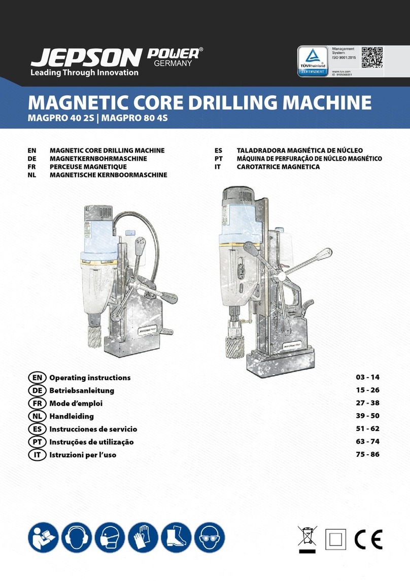
Jepson MAGPRO TP 2000 User manual

MAGPRO TP 2000
1 of 10
Instruction Manual Magnetic Core Drill English 14
MAGPRO TP 2000

MAGPRO TP2000
Page 2 of 10
Index
1EG-CONFORMITY DECLARATION.................................2
2USER INSTRUCTIONS....................................................3
3SAFETY INSTRUCTIONS................................................3
3.1 Illustration of Safety Instructions.....................................3
3.2 General Safety Instructions............................................3
3.2.1 Work Area Safety..................................................4
3.2.2 Electrical Safety....................................................4
3.2.3 Personal Safety ....................................................4
3.2.4 Tool use and care.................................................4
3.2.5 Service .................................................................5
3.3 Specific Safety Rules.....................................................5
3.4 Symbols on the Electric Tool.........................................5
4MACHINE DESCRIPTION................................................5
4.1 Identification Data..........................................................5
4.2 Intended Use .................................................................5
4.3 Transport and Storage...................................................6
4.4 Functional Description....................................................6
5INSTALLATION, COMMISSIONING AND TRANSPORT..6
5.1 Assembling and Components ........................................6
5.2 Technical Data...............................................................6
5.3 Assembly / Mounting.....................................................6
5.4 SPECIAL INSTRUCTIONS FOR
AUTO-REVERSE TAPPING MODELS.........................7
5.4.1 Setting up for tapping ........................................... 7
5.4.2 Setting the depth meter........................................7
5.4.3 Setting the travel limter stop................................. 8
5.4.4 8
5.4.5 Tapping operation ................................................8
5.4.6 Settin gup for twist drilling..................................... 8
5.4.7 Setting up for annular cutters................................9
6MAINTENANCE AND REPAIR ........................................9
6.1 Cleaning........................................................................9
6.2 Maintenance..................................................................9
6.2.1 The arbor Shaft ....................................................9
6.2.2 The Gibs (Dovetail slides).....................................9
6.2.3 Carbon Brushes ...................................................9
6.3 Repairs........................................................................10
6.4 Troubleshooting........................................................... 10
7DECOMMISSIONING AND DISPOSAL ......................... 10
8REPLACEMENT AND WEAR PARTS............................ 10
1 EG-Conformity Declaration
(according to Appendix IIA of the machine Directive)
We, Routexport Agencies SA
Visserijstraat 25, rue de la Pêcherie
1180 Brüssel
Belgien
as the manufacturer declare herewith under our responsibility that the product:
Name:
MAGPRO TP2000
Serial No. :
Manufacturing Date:
2009
complies with the following standards, directives and referenced standard documents:
2006/42/EC
2014/30/EU
2006/95/EC
Machinery
Low Voltage
Electromagnetic Compatibility
EN 61029-1:2009+A11:2010
EN 62233:2008
EN 55014-1:2006+A1:2009+A2:2011
EN 55014-2:1997+A1:2001+A2:2008
EN 61000-3-2:2014
EN 61000-3-3:2013
Pierre Michiels, Managing Director
Name, Position Brussels, 01.01.2019

MAGPRO TP2000
Page 3 of 10
2 User Instructions
Notes for the customer
The instruction manual includes important instructions as to how
to operate the plant safely, correctly and economically. Observ-
ing these instructions helps to avoid risks, repair costs and
downtimes and to increase the reliability and lifetime of the
machine.
The instruction manual must be read and used by each person
who works with the electrical equipment. This applies in particu-
lar to the "Safety Instructions" chapter. It is too late to read the
manual and safety instructions when work is actually being
carried out at the machine.
Always keep one copy of this manual next to the machine so
that it is at hand ready to be consulted!
In case of any doubt or questions, always contact the machine
manufacturer.
In addition to the instruction manual, the accident prevention
regulations which apply in the country of use and the user loca-
tion must be adhered to. In addition, the recognised technical
rules regarding accident prevention must be observed.
Liability and warranty
All the information contained in this instruction manual has been
drawn up to the best of our knowledge and belief, taking our
experience to date into consideration.
The original version of this instruction manual was drawn up in
the German language and was checked by us for accuracy of
content. The translation into the respective national/contractual
language was carried out by a recognised translation agency.
This instruction manual has been put together with the greatest
of care. However, if you should discover any incomplete items or
mistakes, please inform us in writing. Your suggestions for
improvement will help us to create a user-friendly manual.
Subsequent Orders and Copyright
Further copies of this instruction manual can be ordered from
the address below. We ask for your understanding that further
copies are subject to charge.
Jepson Elektrowerkzeuge
Ernst-Abbe-Straße 5
D-52249 Eschweiler
Phone: +49 (0)2403 – 6455-0
Fax: +49 (0)2403 – 6455-15
Mail: [email protected]
All rights are expressly reserved. Duplication or transfer on to
third parties in any form whatsoever is not allowed without our
prior written permission.
Abbreviations
V Volt
Hz Hertz
W Watt
~ AC
/min Revolutions per minute rpm
N Newton
3 Safety Instructions
The basic prerequisite for safe handling and disturbance-free
operation of this electric tool is knowledge of the basic safety
instructions. In addition, the accident prevention rules and regu-
lations which apply in the user location must be adhered to, as
well as the recognised rules of the trade with regard to safety
and correct working methods.
It is not permitted to use the electric tool for other purposes than
those intended by the manufacturer. Such use could give rise to
unforeseeable risks.
Local working and safety rules and laws must always be fol-
lowed. The same applies to regulations which apply to the envi-
ronment.
Safety equipment must never by removed or bridged over.
When using oils, greases and other chemical substances, the
safety regulations which apply to the particular product must
always be observed! Contact with chemicals should be avoided
as far as possible. Before it is permissible to work with these
substances the instructions for use on the packaging must be
read and followed. This applies for all chemicals, therefore also
for cleaning media.
All notes and signs regarding safety and possible risks must be
kept in a fully legible condition.
3.1 Illustration of Safety Instructions
The following symbols are used in the instruction manual:
Warning against possible danger of injury or
danger to life for persons
Warning
Warning against possible damage to property or
the environment
Caution
Warning against dangerous electrical voltage
Warning against hot surfaces
Ignoring these instructions can lead to serious damage to
health, up to life-threatening injuries!
This symbol indicates important information
Hazardous to the environment
3.2 General Safety Instructions
This electric tool fulfils the basic EC safety
and health regulations. Nevertheless, dan-
gerous situations can arise.
Warning
All safety equipment must be maintained in
perfect condition.
Warning

MAGPRO 35
4 of 10
Always pay attention to moving parts.
These can cause injury because of their
movement or by sudden movement.
Warning
Only use the electric tool when it is in
perfect condition from the technical point
of view, and only use it for intended pur-
pose while being aware of safety issues
and risks, and paying attention to the
instruction manual! In particular, have any
disturbances which could have a negative
effect on safety corrected immediately!
WARNING! It is essential to read all the instructions. Mis-
takes which are made while attempting to follow the below
instructions can cause electric shock, fire and/or serious
injury. The following term "Electric tool", refers to mains-
powered electric tools (with mains cable) and battery-
powered electric tools (without mains cable).
Warning Caution
KEEP THESE INSTRUCTIONS IN A SAFE
PLACE.
3.2.1 Work Area Safety
Keep your work area clean and well lit. Cluttered benches
and dark areas invite accidents.
Do not operate power tools in explosive atmospheres, such
as in the presence of flammable liquid, gases, or dust.
Power tools create sparks, which may ignite the dust or fumes.
Keep bystanders, children, and visitors away while operat-
ing a power tool. Distractions can cause you to lose control.
3.2.2 Electrical Safety
Warning Caution
Earthed tools must be plugged into an outlet properly in-
stalled and earthed in accordance with all codes and ordi-
nances. Never remove the earthing prong or modify the
plug in any way. Do not use any adaptor plugs. Check with
a qualified electrician if you are in doubt as to whether the
outlet is properly earthed. If the tools should electrically mal-
function or break down, earthing provides a low resistance path
to carry electricity away from the user.
Avoid body contact with earthed or grounded surfaces
such as pipes, radiators, ranges and refrigerators. There is
an increased risk of electric shock if your body is earthed or
grounded.
Don’t expose power tools to rain or wet conditions. Water
entering a power tool will increase the risk of electric shock.
Don’t abuse the cord. Never use the cord to carry the tools
or pull the plug from an outlet. Keep cord away from heat,
oil, sharp edges or moving parts. Replace damaged cords
immediately. Damaged or entangled cords increase the risk of
electric shock.
When operating a power tool outside, only use authorized
cords for out door work. These cords are rated for outdoor
use and reduce the risk of electric shock.
3.2.3 Personal Safety
Stay alert, watch what you are doing and use common sense
when operating a power tool. Do not use tool while tired or
under the influence of drugs, alcohol, or medication. A mo-
ment of inattention while operating power tools may result in
serious personal injury.
Use safety equipment. Always wear eye protection. Safety
equipment such as dust mask, non-skid safety shoes, hardhat, or
hearing protection used for appropriate conditions will reduce
personal injuries.
Avoid accidental starting. Be sure switch is off before plug-
ging in. Carrying tools with your finger on the switch or plugging
in tools that have the switch on invites accidents..
Warning Caution
Remove any adjusting key or wrenches before turning the
tool on. A wrench or a key that is left attached to a rotating part
of the tool may result in personal injury.
Do not overreach. Keep a proper footing and balance at all
times. Proper footing and balance enables better control of the
tool in unexpected situations.
Dress properly. Do not wear loose clothing or jewellery.
Keep your hair, clothing and gloves away from moving
parts. Loose clothes, jewellery or long hair can be caught in
moving parts.
3.2.4 Tool use and care
Do not force tool. Use the correct tool for your application.
The correct tool will do the job better and safer at the rate for
which it is designed.
Do not use tool if switch does not turn it on and off. Any tool
that cannot be controlled with the switch is dangerous and must
be repaired.
Disconnect the plug from the power source before making
any adjustments, changing accessories, or storing the tool.
Such preventive safety measures reduce the risk of starting the
tool accidentally.
Store idle tools out of reach of children and do not allow
persons unfamiliar with the power tool or these instructions
to operate the power tool. Tools are dangerous in the hands of
untrained users.
Maintain tools with care. Keep cutting tools sharp and
clean. Properly maintained tools, with sharp cutting edges are
less likely to bind and are easier to control.
Maintain power tools. Check for misalignment or binding of
moving parts, breakage of parts, and any other condition
that may affect the tools operation. If damaged, have the
tool serviced before using. Poorly maintained tools cause
many accidents.
Use the power tool, accessories and blades etc., in accord-
ance with these instructions and in the manner intended for
the particular type of power tool, taking into account the
working conditions and the work to be performed. Use of
the power tool for operations different from those intended could
result in a hazardous situation.
Use clamps or other practical way to secure and support
the work piece to a stable platform. Holding the work by hand
r against your body is unstable and may lead to loss of control.

MAGPRO 35
5 of 10
Use only accessories that are recommended by the manu-
facturer for your model. Accessories that may be suitable for
one tool may become hazardous when used on another tool.
Warning Caution
3.2.5 Service
Only qualified repair personnel must perform tool service.
Service or maintenance performed by unqualified personnel
could result in a risk of injury.
When servicing tool, use only identical replacement parts.
Follow instructions in the Maintenance section of this man-
ual. Use of unauthorized parts or failure to follow Maintenance
Instructions may create a risk of electric shock or injury.
3.3 Specific Safety Rules
Warning Caution
Take care to avoid the magnet releasing. Ensure that the
magnet has properly adhered to the work piece before begin-
ning drilling.
Metal swart and other debris will dangerously lower mag-
nets adhesion force. Always ensure that the magnet is clean
and free of rust or other foreign matter.
Employ safety chain at all times. Magnet can release unex-
pectedly at any time- especially due to power failure.
Power supply socket must be kept easily accessible. In an
emergency you may need to quickly unplug the machine.
Never exceed an angle of 90 degrees. Overhead (upside
down) drilling is very dangerous and should never be attempted.
The magnets adhesion depends on the thickness of the
work piece. Always ensure that the work piece is a mini-
mum of 12mm (7/16 in.) thick. If not, then a minimum 10mm
thick piece of iron or steel must be placed under the workpiece
to ensure adequate adhesion.
Other electric machines used on the same receptacle will
cause uneven voltage, which could lead to the magnet
releasing. Always use this machine alone on the receptacle.
Avoid operating annular cutters without coolant fluid. Al-
ways check coolant level before operating.
Do not operate with blunt or damaged cutting tools. This will
easily overload the motor.
Protect the motor. Never allow cutting fluid, water, or other
foreign contaminants enter the motor.
Metal swarf are often very sharp and hot. Never touch them
with bare hands. Clean up with a magnetic swarf collector and
a chip hook or other appropriate tool.
CAUTION: NEVER position machine on a workpiece be-
tween the electrode and the earth an arc type welder. Dam-
age to the machine will result, as the welder will earth
through the machines earthing cable.
Warning Caution
WARNING: NEVER attempt to use machine with incorrect
current or abnormally low voltage. Check machine name-
plate to ensure that correct voltage and Hz are used.
Extension cable should be selected after ensuring the di-
ameter is sufficient for the length. Follow the chart below:
Max length:
10m (32 ft.) 1.25 square mm (16 ga.)
15m (50 ft.). 2.0 square mm (14 ga.)
30m (100 ft.) 3.50 square mm (12 ga.)
(Over 30m NOT RECOMMENDED)
Never touch the rotating cutter or swarf with your bare
hands, body, gloves, hair or clothing.
When replacing cutters never touch the sharp cutting sur-
faces with bare hands
Use a pilot pin, which matches the cutter. A mismatched
cutter and pilot pin will cause a dangerous situation.
Non-ferrous metals and other materials may not be used,
since the magnet will not be able to adhere to it magnetical-
ly.
Do not use excessive feed pressure when drilling.
3.4 Symbols on the Electric
Tool
Warning against dangerous electrical voltage
Warning against high surface temperature
4 Machine Description
4.1 Identification Data
The following information is shown on the Identification/Type
plate:
Model
Serial number
Maximum power
Weight
Connected load
4.2 Intended Use
The magnetic drill may only be used as intended by the manu-
facturer, as described in this instruction manual. Any other use
than the use described is not the intended or proper use. The
manufacturer shall not be responsible for any damage resulting
from such unintended or improper use.
The magnetic drill is constructed according to the latest state of
technology and is operationally safe if the instructions contained
in this manual and the relevant and valid national safety rules
and regulations are followed.
Nevertheless, danger for life and limb of the user or third parties
can arise during use, along with damage to machine and other
property.
Only use the magnetic drill when it is technically perfect condi-
tion and only use it for its intended use! Be aware of safety
factors and possible risks and always following the instructions
in the instruction manual! Have any disturbances or faults which
could have a negative effect on safety repaired immediately by
our customer service department!
The manufacturer shall not be responsible in any way whatso-
ever for:
Non-observance or insufficient observance of the information in
this instruction manual;

MAGPRO 35
6 of 10
Use of replacement parts or parts which are not approved by
the manufacturer;
Incorrect operation;
Removal, manipulation or non-use of safety or protective
equipment;
Change of function;
Changes to the magnetic drill;
Incorrect repair or maintenance;
Unintended or improper use.
Foreseeable incorrect operation
The magnetic drill can be dangerous if it not used correctly or
not used for its intended purpose.
The instruction manual must be available at all times when the
machine is use and over the entire period of operation of the
machine. Keep this instruction manual together with the magnet-
ic drill!
The magnetic drill is only guaranteed safe to use if used correct-
ly and for its intended purpose. The limit values which are stated
may not be exceeded under any circumstances whatsoever.
The information and instructions in the operat-
ing manual must be followed without fail! The
manufacturer shall not be responsible and the
warranty of the manufacturer shall lapse if the
magnetic drill is used in any other way than
described in the manual.
Caution
Hazardous substances must be disposed of so
that there is no risk to persons or the environ-
ment. Leakage of hazardous substances leads
to hazard to the environment. The relevant legal
regulations must be observed.
4.3 Transport and Storage
Dispose of packaging and insulation in a
proper and environmentally-friendly fashion.
Observe the relevant national rules and
regulations.
Store the magnetic drill in such a way that
damage is avoided.
Caution
Store the magnetic drill complete with all
individual parts and accessories, as other-
wise important parts could be missing when
the machine is recommissioned.
Caution
Use the transport box for transportation and
storage.
4.4 Functional Description
The magnetic drill adheres to mild non-alloy steel and works
with a drill motor which is attached to a stand.
Either a core drill or a twist drill is used (accessories).
5 Installation, Commissioning and
Transport
5.1 Assembling and Components
1. Brush cap
2. Crank handle
3. Mode selector for shifting to Auto-reverse tapping mode
or standard drilling mode)
4. Quick release collar
5. Tap collet arbor
6. Tap (not included)
7. Travel limiter stop
8. Gib adjuster screw
9. Magnet
10. Magnet switch
11. Motor Swich
12. Coolant feed tap
13. Coolant tank
14. Lock Knob
15. Adjustable pointer
16. Depth meter scale
5.2 Technical Data
Drill motor unit
230V 50Hz
Power input
1100 W
Drilling Mode (No / Full load speed)
550 / 330 rpm
Tapping Mode (No / Full load speed)
150 / 190 rpm
Total Stroke
150 mm
Magnetic Adhesion
15.000 N
Net weight
13,7 kg
Generation of noise (Lpa)
89 +/- 0,5 db (A)
Generation of noise (Lwa)
100 +/- 0,5 db (A)
Hand-Arm-Vibration
2,4 +/- 0,5 m/s
2
Cut. max. diameter x depth
35 x 55 mm
Core Drills
Up to Ø 35 mm
Core Drill adapter Weldon shank , set
screw type
Taps
M12 to M20
5.3 Assembly / Mounting
1
2
3
4
5
6
7
8
9
10
11
12
13
14
15
16

MAGPRO 35
7 of 10
We recommend inspecting all the items delivered for complete-
ness and any transport damage. Complaints are generally only
accepted if they are registered on the day they are received.
Assembly of coolant tank
First attach clear tube to the bottom of the coolant tank. To do
this, first loosen the nut and slide nut onto the tube. Then slide
tube onto the nipple. Then tighten the nut.
Slide tank hanger over the screw on the upper right hand side of
slide and tighten.
Finally insert the other end of the tube into the connector in the
gearbox. Just directly push in to install. (To remove, first firmly
push the collar of the connector and pull the tube out.)
Cutting coolant fluid is always required when using annular
cutters. Open tank cover and fill. Check coolant fluid level often.
Keep coolant tap closed when not in use. Empty coolant tank
when returning the machine to the carry case.
Chip guard must be used. To attach the chip guard,
use the sup-plied butterfly bolts to bolt to the magnet. It
is not necessary to remove guard to clean chips. Simply
raise guard to its upper position.
Warning
Safety chain must be used. Loop chain around the
work piece and feed through the machines handle and
clip in place. MOUNTING ANNULAR CUTTERS:
CAUTION: Never use a cutting tool, which is larger than
the maximum rated capacity of the machine.
Warning
5.4 SPECIAL INSTRUCTIONS FOR
AUTO-REVERSE TAPPING
MODELS
THIS MACHINE IS THE FIRST OF ITS KIND SO
SPECIAL CARE MUST BE PAID TO THE
OPERATING INSTRUCTIONS BELOW TO
UNDERSTAND ITS TAPPING FUNCTION.
CAUTION: Before beginning tapping en
sure that
the hole is the correct size for the tap. An under-
size hole will cause the tap to jam causing a
hazardous situation.
CAUTION: When tapping a blind hole always
correctly use the travel limiter stop to ensure
that there is enough clearance so that you do
not bottom-
out the tap. Bottoming will cause
the tap to jam, causing a hazardous situation.
CAUTION: Never attempt to tap with the gear-
box selector in standard drilling mode.
The much higher speed of the standard drilling
mode will damage the tap and cause a hazardous
situation .
COOLING: The automatic through the spindle cooling
function is only effective when using annular cutters.
When tapping or using twist drills, cutting oil must be
added manually.
5.4.1 Setting up for tapping
CAUTION: Never use a cutting tool which is larger
than the maximum rated capacity of the machine.
CAUTION:: Always follow the tap manufacturer ’ s
recommendation for selecting the correct size hole
for tapping.
CAUTION: Never attempt to change gears on a
running machine! Only change gears when the
Caution
machine is at rest.
1.
Select the correct sized Tap Collet
Arbor for the tap which you intend
to use. If there is already another
arbor in the machine, simply push
up on the Quick-Release Collar and
remove.
2. To insert the Arbor, push up on the
Quick-
Release Collar (1) and insert
the Arbor (2). Turn the Arbor until
the tangs line up and the Collar is
able to close. Ensure that it is se-
curely in place.
3.
Insert the tap into the Tap Collet
Arbor. Push up on the tap and turn
it until it snaps in place. When it is
time to remove the tap from the Ar-
bor, depress the Release Ring (3)
on the Arbor. (Catch the tap so that
it does not fall
on the floor when it
releases.)
4. If it is in drilling mode, shift the gearbox to tapping mode by swing-
ing the gear selector tab out of the detent slot then shifting down-
wards into tapping mode. Then pop the selector tab back into the
detent . It will sometimes be necessary to turn the spindle by hand
a little to get it to shift all the way. Only grab the arbor when turn-
ing the spindle, never the quick-release collar. Otherwise, it will be
easy to accidentally release the arbor and it will fall out. Follow the
“TAP” symbol on the gear case. (The small arrow on the tab will
be pointing upwards when it is shifted correctly).
5.4.2 Setting the depth meter
THE PROPER USE OF THE TAPPING DEPTH METER:
Whenever tapping blind holes, the Tapping Depth Meter in conjunctio
n with
the Travel Limiter Stop must be used for ensuring the prevention of possible
damage to the gearbox and the tap.
ALWAYS ENSURE THAT THE HOLE ISN’T OVER TAPPED. THE HOLE’S DEPTH
MUST BE MUST BE LONGER THAN THE NEEDED THREADING DEPTH!!
•
Pre-place the tap against the work piece. To zero-in the needle.
•
While keeping the tap against the workpiece, adjust the pointer to
the 4mm datum position on the left-
hand tapping scale. (The tapping
function has an extra 4mm movement when the crank handle is released,
a 4mm pre-
adjustment has been made on the scale. Therefore, when
"zeroing-
in" the tapping scale, the 4mm mark is the effective datum
point. A minimum depth of 5mm can be tapped and a maximum of
40mm). Now that you have the depth scal e calibrated, you may use the
meter reading to set the Travel Limiter Stop.
1
2
3

MAGPRO 35
8 of 10
5.4.3 Setting the travel limter stop
When at its lowest position, the travel limiter stop will not effect the stroke of
the slide. When tapping blind holes the travel limiter s top mus t be used to
avoid the t
ap bottoming. When tapping through holes or when drilling, the
limiter stop is not needed.
To properly set:
•
With the tap mounted on the machine, place the machine on the
workpiece.
•
Using the depth meter (1), carefully measure the furthest depth
that the tap i s intended to go. With the tap over hanging the edge
o f the workpiece, lower the slide to the intended depth.
•
Loosen the lock nut (2) then adjust the stop to just meet the slide,
retighten the lock nut.
•
When no longer needed, lower the stop to its lowest position.
5.4.5 Tapping operation
NOTE: It is recommended to always use cutting oil on the tap
to give longer tap life and better results. The automatic cool-
ant system only works for annular cutters. Taps must be lu-
bricated manually.
•Before tapping begin
s, there must be a proper sized hole. Make
sure that the hole is the correct size for the tap.
•With the magnet switch s till off , manoeuvre the tap and ma-
chine to ensure that the tap is perfectly aligned with the hole. Ac-
tually insert the nose of the tap
into the hole slightly to ensure
perfect alignment, then switch on the magnet.
•If you are tapping a blind hole, please use the Travel Limiter Stop
and the tapping depth meter see “THE PROPER USE OF THE
TAPPING DEPTH METER” and "SETTING THE TRAVEL
LIMITER STOP" above.
•
To begin tapping, start the machine by turning on the motor
switch and use the crank to feed the tap to the work. When there
is no feed pressure from the crank, the spindle will be in neutral
and will not spin. When there is forward feed pressure , the spin-
dle will automatically spin in the forward (right hand) direction.
Tap the hole, then simply back out the crank to reverse the spin-
dle and remove the tap. When there is backward pressure from
the crank, the spindle will automatically spin in t
he reverse (left
hand) direction. (Note that it is not possible to tap left hand
threads with this machine).
5.4.6 Settin gup for twist drilling
CAUTION: Never use a cutting tool which is larger than the
maximum rated capacity of the machine.
NOTE: It is r
ecommended to always use cutting oil on the
twist drill to give longer drill life and better results. The au-
tomatic coolant system only works for annular cutters. Twist
drills must be lubricated manually
•If it is not mounted, mount the chuck to the Drill Chuck Arbor.
•Push up on the Quick-
Release Collar to mount the Drill Chuck
Arbor to the machine. Double check to ensure that the arbor is
locked in place.
•Insert the drill bit into the chuck and tighten with the chuck key.
•If it is in tapping mode, shift t
he gearbox to drilling mode by
swinging the gear selector tab out of the detent slot then shifting
upwards into drilling mode. Then pop the selector tab back into
the detent. It will usually be necessary to grab the arbor and
push the spindle upwards while turning a little by hand to get the
selector to shift all the way up. Only grab the Arbor when turning
the spindle, never the Quick-Release Collar. Otherwise, it will be
easy to accidentally release the arbor and it will fall out. Follow
the Twist drill &
annular cutter” symbol on the gear case. (The
small arrow on the tab will be pointing downwards when it is
shifted correctly).
•Proceed to drill as described below titled: "OPERATION-
GENERAL .

MAGPRO 35
9 of 10
5.4.7 Setting up for annular cutters
•If another arbor is in place, remove it from the machine.
•
Insert the Coolant Feed Spring with the Seal facing downwards
into the shaft of the Annular Cutter Arbor.
•Mount the arbor into the machine. Check to ensure that the arbor
is fully locked in position.
•Insert the proper sized pilot pin in the annular cutter. Using the L-
hex key, loosen the 2 set screws to allow the mounting of the
annular cutter. Ensure that the flat of the cutter shank is facing
the set screw and then tighten.
•If it is in tapping mode, shift the gearbox to drillin
g mode by
swinging the gear selector tab out of the detent slot then shifting
upwards into drilling mode. Then pop the selector tab back into
the detent. It will usually be necessary to grab the arbor and
push the spindle upwards while turning a little by
hand to get the
selector to shift all the way up. Only grab the Arbor when turning
the spindle, never the Quick-Release Collar. Otherwise , it will be
easy to accidentally release the arbor and it will fall out. Follow
the Twist drill & annular cutter” sy
mbol on the gear case. (The
small arrow on the tab will be pointing downwards when it is
shifted correctly).
•Proceed to drill as described below titled: "OPERATION-
GENERAL
6 Maintenance and Repair
Regular maintenance and inspection of the
magnetic drill is extremely important. It
prevents disturbances and problems and
increases operational reliability and safety.
Observe any national regulations when working in confined spac-
es!
If working above body height, use the ladders/access equipment
and working platforms provided or otherwise available.
When working at great height, use fall prevention equipment!
Always keep the machine clean.
Warning
6.1 Cleaning
Avoid contact of live electrical parts with
liquids, as this can lead to "short circuits".
Warning
Avoid contact with chemicals as far as
possible. For example, if your hands should
come into direct contact with chemicals,
clean them immediately.
Warning
6.2 Maintenance
Keep the machine clean and free of de-
bris. Check for loose fittings and tighten
as needed
Keep the machine clean and free of
chips.
Check for loose fittings and tighten as
needed.
Warning
Ensure that the ventilation slots are clear
so that motor can be cooled normally.
Occasionally blow low-pressure com-
pressed air through the ventilation slots
with the motor running to keep motor
clean. .
Warning
6.2.1 The arbor Shaft
Keep the arbor shaft free of dirt and lightly grease as needed. If
the arbor support bearing is noisy, it may be dirty or have a chip
lodged in it. Remove the arbor shaft to clean and re-grease the
arbor support bearing.
6.2.2 The Gibs (Dovetail slides)
The gibes require adjustment if too loose. To
adjust, loosen the locknuts and adjust the adjustor
screws evenly while moving the handle up and
down. Adjust so that there is no free play, yet any
binding anywhere in its range of travel. Then
retighten the lock nuts.
Periodically check, lubricate, and adjust as need-
ed.
6.2.3 Carbon Brushes
The carbon brushes are a normal wearing part and must be re-
placed when they reach their wear limit.
Caution: Always replace the brushes as a pair.
To replace: simply remove the brush caps and withdraw the old
brushes. Replace with new brushes ensuring that they align properly
and slide freely. Then replace the brush caps. (See figure)
Always entrust all repairs to an authorized service agent.
Always entrust all repairs to an authorized service agent.
Brush cap
1
2

MAGPRO 35
10 of 10
6.3 Repairs
Repairs may only be carried out by our
customer service department!
Repairs carried out by the operator can lead
to accidents leading to death and serious
damage to property for which the manufac-
turer is not liable!
Warning
6.4 Troubleshooting
Magnet is on, motor does not rotate despite switch operation
Cause: Defective motor switch
Solution: Replace switch
Magnet is not on despite operation of magnet switch
Cause: Rectifier defective
Solution: Replace rectifier
Unusual vibrations
Cause: Shaft guide seat loose
Solution: Tighten shaft guide seat
7 Decommissioning and Disposal
Ensure safe and environmentally-friendly
disposal of the equipment. Any national
rules and regulations must be observed!
Oil, grease and other liquids must be dis-
posed of separately in accordance with local
regulations.
8 Replacement and Wear Parts
Replacement parts must conform with our specified technical
requirements. This is always the case with original replacement
parts. Warranty is only maintained with our original replace-
ment parts. Installation and/or use of replacement parts not
originally supplied by ourselves can possibly change design
characteristics in a negative way and can have a negative
effect on active or passive safety. All liability and warranty for
damage which is caused by use of other than original replace-
ment parts or accessories is excluded on our side.
Please order replacement parts from the customer service
department.
We require the following information in order to be able to
process your replacement part order fast and easily:
•Customer
•Product identification data
•Name of desired replacement part
•Desired number of parts
•Desired mode of despatch
Table of contents
Other Jepson Drill manuals
