Jepson MAGPRO 40 2S User manual
EN Operating instructions 03 - 14
DE Betriebsanleitung 15 - 26
FR Mode d’emploi 27 - 38
NL Handleiding 39 - 50
ES Instrucciones de servicio 51 - 62
PT Instruções de utilização 63 - 74
IT Istruzioni per l’uso 75 - 86
MAGNETIC CORE DRILLING MACHINE
MAGPRO 40 2S | MAGPRO 80 4S
EN MAGNETIC CORE DRILLING MACHINE
DE MAGNETKERNBOHRMASCHINE
FR PERCEUSE MAGNETIQUE
NL MAGNETISCHE KERNBOORMASCHINE
ES TALADRADORA MAGNÉTICA DE NÚCLEO
PT
MÁQUINA DE PERFURAÇÃO DE NÚCLEO MAGNÉTICO
IT CAROTATRICE MAGNETICA
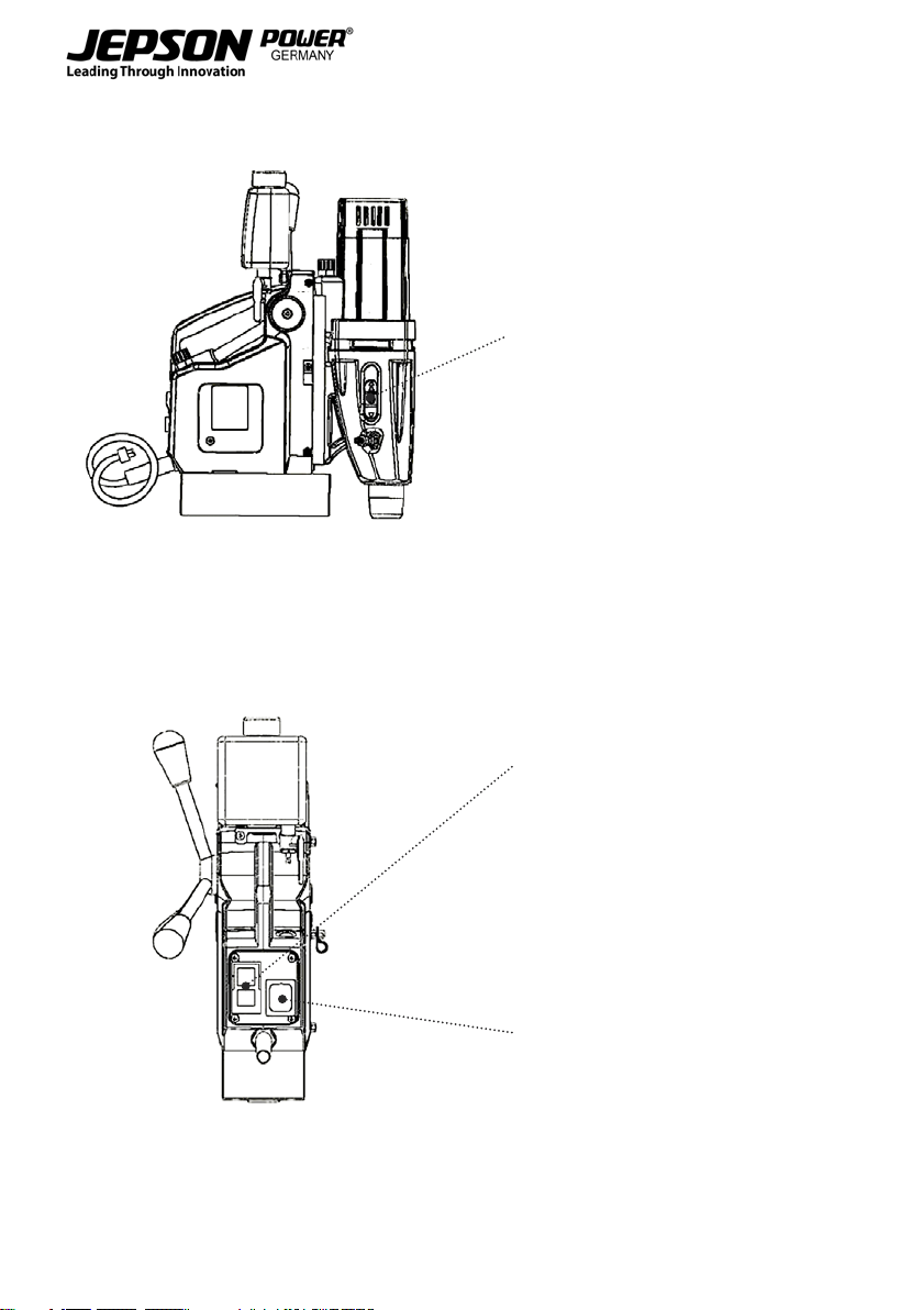
EN Speed selection
DE Geschwindigkeitsauswahl
FR Sélection de la vitesse
NL Snelheidsselectie
ES Selección de velocidad
PT Selecção da velocidade
IT Selezione della velocità
EN Motor switch
DE Motorschalter
FR Commutateur du moteur
NL Motorschakelaar
ES Interruptor del motor
PT Interruptor do motor
IT Interruttore motore
EN Magnet switch
DE Magnetschalter
FR Interrupteur magnétique
NL Magneetschakelaar
ES Interruptor magnético
PT Interruptor magnético
IT Interruttore del magnete
2

EN
DE
FR
NL
ES
PT
IT
EN 4
1. EC DECLARATION OF CONFORMITY 4
2. OPERATING INSTRUCTIONS 4
3. FOREWORD 5
4. TECHNICAL SPECIFICATION 5
5. SHORT DESCRIPTION 6
6. SCOPE OF DELIVERY 6
6.1. MAGPRO 40 2S 6
6.2. MAGPRO 80 4S 6
7. BEFORE USING THE MACHINE 6
8. SAFETY REGULATIONS 7
8.1. ADDITIONAL SAFETY PRECAUTIONS FOR THE MAGNETIC CORE DRILL MACHINE 8
8.2. POWER SUPPLY AND GROUNDING 9
9. STARTUP 9
9.1. ELECTRICAL SAFETY CHECKS 9
9.2. BEFORE STARTING WORK OR USE OF MAGNETIC CORE DRILL MACHINE 9
10. OPERATIONS 9
10.1. SPEED SELECTION OF MAGPRO 40 2S 9
10.2. SPEED SELECTION OF MAGPRO 80 4S 10
10.3. SWITCHING ON THE MAGNET 10
10.4. SWITCHING OFF THE MAGNET 10
10.5. CORE AND TWIST DRILLING WITH THE MACHINE 11
10.6. AFTER EVERY TOOL USAGE 11
11. MAINTENANCE 11
11.1. REPLACING THE CARBON BRUSHES 11
12. OPTIONAL ACCESSORIES 12
12.1. GENERAL ACCESSORIES 12
12.2. FOR THE MAGPRO 80 4S 12
13. QUOTATION 12
14. SPARE PARTS 12
15. WARRANTY 12
16. WEEE 13
TABLE OF CONTENTS
3

EN
1. EC DECLARATION OF CONFORMITY
(according to Appendix IIA of the machine Directive)
We, Jepson Power GmbH, Ernst – Abbe – Straße 5, 52249 Eschweiler, Germany, as the manufacturer
declare herewith under our responsibility that the product:
Name: Magnetic Core Drill Machine
Type: MagPro 40 2s | MagPro 80 4S
Manufacturing date: See machine label
Serial number: See machine label
complies with the following standards, directives and referenced standard documents:
2006/42/EC Machinery Directive
EN ISO 12100:2010
EN61029-1:2009 + A11:2010
EN61029-2-9:2012+A11:2013
EN61029-2-10:2010+A11:2013
Pierre Michiels, Managing Director
Name, Position Eschweiler, 01.08.2021
2. OPERATING INSTRUCTIONS
Please read this manual thoroughly before the machine is transported and before any operation.
Reproductions of any kind may be made only with our authorization. The manufacturer reserves the
right to make changes to the technical design of the development without notice. Changes for technical
advancement reserved.
FOR YOUR SAFETY!
Read the manual
Wear protective goggles
Wear ear protector
Wear mask
Wear safety shoes
Wear proper close-t work clothing
Do not wear protection gloves when machine is running or machine operation.
Wear protective gloves to prevent injuries from sharp metal swarfs or debris.
EN
4

EN
DE
FR
NL
ES
PT
IT
3. FOREWORD
A new MCD series of high-speed ecient magnetic core drilling machines
The magnetic core drill machine is the most commonly used machine employed in processing metal holes
coring and drilling as well as holes coring and drilling of other materials. The reason for this lies in the fact that
the magnetic core drill machine is very compact in construction, combined with the use of quality core drills
or twist drills and is very simple to operate. The Jepson line of magnetic core drill
machines provides ecient hole coring and drilling.
These machines are normally operated with HSS core drills or carbide-tipped core drills, the powerful motor
and proper cutting speeds eciently core holes or drill holes through metals, etc. In addition these magnetic
core drills only require some cooling lubricant. Cooling lubricant aids coring and drilling by reducing heat to
increase core drills or drill bits working eciency.
With the powerful motor and industrial grade gear sets, Jepson magnetic core drill machine oer quality and
durability. We wish you productive work with your Jepson product.
4. TECHNICAL SPECIFICATION
Machine MagPro 40 2S MagPro 80 4S
Voltage / Wattage 230V~ / 50Hz / 1100W 230V~ / 50Hz / 1600W
Voltage / Amp 115V~ / 9 A 115V~ / 14A
Speed 1 (idling) 650 min-1 190 min-1
Speed 2 (idling) 1100 min-1 300 min-1
Speed 3 (idling) - 420 min-1
Speed 4 (idling) - 660 min-1
Core Drill Type Weldon 19mm | 3/4” MK3 – 19mm | 3/4”
Cutting Depth 30mm / 55 mm 30mm / 55mm / 110mm
Max Core Drill Diameter 40mm | 1 9/16” 80mm | 3 1/8”
Max Twist Drill Diameter 13mm | 1/2” 16mm | 5/8”(32 MK3)
Stroke Length 165mm 270mm
Approximate Net Weight 13 kg 24 kg
EN
5
5. SHORT DESCRIPTION
The construction of MAGNETIC CORE DRILL
MACHINE is designed and built according to
current international standards of the machine tool
industry. The machines comply with the current
regulations for emissions and safety at work.
Please read the user instruction manual thoroughly,
particular the rules for the prevention of accidents.
Do not use tool other than the intended use as well
as cleaning and caring of the tool.
IMPORTANT
If changes to a machine are made
without authorization, null and void
and the EC conformity mark ceases to
be valid. The machine may no longer be operated.
Likewise, the guarantee and the liability of the
manufacturer are cancelled.
JEPSON Magpro 40 2s & Magpro 80 4s stand out
for:
• Easy transportation and compact
• Creating larger work space
• Simple operation
• Core drill holes through metal or none metal
materials
6. SCOPE OF DELIVERY
6.1. MAGPRO 40 2S
• Carry case
• Lashing strap
• Coolant tank
• Tools
• Chip protection
6.2. MAGPRO 80 4S
• Carry case
• Lashing strap
• Coolant tank
• Tools
• Chip protection
• Ejector wedge
• CM3 / Weldon 19 adapter
7. BEFORE USING THE MACHINE
BEFORE USING THE JEPSON
MAGNETIC CORE DRILL MACHINE
FOR THE VERY FIRST TIME, PLEASE
READ THE INSTRUCTION MANUAL.
Always check for any visible sign of damage before
use. Follow below safety regulations to prevent
accidents and injuries.
Warning: The magnetic cord drill
machine can only be operated when
the magnet is turned on. Make sure the
tool is securely magnetized and use the
safety lashing strap to tighten the tool. Make sure
tool will fall away from operator in a situation where
tool will loose magnetic holding power and safety
lashing is unable to hold the tool in a safe position.
Warning: The magnetic clamping power
depends on the work surface. The
substrate surface paint, and any surface
coating, and surface level of
smoothness aects the clamping power. If the work
surface is not metal, prepare a smooth level low
carbon steel plate at least 25 mm or 1 inch in
thickness and at least 100 mm by 200 mm in size to
ensure tool can be magnetized with good holding
power. If the work surface is a low thickness thin
metal, above mentioned metal plate must be added
under the work piece for the magnet to work
properly. The added metal plate must be secured to
prevent shifting or falling.
When coring or drilling none ferrite metals such as
aluminum or uneven surface such as corrugated
metals etc, there will be zero or minimal holding
power for the magnetic core drill machine. Special
holding device must be used else do not proceed
with any work to core or to drill.
Warning: When working above ground,
always wear safety harness to prevent
falling to prevent injuries from operator.
Always recheck tool is safely positioned
and tighten by lashing strap.
Attention: When starting the magnetic
core drill machine the oscillating
motion may cause sudden movement.
When there is power cut to the power
supply the oscillating motion may create sudden
movement. These sudden movements may create
unbalance to operator working above ground
creating danger to operator. Make sure the operator
is properly protected from falling wearing safety
harness.
EN
6

EN
DE
FR
NL
ES
PT
IT
Warning: Extreme caution for
connection of the magnetic core drill
machine to the power source. Make
sure the power source is properly
grounded. Check the power source has the same
voltage and frequency rating as the magnetic core
drill machine. Do not connect and use if there is any
dierences in voltage and frequency!
Attention: It is a good practice to pay
attention that the power cord is free
from any entanglement. Make sure the
cable is not in a path that is damp. Do
not use the tool if there is any visual sign of damage
to power cord. Only extension cable with 1.5mm² in
diameter can be used. Check to make sure the
extension cable has no visual damage.
Always verify the extension cable is approved for
use for the job site.
Warning: Do not operate the magnetic
core drill machine on the same surface
as the welding equipment set up.
Welding equipment can cause severe
damage to the magnetic block and electrical cord
that may lead to personal injuries to the operator.
Attention: When coring or drilling
through multiple layers, make sure the
core drill path is clear and free of swarfs
and debris. Second layer coring or
drilling may be more dicult. Do not press hard on
the handle and put too much force. Excessive force
applied does not speed up the coring or drilling
process. Can only bring more wear and tear to the
core drill or drill bit.
Warning: Do not turn on the machine if
the core drill or drill is touching the
work piece surface. Make sure there is
enough space before turning on the
machine. Always allow the machine to run at full
speed. If core drill or drill bit is touching the work
piece surface when machine is turned on, the
contact and start up force can twist and oscillate
suddenly. This may create injuries to operator.
Attention: When machine has reached
normal operating speed, begin coring
or drilling by following very slow feed
rate. Turn on the coolant or spray the
cutting surface. The initial contact of the core drill or
drill bit and work piece must be gentle. When
cutting or drilling mark is visible, begin to feed the
machine with gentle and even force. Let the core
drill or drill bit do the work. Do not force the
machine. Ease up pressure immediately after the
cutter or drill bit cut through.
Attention: Magpro 40 2s: When
inserting the core drill, loosen the two
Allen set screws. Appropriate 4mm
Allen wrench is provided. Make sure the
direct tool mount is clean and free of any debris or
foreign objects. Always insert the appropriate
ejector pin of the core drill. Make sure the core drill
has no physical damage. Tighten the two Allen set
screws to secure the core drill properly. Fill lubricant
tank and check the lubricant connections and
functions.
Attention: Magpro 80 4s: Always clean
the Weldon shank of the spindle and
the industrial tool holder taper. Insert
the industrial tool holder into the
tapered spindle. When inserting the core drill,
loosen the two Allen set screws. Appropriate 5mm
Allen wrench is provided. Make sure the direct tool
mount is clean and free of any debris or foreign
objects. Always insert the appropriate ejector pin of
the core drill. Make sure the core drill has no
physical damage. Tighten the two Allen set screws
to secure the core drill properly. Fill
lubricant tank and check the lubricant connections
and functions.
Attention: Turn o the machine
immediately after coring or drilling.
Before removing the tool or before
turning o the magnetic switch, make
sure to hold onto the handle of the machine with
one hand rmly, than turn o the magnet switch
and lift the machine o the work surface.
8. SAFETY REGULATIONS
1. Keep work area clear. Cluttered areas and
benches invite injuries.
2. Consider work area environment. Do not
expose tools to rain. Do not use tools in damp
or wet locations. Keep work area well lit. Do
not use tools in the presence of ammable
liquids or gases.
3. Guard against electric shock. Avoid body
contact with earthed and grounded surfaces
(e.g. pipes, radiators, ranges, refrigerators).
EN
7

4. Keep other persons away. Do not let persons,
especially children, not involved in the work,
touch the tool or the extension cord and keep
them away from the work area.
5. Store idle tools. When not in use, tools should
be stored in a dry locked-up place, out of
reach of children.
6. Do not force the tool. It will do the job better
and safer at the rate for which it was intended.
7. Use the right tool. Do not force small tools to
do the job of heavy duty tool. Do not use tools
for purposes not intended; for example do not
use circular saws to cut tree limbs or logs.
8. Dress properly. Do not wear loose clothing
or jewelry, which can be caught in moving
parts. Non-skid footwear is recommended
when working outdoors. Wear protective hair
covering to contain long hair.
9. Use protective equipment. Use safety glasses.
Use face or dust mask if working operations
create dust.
10. Connect dust extraction equipment. If the
tool is provided for the connection of dust
extraction and collecting equipment, ensure
these are connected and properly used.
11. Do not abuse the cord. Never yank the cord to
disconnect it from the socket. Keep the cord
away from heat, oil and sharp edges.
12. Secure work. Where possible use clamps or
a vice to hold the work. It is safer than using
your hand.
13. Do not overreach. Keep proper footing and
balance at all times.
14. Maintain tools with care. Keep cutting
tools sharp and clean for better and safer
performance. Follow instruction for lubricating
and changing accessories. Inspect tool
cords periodically and if damaged repair by
an authorized service facility only. Inspect
extension cords periodically and replace if
damaged. Keep handles dry, clean and free
from oil and grease.
15. Disconnect tools. When not in use, before
servicing and when changing accessories such
as blades, bits and cutters, disconnect tools
from the power supply.
16. Remove adjusting keys and wrenches. Form
the habit of checking to see that keys and
adjusting wrenches are removed from the tool
before turning it on.
17. Avoid unintentional starting. Ensure switch is
in“o”position when plugging in.
18. Use outdoor extension leads. When the tool
is used outdoors, use only extension cords
intended for outdoor use and so marked.
19. Stay alert. Watch what you are doing, use
common sense and do not operate the tool
when you are tired.
20. Check damaged parts. Before further use
of tool, it should be carefully checked to
determine that it will operate properly and
perform its intended function. Check for
alignment of moving parts, binding of moving
parts, breakage of parts, mounting and any
other conditions that may aect its operation.
A guard or other part that is damaged should
be properly repaired or replaced by an
authorized service centre unless otherwise
indicated in this instruction manual. Have
defective switches replaced by an authorized
service centre. Do not use the tool if the switch
does not turn it on and o.
21. Warning. The use of any accessory or
attachment other than one recommended in
this instruction manual may present a risk of
personal injury.
22. Have your tool repaired by a qualied
specialist. This electric tool complies with
the relevant safety rules. Repairs should only
be carried out by qualied specialist using
original spare parts otherwise this may result
in considerable danger to the user.
8.1. ADDITIONAL SAFETY PRECAUTIONS FOR
THE MAGNETIC CORE DRILL MACHINE
1. Always clamp the work piece securely with
safety lashing.
2. Observe the rotation direction of the core drill.
3. Ensure that the core drill is always sharp, is
unimpeded and runs without vibration.
4. Lift the magnetic core drill o the work piece
before the on-o switch is operated.
5. Before drilling, allow the motor to achieve full
speed.
6. Operate the machine only if it is properly
grounded.
7. Do not reach into the workspace of operating
machine with your hands while the electric
power cord is connected to the socket.
8. Protect the machine against moisture.
9. Wear safety goggles, protective gloves, ear
protector and mask. Do not wear protective
gloves when the core drill machine is running.
EN
8

EN
DE
FR
NL
ES
PT
IT
Gloves can be caught by the core drill machine
create serious injuries to hands.
10. The device may not be operated in a damp
environment
8.2. POWER SUPPLY AND GROUNDING
In the case of malfunction or a defect, the
grounding provides a path of lowest resistance
for the electric current in order to reduce the
risk of electric shock. The machine is equipped
with a power cable provided with an equipment
protective conductor and a grounded plug.
The plug must be plugged into a
suitable socket that is properly installed
and grounded according to all local
laws and regulations. Do not alter the
provided plug. If it does not t into the socket, an
electrician must install a suitable socket.
9. STARTUP
After unpacking the machine from the packaging,
verify if there is any visual damage. Place the
machine on a low carbon metal surface so that
it is solid and level. A minimal thickness of 25 mm
or 1 inch and at least 100 mm by 120 mm low
carbon steel is required for magnets to function
properly with sucient holding force. Check for tool
magnetic clamping function. Secure the machine
with safety latching strap. Strap provides additional
tool holding security if magnet loosened or power
fails. Check that the tool is tightened securely before
operating tool. When additional low carbon steel
plate is used, make sure the steel is also secured
properly.
9.1. ELECTRICAL SAFETY CHECKS
Before inserting the power supply plug into the
socket of power source, make sure that it is a
grounded socket. Make sure the power source
voltage and frequency match the magnetic core
drill machine. In the case cable extensions are
used, operator must make sure that they are
also grounded. Only use extension cables with a
cable cross-section of 1.5mm². Only use approved
extension cables for the work place.
9.2. BEFORE STARTING WORK OR USE OF
MAGNETIC CORE DRILL MACHINE
Plug in tool by observing the electrical safety checks
described above. Turn on the magnet and check the
function of the magnetic holding power. Magnetic
core drill machine cannot be turn on unless the
magnet power is turned on rst. This is a safety
feature and does not guarantee the magnet is set
up properly. Always check the magnet holding
power and proper tightening of the magnetic tool
before turning on the magnetic core drill machine.
Spindle Check:
Before inserting core drill or drill bits make sure the
machine spindle, tool holder, and the Weldon shank
are free of debris and any foreign objects. Before
use, the tool is not damaged nor worn out, and also
free of debris and any foreign objects. Damaged and
worn out tool may cause unexpected movement of
the magnetic core drill machine leading to danger
to operator and damage to machine. Good quality
core drill will ensure ecient work and safety.
Note:
Always use the appropriate ejector pin of the core
drill tool. Make sure the machine is turned o before
installing or removing the core drills. Tighten the
two Allen screws properly before starting. Adjust
the speed of the machine when the machine is o
and at stand still. Desired speeds selection, follow
the label on the motor housing of the machine.
Attention: Machine can only be turned
on when the magnetic clamp is
working. Will turn o when magnetic
clamp power is cut o. Allow the
overheated tool to cool o running at idle for a few
minutes.
10. OPERATIONS
Recheck the magnetic core drill machine is correctly
plugged in and connected to the correct power
source. Recheck to make sure the magnetic core
drill machine and the work piece is clamped
securely. Recheck to make sure the operator has
appropriate safety equipment if the work is above
ground. Recheck to prevent any injuries from
electrical shock and operating injuries from tool or
operator fallen o.
10.1. SPEED SELECTION OF MAGPRO 40 2S
With the tool properly set up. The speed selector
is at left side of gear box. The upper position is the
high speed. And the lower position is the low speed.
Adjust the speed only when tool is not turned on
and not rotating. Refer to the technical data section
of the manual for the rpm of both high and low
EN
9

speed. Select the coring or drilling speed according
to the material and core drill or drill bit diameter.
Proper speed yields most ecient work.
10.2. SPEED SELECTION OF MAGPRO 80 4S
With the tool properly set up. The speed selectors
are at left side and right side of gear box. There are
four stages or four speeds.
Lowest speed or stage 1:
The left hand selector adjusts to the down position
and the right hand selector adjusts to the up
position. This set up yields the lowest speed. Adjust
the speed only when tool is not turned on and not
rotating. Refer to the technical data section of the
manual for the rpm of both high and low speed.
Select the coring or drilling speed according to the
material and core drill or drill bit diameter.
Proper speed yields most ecient work.
Second speed or stage 2:
The left hand selector adjusts to the down position
and the right hand selector adjusts to the down
position. This set up yields the second lowest speed.
Adjust the speed only when tool is not turned on
and not rotating. Refer to the technical data section
of the manual for the rpm of both high and low
speed. Select the coring or drilling speed according
to the material and core drill or drill bit diameter.
Proper speed yields most ecient work.
Third speed or stage 3:
The left hand selector adjusts to the up position and
the right hand selector adjusts to the up position.
This set up yields the third speed. Adjust the speed
only when tool is not turned on and not rotating.
Refer to the technical data section of the manual
for the rpm of both high and low speed. Select the
coring or drilling speed according to the material
and core drill or drill bit diameter. Proper speed
yields most ecient work.
Highest speed or stage 4:
The left hand selector adjusts to the up position
and the right hand selector adjusts to the down
position. This set up yields the fourth or highest
speed. Adjust the speed only when tool is not
turned on and not rotating. Refer to the technical
data section of the manual for the rpm of both high
and low speed. Select the coring or drilling speed
according to the material and core drill or drill bit
diameter. Proper speed yields most ecient work.
Attention: Switch or selecting the
speeds of the magnetic core drill
machine must be done when the tool
motor is turned o and tool at rest not
rotating. Use one hand to rotate spindle if necessary
to get the selector to set in gear properly.
10.3. SWITCHING ON THE MAGNET
When the core drill machine is properly set up and
secured. Operator may turn on the magnet. The
magnetic holding force is available if and only if the
work surface or magnetic steel surface is not too
thin. Follow the safety recommendation of Section
8 of Start-Up. Strongest clamping power of the
magnet is available after the tool motor is turned
on. The magnetic power switch will light up when
powered on. If the light is not turned on check
the switch and replace damaged switch before
continuing work.
10.4. SWITCHING OFF THE MAGNET
With the magnetic core drill machine turned o,
tool must be at stationary position or not rotating
before the magnetic switch can be turned o.
Make sure the Magnetic core drill machine is still
properly tightened and secure before turning o
the magnetic switch. Hold onto the machine handle
tightly with one hand than turn o the magnet
switch. Always take extra precaution to prevent tool
and operator from falling.
Attention: After coring or drilling run
the tool without load for at least a
minute or when tool has become
cooler. Never overload the tool during
coring or drilling. Over heating can damage the
motor. Prevent the magnet from overheating. When
coring or drilling work is complete, do not leave the
magnetic core drill machine with the magnet power
turned on. When coring or drilling work is complete
always turn o the tool and remove as soon as
possible.
With the magnetic switch turned on and recheck
holding power of magnet and tool set up before
turning on the motor of the tool. The green button
of the motor on/o switch when pushed will start
the motor. The red button of the motor on/o
switch when pushed will stop the motor. The motor
on/o switch can be used when the magnet switch
is turned on. The motor on/o switch cannot work
when the magnet switch is turned o.
EN
10
EN
DE
FR
NL
ES
PT
IT
Attention: The tool motor switch will
shut o automatically when there is cut
to the power source. Do not turn on
tool until the power source is veried by
certied electrician to be in good working
condition. Do not use tool if the magnet has failed
or damaged.
10.5. CORE AND TWIST DRILLING WITH THE
MACHINE
Always insert the appropriate ejector pin suitable
for the core drill to be used. Align the magnetic
core drill and secure with latching strap when
necessary. Switch on the magnet. Recheck electrical
connection and tightening of tool before turning
on the motor to begin coring or drilling. Use the
handle to direct the core drill or drill. Never force the
tool. Always use quality cutting oil for cooling and
lubricating.
Coring and drilling do not require great force. Use
of quality cutting oil and quality core drills aids
in work eciency. When working on horizontal
or over head position, the cutting oil cannot ow
automatically. Always spay the inside of the core
drill and constantly spray cutting oil to aid the tool
to achieve coring or drilling eciency in none ideal
positions.
Attention: Never force the tool. Forcing
the tool to core or drill does not yield
faster work. Forcing the tool only create
more wear and tear to the core drill,
drill, and tool. Never use damaged core drill and
drill. Always inspect and replace core drill and drill
whenever necessary.
Warning: Forcing the tool can damage
the core drill or drill. There is danger of
cut injuries by when core drill and drill
bit is damaged.
When tool coring and drilling blockage is caused
by broken core drill or drill, turn the machine o
immediately. Unplug the tool before proceeding to
replace the broken core drill or drill. Use the handle
to move the machine to an upper position before
proceeding to replace the broken core drill or
drill. Remove any swarfs or debris. Wear protective
gloves when necessary to prevent any injuries from
sever cuts to hands. Never wear protective gloves to
operate the tool.
When tool coring and drilling blockage are caused
by excessive swarfs or debris, turn o the motor
and make sure the magnet is not turned o. Make
sure the machine continue to hold the tool before
proceeding to remove excess swarfs or debris.
Clean the hole and lubricate the hole prior to
continue coring or drilling. Always recheck the tool
for the magnetic holding function and lashing are
functioning properly before continue any work.
10.6. AFTER EVERY TOOL USAGE
Remove the core drill or drill from machine. Remove
any swarfs or debris. Clean tool from any coolant
and visually inspect for any sign of damage. Always
clean tool holder of the machine. Clean the guide
of the magnetic core drill slide. At the same time
inspect the function of the slide guide. If tool has a
lot of clearance space or become loose, tool must be
adjusted. Loosen the clamping nut and tighten the
clamping bolt evenly. Retighten the clamping nut
to secure the adjustments in place. After cleaning
and inspecting the machine, always put tool back
into the carrying case as well as the securing lashing
and core drill or drill used.
11. MAINTENANCE
11.1. REPLACING THE CARBON BRUSHES
1. Replace the carbon a brush when they are
worn down to approx. 1/4“ (6 mm) or spark
formation occurs. Both brushes must be
replaced at the same time.
2. Remove the worn brushes, insert the new
brushes and close the cover again.
3. Carbon brushes replacement can be
performed by authorized service stations and
or shops. Only original parts can be used. Any
unauthorized parts used as replacements void
the warranty and manufactures liability for
damages and injuries.
EN
11

12. OPTIONAL ACCESSORIES
12.1. GENERAL ACCESSORIES
• HSS-Co core drills 30 mm Ø 12 - 130 mm
(490212 - 4902130)
• HSS-Co core drills 55 mm Ø 12 - 130 mm
(490512 - 4905130)
• „Goldnger“ : TiN coated HSS-Co
core drills 30 mm Ø 12 - 60 mm
(490212TiN - 4902130TiN)
• HSS-Co core drill set 30 mm Ø 12, 14, 16, 18,
20, 22 + pilot pin (490145)
• Carbide tipped core drill set 30 mm Ø 1x12,
1x 14, 1x16, 1x18, 1x20, 1x22 mm + pilot pin
(490148)
• „Goldnger“ core drill set TiN-coated 30 mm Ø
12, 14, 16, 18, 20, 22 + pilot pin (490145TiN)
• Drill chuck and adapter 13 mm (490152A)
• Weldon adapter 19 mm for Fein core drills with
quick-in shank and + pilot pin / centering pin
(490154)
• Magnetic chip collector (490153)
• High-performance drilling and cutting oil
spray for optimal cooling and higher cutting
performance - Content: 400 ml (490020)
12.2. FOR THE MAGPRO 80 4S
• Drill chuck 16 mm + MK3 adapter (490164)
• Weldon 32 CM3 adapter for core drills from Ø
61 mm (490163)
13. QUOTATION
When returning a defective machine for repair with
cost estimate. We charge a handling fee of 50€, but
does not apply if a repair order or purchase of a new
machine is given.
14. SPARE PARTS
For current spare parts list with order numbers
please visit our website:
www.drycutter.com
15. WARRANTY
The warranty time (warranty according to the
commercial code) is 12 months from the day of sale
to the end consumer. It covers and is limited to the
free replacement of the defective parts or the free
repair of defects that are demonstrably due to the
use of imperfect materials during production or due
to assembly errors. Incorrect use or start-up and
unauthorized installations or repairs not specied
in the operating instructions void the warranty.
Parts that are subject to wear are also excluded
from the warranty. We expressly reserve the right
to make decisions on the warranty application. The
warranty is void if the device is opened by a third
party. Transport damages, maintenance work as
well as damage and malfunctions due to insucient
maintenance are not covered by the warranty.
For warranty claims, the proof of purchase of the
device must be given by presenting the delivery
note, bill, or cash receipt. As far as it is legal, we
assume no liability for any personal, material or
consequential damages, in particular if the device
is used dierently than for the purpose indicated in
the operating instructions, not installed or repaired
according to the operating instructions, or repairs
were executed by a layperson. We reserve the right
to perform repairs or maintenance over and above
the ones specied in these operating instructions at
the factory.
Exclusion of the JEPSON POWER warranty
The warranty also excludes:
• Wear parts such as: Switches, carbon brushes,
magnets, and Cutting tools (core drills, drills,
etc.).
• Parts that are subject to wear through use or
natural wear and tear, as well as tool defects
due to wear and tear due to normal conditions
of use or due to natural wear and tear.
• Tool failure due to non-compliance with the
instruction manual, unconventional use,
abnormal atmospheric conditions, improper
operating conditions, overload, or lack of
service or maintenance.
• Tool failure due to replacement parts or
additional parts that are not genuine Jepson
Power parts.
• Machines to which changes or additions have
been made.
• The minor dierences from the intended use
of the device that are not material to the value
and suitability of the tool.
In the following cases, a guarantee claim for
damage to the magnetic base on the magnetic
drilling machines of our MagPro series is excluded:
1. Abnormal abrasion of the magnet surface due
to permanent movement of the machine on
metallic surfaces without lifting the device.
EN
12

EN
DE
FR
NL
ES
PT
IT
2. Simultaneous earth connection (earthing)
of welding devices on the workpiece and
commissioning of the magnetic drill leads to a
short circuit and can permanently damage the
magnetic base.
The quality and safety of the JEPSON magnetic
core drill machine depends on the exclusive use
of original JEPSON core drills. Quality core drills
provide ecient work. The use of other core drills
may damage the machines.
16. WEEE
1. Do not dispose of electrical appliances as
unsorted municipal waste, use separate
collection facilities.
2. Contact your local government for information
regarding the collection systems available.
3. If electrical appliances are disposed of in
landlls or dumps, hazardous substances
can leak into the groundwater and get into
the food chain, damaging your health and
well-being.
4. When replacing old appliances with new ones,
the retailer is legally obligated to take back
your old appliance for disposal at least for free
of charge.
Jepson Power GmbH
Ernst-Abbe-Str. 5
52249 Eschweiler, Germany
Tel: +49 (0) 2403 64 55 0
Fax: +49 (0) 2403 64 55 15
www.drycutter.com
INHALTSVERZEICHNIS
13

INHALTSVERZEICHNIS
14

EN
DE
FR
NL
ES
PT
IT
DE 16
1. EGKONFORMITÄTSERKLÄRUNG 16
2. BEDIENUNGSANLEITUNG 16
3. VORWORT 17
4. TECHNISCHE DATEN 17
5. KURZBESCHREIBUNG 18
6. LIEFERUMFANG 18
6.1. MAGPRO 40 2S 18
6.2. MAGPRO 80 4S 18
7. VOR DER ERSTEN NUTZUNG 18
8. SICHERHEITSVORSCHRIFTEN 20
8.1. ZUSÄTZLICHE SICHERHEITSVORKEHRUNGEN FÜR DIE MAGNETKERNBOHRMASCHINE 21
8.2. STROMVERSORGUNG UND ERDUNG 21
9. INBETRIEBNAHME 21
9.1. ELEKTRISCHE SICHERHEITSÜBERPRÜFUNGEN 22
9.2. VOR BEGINN DER ARBEITEN ODER VERWENDUNG DER MAGNETKERNBOHRMASCHINE 22
10. BETRIEB 22
10.1. GESCHWINDIGKEITSAUSWAHL DES MODELLS MAGPRO 40 2S 22
10.2. GESCHWINDIGKEITSAUSWAHL DES MODELLS MAGPRO 80 4S 23
10.3. EINSCHALTEN DES MAGNETEN 23
10.4. AUSSCHALTEN DES MAGNETEN 23
10.5. ENTKERNEN UND BOHREN MIT DER MASCHINE 24
10.6. NACH JEDEM WERKZEUGEINSATZ 25
11. WARTUNG 25
11.1. AUSTAUSCH DER KOHLEBÜRSTEN 25
12. OPTIONALES ZUBEHÖR 25
12.1. ALLGEMEINES ZUBEHÖR 25
12.2. FÜR DIE MAGPRO 80 4S 25
13. KOSTENVORANSCHLAG 25
14. ERSATZTEILE 25
15. GARANTIE 25
16. WEEE 26
15
INHALTSVERZEICHNIS

DE
1. EGKONFORMITÄTSERKLÄRUNG
(nach Anhang IIA der Maschinenrichtlinie)
Wir, Jepson Power GmbH, Ernst – Abbe – Straße 5, 52249 Eschweiler, Germany, erklären in alleiniger
Verantwortung , dass das Produkt
Maschinenbezeichnung: Magnetkernbohrmaschine
Typ: MagPro 40 2s | MagPro 80 4S
Baujahr: Siehe Maschinenetikett
Seriennummer: Siehe Maschinenetikett
Auf das sich diese Erklärung bezieht, mit den folgenden EG-Richtlinien und harmonisierten Normen oder
anderen normativen Dokumenten übereinstimmt:
2006/42/EC Machinery Directive
EN ISO 12100:2010
EN61029-1:2009 + A11:2010
EN61029-2-9:2012+A11:2013
EN61029-2-10:2010+A11:2013
Pierre Michiels, Managing Director
Name, Position Eschweiler, 01.08.2021
2. BEDIENUNGSANLEITUNG
Bitte lesen Sie dieses Handbuch sorgfältig durch, bevor Sie die Maschine transportieren und in Betrieb
nehmen
Vervielfältigungen jeglicher Art dürfen nur mit unserer Genehmigung vorgenommen werden. Der Hersteller
behält sich das Recht vor, Änderungen an der technischen Ausführung der Entwicklung ohne Vorankün-
digung vorzunehmen. Änderungen für technische Verbesserungen vorbehalten.
ZU IHRER SICHERHEIT!
Lesen Sie das Handbuch sorgfältig durch
Tragen Sie eine Schutzbrille
Trage Sie Gehörschutz
Tragen Sie eine Schutzmaske
Tragen Sie Sicherheitsschuhe
Tragen Sie angemessene, eng anliegende Arbeitskleidung
Tragen Sie keine Schutzhandschuhe, wenn die Maschine läuft oder die Maschine in Betrieb ist.
Tragen Sie Schutzhandschuhe, um Verletzungen durch scharfe Metallspäne oder Ablagerungen zu
vermeiden.
16
DE

EN
DE
FR
NL
ES
PT
IT
3. VORWORT
Eine neue MCD-Serie von ezienten Hochgeschwindigkeits-Magnetkernbohrmaschinen
Die Magnetkernbohrmaschine ist die am häugsten eingesetzte Maschine für die Bearbeitung von
Metall-Kernbohrungen und Bohrungen sowie von Kernbohrungen und Bohrungen anderer Materialien. Der
Grund dafür liegt in der Tatsache, dass die Magnetkernbohrmaschine sehr kompakt gebaut ist, kombiniert
mit dem Einsatz von hochwertigen Kernbohrern oder Spiralbohrern und sehr einfach zu bedienen ist. Die
Jepson-Linie der Magnetkernbohrmaschinen ermöglicht ein ezientes Kernbohren und Bohren.
Diese Maschinen werden normalerweise mit HSS-Kernbohrern oder hartmetallbestückten Kernbohrern
betrieben. Der leistungsstarke Motor und die richtigen Schnittgeschwindigkeiten ermöglichen ein ezientes
Kernbohren oder Bohren durch Metalle usw. Darüber hinaus benötigen diese Magnetkernbohrer nur etwas
Kühlschmiersto. Der Kühlschmiersto unterstützt das Entkernen und Bohren durch Reduzierung der Wärme,
um die Arbeitsezienz von Kernbohrern oder Bohrern zu erhöhen.
Mit den leistungsstarken Motor- und Industriegetrieben bietet die Magnetkernbohrmaschine von Jepson
Qualität und Langlebigkeit. Wir wünschen Ihnen eine produktive Arbeit mit Ihrem Jepson-Produkt.
4. TECHNISCHE DATEN
Maschine MagPro 40 2S MagPro 80 4S
Spannung / Leistung 230V~ / 50Hz / 1100W 230V~ / 50Hz / 1600W
Spannung / Ampere 115V~ / 9 A 115V~ / 14A
Geschwindigkeit 1(Leerlauf) 650 min-1 190 min-1
Geschwindigkeit 2 (Leerlauf) 1100 min-1 300 min-1
Geschwindigkeit 3 (Leerlauf) - 420 min-1
Geschwindigkeit 4 (Leerlauf) - 660 min-1
Kernbohrertyp Weldon 19mm | 3/4” MK3 – 19mm | 3/4”
Schnitttiefe 30mm / 55 mm 30mm / 55mm / 110mm
Max. Kernbohrdurchmesser 40mm | 1 9/16” 80mm | 3 1/8”
Max. Spiralbohrerdurchmesser 13mm | 1/2” 16mm | 5/8” (32 MK3)
Hublänge 165mm 270mm
Ungefähres Nettogewicht 13 kg 24 kg
17
DE
5. KURZBESCHREIBUNG
Die Konstruktion der MAGNETKERNBOHRMASCHINE
ist nach den aktuellen internationalen Normen
der Werkzeugmaschinenindustrie konzipiert und
gebaut. Die Maschinen entsprechen den geltenden
Vorschriften für Emissionen und Arbeitssicherheit.
Bitte lesen Sie die Bedienungsanleitung
sorgfältig durch, insbesondere die Unfallver-
hütungsvorschriften. Verwenden Sie das Werkzeug
nur für den bestimmungsgemäßen Gebrauch und
beachten Sie die Reinigungs- und Pegehinweise.
WICHTIG
Werden ohne Genehmigung
Änderungen an einer Maschine
vorgenommen, so erlischt die Gültigkeit
des EG-Konformitätszeichens. Die Maschine darf
nicht mehr betrieben werden. Ebenso erlischt die
Garantie und die Haftung des Herstellers.
JEPSON Magpro 40 2s & Magpro 80 4s zeichnen
sich aus durch:
• Einfacher Transport und Kompaktheit
• Schat größere Arbeitsäche
• Einfache Bedienung
• Kernbohrungen durch Metall oder nichtmetal-
lische Materialien
6. LIEFERUMFANG
6.1. MAGPRO 40 2S
• Transportkoer
• Zurrgurt
• Kühlmitteltank
• Werkzeuge
• Späneschutz
6.2. MAGPRO 80 4S
• Transportkoer
• Zurrgurt
• Kühlmitteltank
• Werkzeuge
• Späneschutz
• Auswerferkeil
• MK3 / Weldon 19 Adapter
7. VOR DER ERSTEN NUTZUNG
BEVOR SIE DIE JEPSON MAGNETKER-
NBOHRMASCHINE ZUM ERSTEN MAL
BENUTZEN, LESEN SIE BITTE DIE
BEDIENUNGSANLEITUNG.
Überprüfen Sie vor dem Gebrauch immer, ob
sichtbare Schäden vorliegen. Befolgen Sie die
folgenden Sicherheitsvorschriften, um Unfälle und
Verletzungen zu vermeiden.
Warnung: Die Magnetkernbohr-
maschine kann nur bei eingeschaltetem
Magneten betrieben werden.
Vergewissern Sie sich, dass das
Werkzeug sicher magnetisiert ist, und verwenden
Sie den Sicherheitszurrgurt, um das Werkzeug
festzuziehen. Stellen Sie sicher, dass das Werkzeug
vom Bediener wegfällt, wenn das Werkzeug die
magnetische Haltekraft verliert und die Sicherhe-
itsverzurrung das Werkzeug nicht in einer sicheren
Position halten kann.
Warnung: Die Magnetspannkraft ist
abhängig von der Arbeitsäche. Die
Untergrundfarbe und jede Oberächen-
beschichtung sowie der Oberächen-
glättegrad beeinussen die Klemmkraft. Wenn die
Arbeitsäche nicht aus Metall besteht, bereiten Sie
eine glatte, kohlenstoarme Stahlplatte mit einer
Dicke von mindestens 25 mm oder 1 Zoll und einer
Größe von mindestens 100 mm x 200 mm vor, um
sicherzustellen, dass das Werkzeug mit guter
Haltekraft magnetisiert werden kann. Wenn die
Arbeitsäche aus einem dünnen Metall besteht,
muss die oben genannte Metallplatte unter dem
Werkstück angebracht werden, damit der Magnet
ordnungsgemäß funktioniert. Die beigefügte
Metallplatte muss gegen Verrutschen oder Herunt-
erfallen gesichert sein.
Wenn Nicht-Ferritmetalle wie Aluminium oder
unebene Oberächen wie Wellblech usw. entkernt
oder gebohrt werden, gibt es keine oder nur
minimale Haltekraft für die Magnetkernbohr-
maschine. Es muss eine spezielle Haltevorrichtung
verwendet werden, da sonst keine Kern- oder
Bohrarbeiten durchgeführt werden dürfen.
Warnung: Tragen Sie bei Arbeiten über
dem Boden immer einen Sicherhe-
itsgurt, um ein Herunterfallen zu
verhindern und Verletzungen des
18
DE

EN
DE
FR
NL
ES
PT
IT
Bedieners zu vermeiden. Überprüfen Sie immer, ob
das Werkzeug sicher positioniert ist und ziehen Sie
es mit einem Zurrgurt fest.
Achtung: Beim Starten der Magnetkern-
bohrmaschine kann die oszillierende
Schwingung zu plötzlichen
Bewegungen führen. Bei Ausfall der
Stromversorgung kann die oszillierende
Schwingung zu plötzlichen Bewegungen führen.
Diese plötzlichen Bewegungen können zu Unwucht
beim Arbeiten über dem Boden führen und eine
Gefahr für den Bediener darstellen. Vergewissern Sie
sich, dass der Bediener mit einem Sicherheitsgurt
gegen Absturz gesichert ist.
Warnung: Extreme Vorsicht beim
Anschluss der Magnetkernbohr-
maschine an die Stromquelle.
Vergewissern Sie sich, dass die
Stromquelle ordnungsgemäß geerdet ist.
Überprüfen Sie, ob die Stromquelle die gleiche
Spannungs- und Frequenzbelastbarkeit wie die
Magnetkernbohrmaschine aufweist. Nicht
anschließen und verwenden, wenn es Unterschiede
in Spannung und Frequenz gibt!
Achtung: Es ist eine gute
Vorgehensweise, darauf zu achten, dass
das Netzkabel frei von Verschlingungen
ist. Achten Sie darauf, dass sich das
Kabel nicht in einem feuchten Bereich bendet.
Verwenden Sie das Gerät nicht, wenn sichtbare
Anzeichen einer Beschädigung des Netzkabels
vorliegen. Es können nur Verlängerungskabel mit
einem Durchmesser von 1,5 mm² verwendet
werden. Vergewissern Sie sich, dass das
Verlängerungskabel keine optischen Schäden
aufweist.
Überprüfen Sie immer, ob das Verlängerungskabel
für die Verwendung auf der Baustelle zugelassen ist.
Warnung: Die Magnetkernbohr-
maschine nicht auf der gleichen
Oberäche wie die eingerichtete
Schweißanlage betreiben.
Schweißgeräte können schwere Schäden am
Magnetblock und am Stromkabel verursachen, die
zu Verletzungen des Bedieners führen können.
Achtung: - Beim Bohren oder
Durchbohren mehrere Schichten ist
darauf zu achten, dass der Kernbohrpfad frei von
Spänen und Ablagerungen ist. Das Bohren oder
Entkernen der zweiten Schicht kann schwieriger
sein. Drücken Sie nicht zu fest auf den Gri und
üben Sie nicht zu viel Kraft aus. Eine übermäßige
Kraft beschleunigt den Kern- oder Bohrprozess
nicht. Es entsteht nur mehr Verschleiß am
Kernbohrer oder Bohrer.
Warnung: - Schalten Sie die Maschine
nicht ein, wenn der Kernbohrer oder der
Bohrer die Werkstückoberäche
berührt. Achten Sie darauf, dass
genügend Platz vorhanden ist, bevor Sie die
Maschine einschalten. Lassen Sie die Maschine
immer mit voller Geschwindigkeit laufen. Wenn der
Kernbohrer oder der Bohrer beim Einschalten der
Maschine die Werkstückoberäche berührt, kann
sich die Kontakt- und Anfahrkraft verdrehen und
plötzlich schwingen. Dies kann zu Verletzungen des
Bedieners führen.
Achtung: - Wenn die Maschine die
normale Arbeitsgeschwindigkeit
erreicht hat, beginnen Sie mit dem
Entkernen oder Bohren, indem Sie der
sehr langsamen Vorschubgeschwindigkeit folgen.
Schalten Sie das Kühlmittel ein oder sprühen Sie die
Schneidäche ein. Der erste Kontakt von
Kernbohrer oder Bohrer und Werkstück muss
schonend sein. Wenn die Schnitt- oder Bohrspur
sichtbar ist, beginnen Sie, die Maschine mit sanfter
und gleichmäßiger Kraft zu beschicken. Lassen Sie
den Kernbohrer oder den Bohrer die Arbeit
verrichten. Die Maschine darf nicht gewaltsam
betrieben werden. Entlasten Sie den Druck
unmittelbar nach der Durchbohrung.
Achtung: - Magpro 40 2s: Lösen Sie
beim Einsetzen des Kernbohrers die
beiden Inbusschrauben. Ein passender
4 mm Inbusschlüssel wird mitgeliefert.
Stellen Sie sicher, dass die direkte Werkzeughal-
terung sauber und frei von Fremdkörpern ist.
Stecken Sie immer den passenden Auswerferstift
der Kernbohrmaschine ein. Stellen Sie sicher, dass
die Kernbohrmaschine keine physischen Schäden
aufweist. Ziehen Sie die beiden Inbusschrauben an,
um den Kernbohrer richtig zu befestigen. Füllen Sie
den Schmierstotank und überprüfen Sie die
Schmierstoanschlüsse und -funktionen.
19
DE

Achtung: - Magpro 80 4s: Reinigen Sie
immer den Weldonschaft der Spindel
und den Konus des Industriewerkzeu-
ghalters. Setzen Sie den Industriew-
erkzeughalter in die konische Spindel ein. Lösen Sie
beim Einsetzen des Kernbohrers die beiden
Inbusschrauben. Ein passender 5 mm Inbusschlüssel
wird mitgeliefert. Stellen Sie sicher, dass die direkte
Werkzeughalterung sauber und frei von
Fremdkörpern ist. Stecken Sie immer den
passenden Auswerferstift der Kernbohrmaschine
ein. Stellen Sie sicher, dass die Kernbohrmaschine
keine physischen Schäden aufweist. Ziehen Sie die
beiden Inbusschrauben an, um den Kernbohrer
richtig zu befestigen. Füllen Sie den Schmierst-
otank und überprüfen Sie die Schmierstoan-
schlüsse und -funktionen.
Achtung: - Schalten Sie die Maschine
sofort nach dem Entkernen oder Bohren
aus. Bevor Sie das Werkzeug entfernen
oder den Magnetschalter ausschalten,
halten Sie den Gri der Maschine mit einer Hand
fest, schalten Sie den Magnetschalter aus und
heben Sie die Maschine von der Arbeitsäche ab.
8. SICHERHEITSVORSCHRIFTEN
1. Halten Sie den Arbeitsbereich sauber. Unüber-
sichtliche Bereiche und Arbeitstische laden zu
Verletzungen ein.
2. Berücksichtigen Sie die Umgebung des Arbeit-
sbereichs. Setzen Sie die Werkzeuge keinem
Regen aus. Verwenden Sie keine Werkzeuge
an feuchten oder nassen Orten. Halten Sie den
Arbeitsbereich gut beleuchtet. Verwenden Sie
keine Werkzeuge in der Nähe von brennbaren
Flüssigkeiten oder Gasen.
3. Vor Stromschlag schützen. Vermeiden
Sie Körperkontakt mit geerdeten und
erdgebundenen Oberächen (z.B. Rohre,
Heizkörper, Herden, Kühlschränke).
4. Halten Sie andere Personen fern. Lassen
Sie nicht zu, dass Personen, insbesondere
Kinder, die nicht an der Arbeit beteiligt sind,
das Werkzeug oder das Verlängerungskabel
berühren und halten Sie diese vom Arbeits-
bereich fern.
5. Lagern Sie ungenutzte Werkzeuge. Bei
Nichtgebrauch sollten die Werkzeuge an
einem trockenen, verschlossenen Ort und
außerhalb der Reichweite von Kindern
gelagert werden.
6. Das Werkzeug nicht mit Gewalt bearbeiten. Es
erledigt die Arbeit besser und sicherer in dem
Tempo, für das es bestimmt war.
7. Benutzen Sie das richtige Werkzeug.
Benutzen Sie keine kleinen Werkzeuge, um
schwere Arbeiten zu erledigen. Verwenden
Sie Werkzeuge nicht für nicht vorgesehene
Zwecke, z.B. keine Kreissägen zum Schneiden
von Baumstämmen oder Stämmen.
8. Ziehen Sie sich entsprechend an. Tragen
Sie keine lose Kleidung oder Schmuck, die
sich in beweglichen Teilen verfangen kann.
Bei Arbeiten im Freien wird rutschfestes
Schuhwerk empfohlen. Tragen Sie eine
schützende Haarbedeckung bei langem Haar.
9. Verwenden Sie Schutzausrüstung. Verwenden
Sie Schutzbrillen. Verwenden Sie Gesichts-
oder Staubmaske, wenn bei der Arbeit Staub
entsteht.
10. Schließen Sie die Staubabsaugung an.
Wenn das Werkzeug für den Anschluss von
Staubabsaug- und Auangvorrichtungen
vorgesehen ist, stellen Sie sicher, dass
diese angeschlossen und ordnungsgemäß
verwendet werden.
11. Missbrauchen Sie das Kabel nicht. Ziehen Sie
niemals das Kabel, um es von der Steckdose
zu trennen. Halten Sie das Kabel von Hitze, Öl
und scharfen Kanten fern.
12. Sichere Arbeit. Verwenden Sie nach
Möglichkeit Klemmen oder einen
Schraubstock, um das Werkstück zu halten. Es
ist sicherer als mit der Hand.
13. Überschätzen Sie sich nicht. Achten Sie immer
auf einen guten Stand und das Gleichgewicht.
14. Pegen Sie die Werkzeuge mit Sorgfalt. Halten
Sie die Schneidwerkzeuge scharf und sauber
für eine bessere und sicherere Leistung.
Befolgen Sie die Anweisungen zum Schmieren
und Wechseln von Zubehör. Überprüfen Sie
die Werkzeugkabel regelmäßig und reparieren
Sie sie bei Beschädigung nur durch eine
autorisierte Servicestelle. Verlängerungskabel
regelmäßig prüfen und bei Beschädigung
austauschen. Halten Sie die Grie trocken,
sauber und frei von Öl und Fett.
15. Werkzeuge trennen. Trennen Sie bei Nichtge-
brauch, vor der Wartung und beim Austausch
von Zubehör wie Klingen, Teile und Schneid-
werkzeugen die Werkzeuge von der Stromver-
sorgung.
16. Einstellschlüssel und Schraubenschlüssel
entfernen. Überprüfen Sie immer, ob die
20
DE
This manual suits for next models
1
Table of contents
Languages:
Other Jepson Drill manuals


