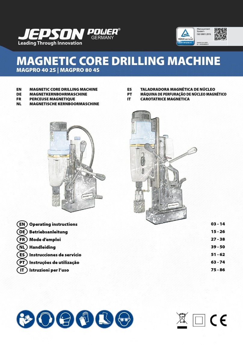
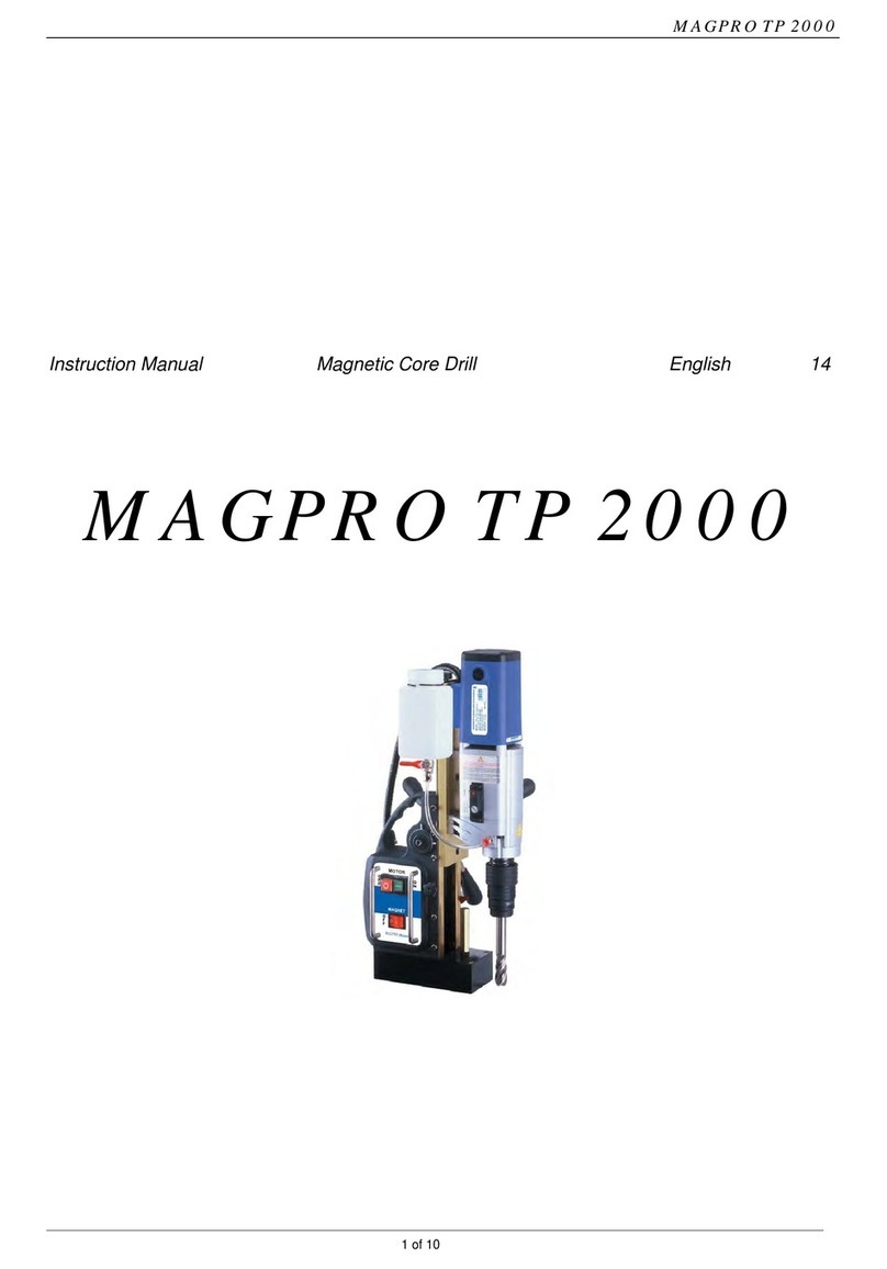
Jepson POWER Magpro40 1S User manual

Magnetic Drilling Machine
MAGPRO 40/ 1S Adjust Swivel
OPERATOR'S MANUAL

EC Declaration of Conformity
according to EC Machinery Directive 2006/42/EC
We, Jepson Power GmbH
Ernst-Abbe-Straße 5
52249 Eschweiler
Germany
declare under our sole responsibility that the product
Product : Electromagnetic Drilling Machine
Type Designation(s): MAGPRO 40/1S Adjust Swivel
Serial No. :
Year ofManufacture : 2019
to which this declaration relates isin conformity with the following standard(s) or other normative
document(s);
EN ISO12100
(2010)
Safety of machinery - General principles for design – Risk assessment
and risk reduction
EN60204-1/A1
(2009)
Safety of machinery - Electrical equipment of machines
Part 1 : General requirements
following the provisions of Directive(s);
2006/42/EC
Directive on the approximation of the laws of Member States relating to machinery
(OJ L157 Jun, 9, 2006)
2006/95/EC Directive on the laws of Member States relating to electrical equipment designed for
use with certain voltage limits (OJ L374 27.12.2006)
Pierre Michiels, Managing Director
Name, Position Eschweiler, 01.01.2019

- 1 -
CONTENTS OF THE MANUAL.
[1]
SPECIFICATIONS OF MAGNETIC DRILLING MACHINE
[2]
SAFETY PROCEDURES
[3]
OPERATING INSTRUCTIONS
[4]
EXTENSION CABLE SELECTION
[5]
MOUNTING OF CUTTERS
[6]
REMEDIES FOR HOLE MAKING PROBLEMS
[7]
CIRCUIT
Page
3
4
6
7
7
8
11
[8]
PART LIST 12
List of Contents with Magnetic Drill Unit Check
List
1 Operator's Manual YES/NO
2 Coolant Bottle YES/NO
3 Pilot Pin for 25mm cutters YES/NO
4 Pilot Pin for 50mm cutters YES/NO
5 5mm Hexagon Key YES/NO
6 Drill drift YES/NO

- 2 -
MAGPRO 40/ 1S Adjust Swivel
(Ref.: 490140S)

- 3 -
[1] SPECIFICATIONS OF MAGNETIC DRILLING MACHINE
[MODEL Magpro40/ 1S Adjust Swivel, Reference: 490140S]
Maximum hole cutting capacity in .2/.3C steel = 40mm dia. x 50mm depth
Motor Unit
Voltages 220/240V(100/110V), 50/60Hz
Rated output 1,100 W
Magnet Size 155 x 78 x 45 mm
Magnet Force at 20°C with
20 mm minimum plate thickness
The use on any material less than 20mm thick
will progressively reduce the magnetic
performance. If possible, substitute material
should be positioned under the magnet and
work piece to equate to a suitable material
thickness. If this is not possible, an alternative
secure method of restraining the machine
MUST be used.
420kgf at drilling point
Overall Dimensions
Height - maximum extended 540mm
Height - minimum 340mm
Width (including Hand wheel) 190mm
Length Overall (including Guard) 230mm
Stroke 150(200)mm
RPM ( No LOAD ) 450
Net Weight 12.0kg
Maximum hand/arm vibration magnitude
(measured at handle during operation in
accordance with ISO5349, using a 22mm
cutter through 13mm MS plate)
0.82 m/s²
Average noise level during cutting at
operators ear position.
90dB(A)

- 4 -
READ BEFORE USING THE MACHINE
[2] SAFETY PROCEDURES
●When using electrical tools, basic safety precautions should always be
followed to reduce the risk of electric shock, fire, and personal injury.
●Do NOT use in wet or damp conditions. Failure to do so may result in
personal injury.
●Do NOT use in the presence of flammable liquids or gases. Failure to do
so may result in personal injury.
●ALWAYS SECURE THE MACHINE WITH THE SAFETY CHAIN WHEN
WORKING VERTICALLY OR OVERHEAD BEFORE STARTING TO OPERATE.
●Always wear approved eye and ear protection when the equipment is in
operation. Failure to do so may result in personal injury.
●Disconnect from the power source when changing cutters or working on
the machine.
●When changing cutters, or removing swarf, ALWAYS wear approved
gloves.
●ALWAYS ENSURE CUTTER RETAINING SCREWS ARE SECURE – they
sometimes vibrate loose when the machine is in continuous use.
●Regularly clear the work area and machine of swarf and dirt, paying
particular attention to the underside of the magnet base.
●With a gloved hand, and after switching off, remove any swarf which might
have gathered around the cutter and arbor before proceeding with the next
hole.

- 5 -
●Before operating the machine, always remove tie, rings, watches and any
loose adornments which might entangle with the rotating machinery.
●Should the cutter become 'fast' in the workpiece, stop the motor
immediately to prevent personal injury. Disconnect from the power
source and turn arbor to and fro. DO NOT ATTEMPT TO FREE THE
CUTTER BY SWITCHING THE MOTOR ON AND OFF.
●If the machine is accidentally dropped, always thoroughly examine the
machine for signs of damage and check that it functions correctly before
trying to drill a hole.
●Regularly inspect the machine and check that nuts and screws are tight.
●Always ensure when using the machine in an inverted position that only the
minimum amount of coolant is used and that care is taken to ensure that
coolant does not drip on to the motor unit.
●On completion of the cut, a slug will be ejected. DO NOT operate the
machine if the ejected slug may cause injury.

- 6 -
[3] OPERATING INSTRUCTIONS
●Keep the inside of the cutter clear of swarf. It restricts the operating depth of
the cutter.
●Ensure that the coolant bottle contains sufficient cutting oil to complete the
required operating duration. Refill as required.
●Occasionally depress the pilot to ensure cutting fluid is being correctly metered.
●To start the machine, first switch on the magnet. And then start the motor by
depressing the GREEN start button.
●Apply light pressure when commencing to cut a hole until the cutter is introduced
into the work surface. Excessive pressure is undesirable, it does not
increase the speed of penetration.
●Always ensure that the slug has been ejected from the previous hole before
commencing to cut the next.
(Right) (Wrong)
●Always cut overlapping holes as illustrated above – do not use excessive pressure
and ensure cutting fluid is reaching teeth of the cutter.
●If the slug sticks in the cutter, move the machine to a flat surface, switch on the
magnet and gently bring the cutter down to make contact with the surface. This will
usually straighten a cocked slug and allow it to eject normally.
●Cutter breakage is usually caused by insecure anchorage and a loosely fitting slide.
(Refer to routine maintenance instructions).

- 7 -
[4] EXTENSION CABLE SELECTION
The machines are factory fitted with a 2 metre length of cable having three
conductors 1.5mm² LIVE, NEUTRAL and EARTH.
If it becomes necessary to fit an extension cable from the power source,
care must be taken in using a cable of adequate capacity. Failure to do so
will result in a loss of traction by the magnet and a reduction of power
from the motor.
Assuming a normal AC supply of the correct voltage, it is recommended
that the following extension lengths shall not be exceeded:
For 110v supply: 3.5metres of 3 core x 1.5mm²
For 230v supply: 26metres of 3 core x 1.5mm² or
17metres of 3 core x 1.0mm²
ALWAYS DISCONNECT THE MACHINE FROM THE POWER SOURCE WHEN
CHANGING CUTTERS.
[5] MOUNTING OF CUTTERS
The machine has normal Weldon shank, 3/4“.
The following procedure is to be used when mounting cutters.
-Take appropriate pilot and place through hole in shank of cutter.
-The machine is delivered with a qick release system. To open the shank turn
the release anti clockwise.
-Put the Weldon arbor into the shank and close the release.

- 8 -
[6] REMEDIES FOR HOLE MAKING PROBLEMS
Problem Cause Remedy
1) Magnetic
base won't hold
effectively
Material being cut may
be too thin for efficient
holding of magnet
Swarf or dirt under
magnet
Irregularity on magnet
face or work-piece
Insufficient current going
to magnet during
drilling cycle
Attach an additional piece of
metal under work-piece where
magnet will be located, or
mechanically clamp magnetic
base to work-piece
Clean magnet
Use extreme care, file only
imperfections flush to surface
Confirm power supply and
output from control unit.
2) Cutter skips
out of
centre-punch
mark at initiation
of cut
Magnetic base is not
holding effectively.
Too much feed pressure
at start of cut.
See causes and remedies above.
Light pressure until a groove is
cut. The groove then serves as
a stabilizer.
Cutter is worn, chipped
or incorrectly sharpened
Replace or re-sharpen.
Sharpening service is available.
Poor centre-
punch mark;
weak pilot spring; pilot
not centred in
centre-punch mark.
Improve centre-punch and/or
replace worn parts.
Worn or bent pilot,
worn pilot hole
Replace parts.

- 9 -
Problem Cause Remedy
3) Excessive
drilling pressure
required.
Incorrectly re-sharpened,
worn or chipped cutter
Re-sharpen or replace
Coming down on swarf
lying on surface of
work-piece
Clean work-piece.
Take care not to start a cut
on swarf
Gibs out of adjustment
or lack of lubrication
Lubricate gib and/or adjust
grub screws
Swarf accumulated
(packed) inside cutter
Clear cutter
Incorrect speed selection. Select appropriate speed.
4) Excessive cutter
breakage
Steel swarf or dirt under
cutter
Remove cutter, clean part
thoroughly and replace
Incorrectly re-sharpened
or worn cutter
Always have a new cutter on
hand to refer to for correct
tooth geometry, together with
instruction sheet
Cutter skipping See causes and remedies (2)
Slide-ways need
adjustment
Tighten slide-way
Cutter not attached
tightly to arbor
Retighten

- 10 -
Insufficient use of cutting
oil or unsuitable type of
oil
Incorrect speed selection.
Fill arbor with an oil of light
viscosity and check to be sure
oil is being metered into
cutter when pilot is
depressed. If not, check
pilot groove and arbor
internally for dirt or apply oil
externally.
Even a small amount of oil is
very effective.
Select appropriate speed.
5) ) Excessive
cutter wear
Incorrectly re-sharpened
cutter.
Insufficient or spasmodic
cutting pressure
Refer to instructions and a
new cutter for proper tooth
geometry
Use sufficient steady pressure
to slow the drill down. This
will result in optimum cutting
speed and chip load.
This manual suits for next models
1
Table of contents
Other Jepson Drill manuals
