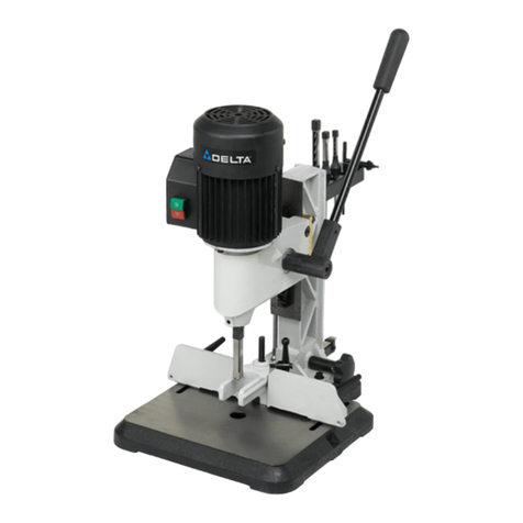
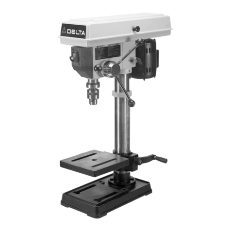
Delta 32-325 User manual

Shown with optional accessory 32-331 Stand
Illustrée sur la plateforme 32-331 (en option)
Aparece con el soporte accesorio 32-331
13-Spindle line Boring
Machine
Machine à percer en
ligne à 13 broches
32-325
Mandrinadora lineal
de 13 husillos
Instruction manual
Manuel d’utilisation
Manual de instrucciones
Français (18)
Español (34)
INSTRUCTIVO DE OPERACIÓN, CENTROS
DE SERVICIO Y PÓLIZA DE GARANTÍA.
LÉASE ESTE INSTRUCTIVO
ANTES DE USAR EL PRODUCTO.
www.deltaportercable.com

2
TABLE OF CONTENTS
IMPORTANT SAFETY INSTRUCTIONS..........................2
SAFETY GUIDELINES - DEFINITIONS...........................2
GENERAL SAFETY RULES .............................................3
ADDITIONAL SPECIFIC SAFETY RULES ......................4
FUNCTIONAL DESCRIPTION .........................................6
CARTON CONTENTS.......................................................6
ASSEMBLY........................................................................7
OPERATION ....................................................................12
TROUBLESHOOTING ...................................................15
MAINTENANCE .............................................................16
SERVICE.........................................................................16
ACCESSORIES..............................................................17
WARRANTY ...................................................................17
FRANÇAIS......................................................................18
ESPAÑOL .......................................................................34
IMPORTANT SAFETY INSTRUCTIONS
Read all warnings and operating instructions before using any tool or equipment. When
using tools or equipment, basic safety precautions should always be followed to reduce the risk of
personal injury. Improper operation, maintenance or modification of tools or equipment could result
in serious injury and property damage. There are certain applications for which tools and equipment
are designed. This product should NOT be modified and/or used for any application other than for which it was
designed.
If you have any questions relative to its application DO NOT use the product until you have written DELTA Machinery and
we have advised you. Contact us online at www.deltaportercable.com or by mail at End User Services, DELTA Machinery,
4825 Highway 45 North, Jackson, Tennessee 38305. In Canada,125 Mural St. Suite 300, Richmond Hill, ON, L4B 1M4)
Information regarding the safe and proper operation of this tool is available from the following sources:
www.powertoolinstitute.com
www.ansi.org
www.osha.gov
SAVE THESE INSTRUCTIONS!
SAFETY GUIDELINES - DEFINITIONS
will result in death or serious injury.
could result in death or serious injury.
may result in minor or moderate injury.
NOTICE
AVIS
AVISO
fr
sp
indicates a practice not related to personal injury which, if not avoided, may result in property
damage.
Some dust created by power sanding, sawing, grinding, drilling, and other construction activities
contains chemicals known to the State of California to cause cancer, birth defects or other reproductive harm.
Some examples of these chemicals are:
that are specially designed to filter out microscopic particles.

3
For your own safety, read the instruction manual1. before operating the machine. Learning the machine’s
Wear eye and hearing protection and always use2. safety glasses. Everyday eyeglasses are not safety
glasses. Use certified safety equipment. Eye protection
equipment should comply with ANSI Z87.1 standards.
Hearing equipment should comply with ANSI S3.19
standards.
Wear proper apparel.3. Do not wear loose clothing, gloves,
caught in moving parts. Nonslip protective footwear is
long hair.
Do not use the machine in a dangerous environment.4. The use of power tools in damp or wet locations or in rain
can cause shock or electrocution. Keep your work area
fingers in danger.
Do not operate electric tools near flammable liquids5. or in gaseous or explosive atmospheres. Motors and
switches in these tools may spark and ignite fumes.
Maintain all tools and machines in peak condition. Keep tools sharp and clean for best and safest
performance. Follow instructions for lubricating and
machines can further damage the tool or machine and/or
Check for damaged parts.7. Before using the machine,
check for any damaged parts. Check for alignment of
moving parts, binding of moving parts, breakage of parts,
and any other conditions that may affect its operation.
A guard or any other part that is damaged should be
properly repaired or replaced with DELTA or factory
Keep the work area clean.8. Cluttered areas and benches
invite accidents.
Keep children and visitors away.9.
potentially dangerous environment. Children and visitors
Reduce the risk of unintentional starting.10. Make sure
that the switch is in the “OFF” position before plugging in
the power cord. In the event of a power failure, move the
switch to the “OFF
unplugging or plugging in the cord.
Use the guards.11. Check to see that all safety devices are
Remove adjusting keys and wrenches before starting12. the machine. Tools, scrap pieces, and other debris can
Use the right machine.13. Don’t force a machine or an
Use recommended accessories.14. The use of accessories
and attachments not recommended by DELTA may cause
Use the proper extension cord.15. Make sure your
will cause a drop in line voltage, resulting in loss of power
and overheating. See the Extension Cord Chart
gauge. The smaller the gauge number, the heavier the
cord.
Secure the workpiece. Use clamps or a vise to hold the
workpiece when practical. Loss of control of a workpiece
Feed the workpiece against the direction of the17. rotation of the blade, cutter, or abrasive surface.
Feeding it from the other direction will cause the
workpiece to be thrown out at high speed.
Don’t force the workpiece on the machine.18. Damage to
Don’t overreach.19. Loss of balance can make you fall into
Never stand on the machine.20.
tool tips, or if you accidentally contact the cutting tool.
Never leave the machine running unattended.21. Turn
the power off. Don’t leave the machine until it comes to a
Turn the machine “22. OFF”, and disconnect the machine
from the power source before installing or removing
accessories, changing cutters, adjusting or changing
set-ups.
switch in the “OFF
Make your workshop childproof with padlocks, master23. switches, or by removing starter keys. The accidental
Stay alert, watch what you are doing, and use24. common sense. Do not use the machine when you
are tired or under the influence of drugs, alcohol, or
medication. A moment of inattention while operating
25. Use of this tool can generate and
disperse dust or other airborne particles, including
wood dust, crystalline silica dust and asbestos dust.
Direct particles away from face and body. Always operate
tool in well ventilated area and provide for proper dust
removal. Use dust collection system wherever possible.
lung disease), cancer, and death. Avoid breathing the
dust, and avoid prolonged contact with dust. Allowing
dust to get into your mouth or eyes, or lay on your skin
may promote absorption of harmful material. Always
use properly fitting NIOSH/OSHA approved respiratory
GENERAL SAFETY RULES
Failure to follow these rules may result in serious personal injury.
4
1. DO NOT OPERATE THIS MACHINE until it is
completely assembled and installed according to
the instructions. A machine incorrectly assembled can
2. OBTAIN ADVICE from your supervisor, instructor,
or another qualified person if you are not thoroughly
familiar with the operation of this machine.
Knowledge is safety.
3. FOLLOW ALL WIRING CODES and recommended
electrical connections to prevent shock or
electrocution.
4. SECURE THE MACHINE TO A SUPPORTING SUR-
FACE. to slide, walk,
or tip over.
5. NEVER START THE MACHINE BEFORE CLEAR-
ING THE TABLE OF ALL OBJECTS
pieces, etc.). Debris can be thrown at high speed.
. NEVER START THE MACHINE with the drill bits
against the workpiece. Loss of control of the
7. PROPERLY LOCK THE DRILL BITS IN THE CHUCK
before operating this machine.
8. USE ONLY DRILL BITS,
recommended in your instruction manual. The
9. USE ONLY DRILL BITS that are not damaged.
Damaged items can cause malfunctions that lead
10. AVOID AWKWARD OPERATIONS AND HAND
POSITIONS. A sudden slip could cause a hand to
move into the bit.
11. KEEP ARMS, HANDS, AND FINGERS away from
12. TURN THE MACHINE “OFF” AND WAIT FOR THE
DRILL BITS TO STOP TURNING prior to cleaning
the work area, removing debris, removing or
table. A moving drill bit, cutting tool, or sanding
13. PROPERLY SUPPORT LONG OR WIDE
pieces. Loss of control of the workpiece can cause
14. NEVER PERFORM LAYOUT, ASSEMBLY OR
SET-UP WORK on the table/work area when the
15. TURN THE MACHINE “OFF”, disconnect the
machine from the power source, and clean the
table/work area before leaving the machine. LOCK
THE SWITCH IN THE “OFF” POSITION to prevent
themselves.
ADDITIONAL INFORMATION regarding the safe
available from the National Safety Council, 1121
refer to the American National Standards Institute
Machines and the U.S. Department of Labor OSHA
1910.213 Regulations.
Failure to follow these rules may result in serious personal injury.
ADDITIONAL SPECIFIC SAFETY RULES
SAVE THESE INSTRUCTIONS.
Refer to them often and use them to instruct others.

5
FIG. A FIG. B
GROUNDED
OUTLET BOX
CURRENT
CARRYING
PRONGS
GROUNDING BLADE
IS LONGEST OF THE 3 BLADES
GROUNDED OUTLET BOX
GROUNDING
MEANS
ADAPTER
POWER CONNECTIONS
A separate electrical circuit should be used for your machines. This circuit should not be less than #12 wire and should
be protected with a time delay fuse. NOTE: Time delay fuses should be marked “D” in Canada and “T” in the US. If
receptacle which will accept the machine’s plug. Before connecting the machine to the power line, make sure the
machine. All line connections should make good contact. Running on low voltage will damage the machine.
SHOCK HAZARD. Do not expose the machine to rain or operate the machine in damp locations.
MOTOR SPECIFICATIONS
sure the switch is in the “OFF” position.
GROUNDING INSTRUCTIONS
SHOCK HAZARD. This machine must be grounded while in use to protect the operator from electric
shock.
1. All grounded, cord-connected machines:
In the event of a malfunction or breakdown, grounding provides a path of least resistance for electric current to reduce
a grounding plug. The plug must be plugged into a matching outlet that is properly installed and grounded in accordance
with all local codes and ordinances.
live terminal.
Check with a qualified electrician or service personnel if the grounding instruction are not completely understood, or if in
doubt as to whether the machine is properly grounded.
accept the machine’s plug, as shown in Fig. A.
Repair or replace damaged or worn cord immediately.
2. Grounded, cord-connected machines intended for use on a supply circuit having a nominal rating less than
150 volts:
If the machine is intended for use on a circuit that has an outlet that looks like the one illustrated in Fig. A,the machine
will have a grounding plug that looks like the plug illustrated in Fig. A. A temporary adapter, which looks like the adapter
illustrated in Fig.
properly grounded outlet is not available. The temporary adapter should be used only until a properly grounded outlet
held in place with a metal screw.
NOTE: In Canada, the use of a temporary adapter is not permitted by the Canadian Electric Code.
SHOCK HAZARD. In all cases, make certain that the receptacle in question is properly grounded. If you
are not sure, have a qualified electrician check the receptacle.

EXTENSION CORDS
plug and matching receptacle which will accept the
to use one heavy enough to carry the current of the
voltage, resulting in loss of power and overheating. Fig.
smaller the gauge number, the heavier the cord.
Fig. D-1
MINIMUM GAUGE EXTENSION CORD
Ampere Total Length Gauge of
Rating Volts of Cord in Feet Extension Cord
0-6 120
up to
25 18 AWG
0-6 120 25-50 16 AWG
0-6 120 50-100 16 AWG
0-6 120 100-150 14 AWG
6-10 120
up to
25 18 AWG
6-10 120 25-50 16 AWG
6-10 120 50-100 14 AWG
6-10 120 100-150 12 AWG
10-12 120
up to
25 16 AWG
10-12 120 25-50 16 AWG
10-12 120 50-100 14 AWG
10-12 120 100-150 12 AWG
12-16 120
up to
25 14 AWG
12-16 120 25-50 12 AWG
12-16 120
FOREWORD
FUNCTIONAL DESCRIPTION
a work space for boring large boards.
NOTICE: The manual cover illustrates the current production model. All other illustrations contained in the manual are
representative only and may not depict the actual labeling or accessories included. These are intended to illustrate
technique only.
CARTON CONTENTS
1
2
3
4
5
6
7
8
9
10 13
12
11 14
15
16
17
18
19
10

7
ASSEMBLY
To reduce the risk of injury, turn unit off and disconnect it from power source before installing and
removing accessories, before adjusting or when making repairs.
UNPACKING AND CLEANING
unpainted surfaces using a soft cloth moistened with mineral spirits, paint thinner or denatured alcohol.
Do not use highly volatile solvents such as gasoline, naphtha, acetone or lacquer thinner for cleaning your
machine.
ASSEMBLY TOOLS REQUIRED
ASSEMBLY TIME ESTIMATE
ACCESSORY 32-331 STAND
ASSEMBLING STAND
use with your boring machine, use Fig. 1 as your guide.
Align the holes in the legs with the holes in the braces,
hole in the leg and the corresponding hole in the brace.
NOTE: Mount all braces to the inside of the legs.
NOTE:
NOTE: Hand-tighten the stand mounting hardware
until you attach the machine to the stand.
Attach the four plastic feet to the bottom of each leg.
ATTACHING THE MACHINE TO THE STAND
Align the four holes of the machine with the four holes on
this process for the three remaining holes.
A
B
C
C
D
D
E
E
Fig. 1
Fig. 2
A
If you use the boring machine without the accessory stand, fasten the machine to a stable supporting
ATTACHING THE MACHINE TO A SUPPORTING SURFACE
B

8
2. Clip the remaining two table slides in the other table
bracket.
Fig. 5.
5. Fasten the table to the table bracket using the two
NOTE: Loosely tighten the hardware for further
of the table and frame in the same manner.
NOTE: Loosely tighten the hardware for further
8. Attach the remaining lock knob to the other side of
the table in the same manner.
ATTACHING THE TABLE
TO THE MACHINE
Fig. 3 Fig. 4
Fig. 5
Fig. 6
Fig. 7
Fig. 8
A
B
C
F
C
B
D
E
L
K
J
H
G
To reduce the risk of injury, turn unit off
and disconnect it from power source before installing
and removing accessories, before adjusting or when
making repairs.

9
table bracket with the large countersunk end of the
NOTE: Loosely tighten the hardware for further
3. Attach the remaining spacer to the opposite end of
fence in the same manner.
shown in Fig. 10.
NOTE: Loosely tighten the two screws, one of which is
gauge.
ATTACHING THE FENCE TO THE MACHINE
Fig. 9
Fig. 10
Fig. 12
Fig. 11
ALIGNING THE FENCE PARALLEL TO THE LINE BORING HEAD
A
B
E
C
D
F
G
E
D
B
C
AA
B
NOTE: Refer to Setting The Fence Stops in the Operation section of this manual.
To reduce the risk of injury, turn unit off
and disconnect it from power source before installing
and removing accessories, before adjusting or when
making repairs.
To reduce the risk of injury, turn unit off and disconnect it from power source before installing and
removing accessories, before adjusting or when making repairs.

10
between the two slides to avoid movement. Clamp the table bracket on the other side of the machine to the
machine frame in the same manner.
STEP 1
fence mounting hardware.
NOTE: The fence stop was removed for clarity.
7. Refer to the following instructions Adjusting The Table Parallel To The Fence.
scales.
IMPORTANT: Make sure that the table
NOTE: The space between the rear of the table and the front of the fence is for chip removal.
4. Remove two clamps temporarily attached in STEP 5
of section Aligning The Fence Parallel To The Line Boring
Head.
A
B
E
L
K
F
G
F
H
G
B
C
A
A
ADJUSTING THE TABLE PARALLEL TO THE FENCE
B
D
Fig. 13 Fig. 14
Fig. 15 Fig. 16
To reduce the risk of injury, turn unit off and disconnect it from power source before installing and
removing accessories, before adjusting or when making repairs.

11
STEP 1)
Fig. 17 Fig. 18
ATTACHING THE OPERATING HANDLE
A
B
C
A
A
B
Fig. 21
Fig. 19
Fig. 20
CA
B
A
To reduce the risk of injury, turn unit off and disconnect it from power source before installing and
removing accessories, before adjusting or when making repairs.
ATTACHING THE BORING BITS TO
THE SPINDLES
To reduce the risk of injury, turn unit off
and disconnect it from power source before installing
and removing accessories, before adjusting or when
making repairs.
NOTE: This machine will only accept bits with 10 mm
shanks.
spindle.
bits.
NOTE:
center spindle, and every other spindle to the right and
ALIGNING THE BORING BITS
To reduce the risk of injury, turn unit off
and disconnect it from power source before installing
and removing accessories, before adjusting or when
making repairs.
ward until ANY ONE
NOTE:
wood at the same time, no alignment is necessary.
2. Hold the operating handle down with the one or
more bits touching the wood.
3. Loosen the set screw of any bit not touching the
wood and let the bit drop. After all bits are evenly
touching the wood, tighten the set screws.

12
1. Remove the protective cover from the guard.
by tightening the screws.
IMPORTANT: Gently bend the guard (A) outward slightly at the center when installing.
To reduce the risk of injury, tighten all assembly hardware at this point.
ATTACHING THE CLEAR PLASTIC GUARD
WRENCH STORAGE
B
A
C
B
AFig. 22 Fig. 23
C
B
OPERATION
OPERATING CONTROLS AND ADJUSTMENTS
STARTING AND STOPPING THE MACHINE
IMPORTANT:
In the event of a power outage (such as a breaker or fuse trip), always move the switch to the “OFF”
position until the main power is restored.
LOCKING THE SWITCH IN THE “OFF” POSITION
A
A
Fig. 24 Fig. 25
Make sure that the switch is in the “OFF” position before plugging in the power cord. In the event
of a power failure, move the switch to the “OFF” position. An accidental start-up can cause injury.
To reduce the risk of injury, turn unit off and disconnect it from power source before installing and
removing accessories, before adjusting or when making repairs.
To reduce the risk of injury, turn unit off and disconnect it from power source before installing and
removing accessories, before adjusting or when making repairs.

13
Fig. 28
Fig. 29
C
D
BA
LOWERING THE BORING HEAD
return the handle to the “up” position.
OPERATING HANDLE
To reduce the risk of injury, turn unit off
and disconnect it from power source before installing
and removing accessories, before adjusting or when
making repairs.
way.
CONTROLLING THE DOWNWARD
TRAVEL OF THE BORING HEAD
To reduce the risk of injury, turn unit off
and disconnect it from power source before installing
and removing accessories, before adjusting or when
making repairs.
A stop is provided to set the depth of the boring bits. To
control the downward travel of the boring head, loosen
machine, ensures an even depth of cut. Set the right
depth stop first. Then lower the boring head until it
contacts the right depth stop and set the left depth stop
accordingly.
ADJUSTING THE STOP SCREW
To reduce the risk of injury, turn unit off
and disconnect it from power source before installing
and removing accessories, before adjusting or when
making repairs.
with the “0” mark on the scale.
same time that the bits touch the table.
3. If the bits do not touch the table, loosen the stop
time that the bits touch the table. Tighten the stop
MOVING THE FENCE AND TABLE
To reduce the risk of injury, turn unit off
and disconnect it from power source before installing
and removing accessories, before adjusting or when
making repairs.
Fig. 26
A
B
D
C
A
B
EFig. 27

14
SETTING THE FENCE STOPS
To reduce the risk of injury, turn unit off and disconnect it from power source before installing and
removing accessories, before adjusting or when making repairs.
NOTE:
moving the hub of the handle on the nut located underneath the hub.
PROJECT EXAMPLE
Assignment:
edge of the workpiece. Bore an additional series of holes, in
the workpiece.
the left edge of the workpiece against the left stop
“ON”, lower the handle, and
bore the holes.
NOTE:
so the workpiece can contact the fence surface.
left stop can be pushed back so that the workpiece
can contact the fence surface. Bore the additional
Fig. 30 Fig. 31
Fig. 32
Fig. 33
G
F
G
E
F
B
D
BC
D
C A
MACHINE USE

15
Note that the right end of the workpiece is positioned
bored with a 32 mm center distance between each
hole.
piece along the fence and push down on the
pin is in the last hole previously bored. This aligns
allowing the workpiece to fit flush against the
fence.
3. Bore the additional thirteen holes in the workpiece
other.
LINE BORING
Fig. 34
Fig. 35
Fig. 36
A
B
A
TROUBLESHOOTING
For assistance with your machine, visit our website at www.deltaportercable.com for a list of service centers or call the

MAINTENANCE
To reduce the risk of injury, turn unit off and disconnect it from power source before installing and
removing accessories, before adjusting or when making repairs.
KEEP MACHINE CLEAN
Wear certified safety equipment for eye, hearing and respiratory protection while using compressed air
FAILURE TO START
Should your machine fail to start, check to make sure the prongs on the cord plug are making good contact in the outlet.
Also, check for blown fuses or open circuit breakers in the line.
LUBRICATION & RUST PROTECTION
commercially available protective product designed for this purpose. Follow the manufacturer’s instructions for use and
safety.
lubricant and a can of degreaser. Apply the spray lubricant and polish the table surface with the scouring pad. Degrease
the table, then apply the protective product as described above.
REPLACEMENT PARTS
Use only identical replacement parts. For a parts list or to order parts, visit our website at www.deltaportercableservicenet.
FREE WARNING LABEL REPLACEMENT
If your warning labels become illegible or are missing, call
for a free replacement.
SERVICE AND REPAIRS
All quality tools will eventually require servicing and/or replacement of parts. For information about DELTA Machinery, its
you can also find answers to most frequently asked questions 24 hours/day.
4825 Highway 45 North, Jackson, Tennessee 38305
number, type, serial number, date code, etc.)
SERVICE

17
Since accessories other than those offered by DELTA have not been tested with this product, use of
such accessories could be hazardous. To reduce the risk of injury, only DELTA recommended accessories should be
used with this product.
name of your nearest supplier.
ACCESSORIES
Five Year Limited New Product Warranty
DELTA will repair or replace, at its expense and at its option, any new DELTA machine, machine part, or machine accessory which in normal
use has proven to be defective in workmanship or material, provided that the customer returns the product prepaid to a DELTA factory service
center or authorized service station with proof of purchase of the product within five years and provides DELTA with reasonable opportunity
to verify the alleged defect by inspection. For all refurbished DELTA product, the warranty period is 180 days. DELTA will not be responsible
for any asserted defect which has resulted from normal wear, misuse, abuse or repair or alteration made or specifically authorized by anyone
other than an authorized DELTA service facility or representative. Under no circumstances will DELTA be liable for incidental or consequential
damages resulting from defective products. Some states do not allow the exclusion or limitation of incidental or consequential damages, so
the above limitation or exclusion may not apply to you. This warranty is DELTA’s sole warranty and sets forth the customer’s exclusive remedy,
with respect to defective products; all other warranties, express or implied, whether of merchantability, fitness for purpose, or otherwise, are
expressly disclaimed by DELTA. For further detail of warranty coverage and warranty repair information, visit www.deltaportercable.com or call
(888) 848-5175. This warranty gives you specific legal rights and you may have other rights which vary in certain states or provinces.
WARRANTY
To register your tool for warranty service visit our website at www.deltaportercable.com.
LATIN AMERICA: This warranty does not apply to products sold in Latin America. For products sold in Latin America,
see country specific warranty information contained in the packaging, call the local company or see website for warranty
information.

18
LES INSTRUCTIONS IMPORTANTES DE SURETE
Lire toutes instructions d'avertissements et opération avant d'utiliser n'importe
quel outil ou n'importe quel équipement. En utilisant les outils ou l'équipement, les précautions de
sûreté fondamentales toujours devraient être suivies pour réduire le risque de blessure personnelle.
L'opération déplacée, l'entretien ou la modification d'outils ou d'équipement ont pour résultat la
blessure sérieux et les dommages de propriété. Il y a de certaines applications pour lequel outils et l'équipement
sont conçus. Ce produit NE devrait être modifié en aucune façon et/ou utilisé pour aucune application autre que celle pour
laquelle il a été conçu.
Dans Canada,
125 Mural St. Suite 300, Richmond Hill, ON, L4B 1M4.
www.powertoolinstitute.com
www.ansi.org
U.S. Department of Labor regulations www.osha.gov
CONSERVER CES DIRECTIVES!
MESURES DE SÉCURITÉ - DÉFINITIONS
causera la mort ou des
blessures graves.
pourrait se solder par
un décès ou des blessures graves.
pourrait se solder par
des blessures mineures ou modérées.
NOTICE
AVIS
AVISO
fr
sp
indique une pratique ne posant aucun risque de dommages corporels mais qui par contre, si rien
pourrait poser des risques de dommages matériels.
Les scies, meules, ponceuses, perceuses ou autres outils de construction peuvent produire
des poussières contenant des produits chimiques reconnus par l’État californien pour causer cancers,
malformations congénitales ou être nocifs au système reproducteur. Parmi ces produits chimiques, on retrouve :

19
Pour sa sécurité personnelle, lire la notice d’utilisation,1. avant de mettre la machine. En marche, et pour aussi
apprendre l’application et les limites de la machine ainsi
Portez des dispositifs de protection des yeux et de l'ouïe.2. Utilisez toujours des lunettes de sécurité. Des lunettes
ANSI Z87.1. Les dispositifs de protection de
ANSI S3.19.
Porter une tenue appropriée.3.
se trouvent pris dans les pièces mobiles peuvent entraîner
des blessures.
Ne pas utiliser la machine dans un environnement4. dangereux.
endroits humides ou sous la pluie peut entraîner des
Ne pas utiliser d’outils électriques à proximité de5. liquides inflammables ou dans une atmosphère gazeuse
ou explosive. Les moteurs et interrupteurs des outils
vapeurs.
Garder les outils et les machines en parfait état.
et changer les accessoires. Les outils et les machines mal
des blessures.
Inspecter les pièces pour déceler tout dommage.7. Avant
mobiles et si ces pièces ne se coincent pas, la rupture
de pièces, ou toute autre condition pouvant en affecter le
blessures.
Garder l’aire de travail propre.8.
Garder les enfants et les visiteurs à distance.9. L’atelier
visiteurs peuvent se blesser.
Éviter le démarrage accidentel.10. S’assurer que l’interrupteur
est sur « OFFARRêT) avant de brancher le cordon. En
« OFFARRêT
des blessures.
Utiliser les dispositifs protecteurs11. .
Enlever les clés de réglage et celles de serrage avant de12. mettre la machine en marche. Les outils, les chutes et les
Utiliser la bonne machine.13. Ne pas forcer la machine ou
s’ensuivre.
Utiliser les accessoires recommandés.14. L’utilisation
endommager la machine et blesser l’utilisateur.
RÈGLES DE SÉCURITÉ GÉNÉRALES
L’inobservation de ces règles peut conduire à des blessures graves.
Utiliser le cordon prolongateur approprié.15. S’assurer
machine. Un cordon d’un calibre insuffisant entraînera une
perte de tension d’où une perte de puissance et surchauffe.
Tableau sur Les Cordons
petit, plus le fil est gros.
Fixer la pièce.
causer des dommages.
Avancer la pièce dans le sens contraire à la rotation17. de la lame, de la fraise ou de la surface abrasive.
L’alimentation dans l’autre sens peut entraîner une
18. Ne pas forcer la machine en avançant la pièce trop vite.
Des dommages et/ou des blessures peuvent s’ensuivre.
Ne pas se pencher au-dessus de la machine.19. Une perte
marche et causer des blessures.
Ne jamais monter sur la machine.20. On peut se blesser
gravement si la machine bascule ou si l’on touche
accidentellement son outil tranchant.
Ne jamais laisser la machine en marche sans21. surveillance. Couper le courant. Ne pas quitter la
enfant ou un visiteur pourrait se blesser.
Mettre la machine à l’arrêt «22. OFF » (ARRÊT) et
la débrancher avant d’installer ou d’enlever des
accessoires, changer les coupeurs, d’ajuster ou de
changer des montages.
OFF »
ARRêT
blessures.
Mettre l’atelier à l’abri des enfants au moyen de23. cadenas, d’interrupteurs principaux ou en enlevant
les boutons des dispositifs de mise en marche. Le
visiteur peut entraîner des blessures.
Rester vigilant, attentif, et faire preuve de bon sens.24. Ne
pas utiliser la machine lorsque l’on est fatigué ou sous
l’influence de drogues, d’alcool ou de médicaments. Un
peut entraîner des blessures graves.
25. L'utilisation de cet outil peut
produire et disperser de la poussière ou d'autres
particules en suspension dans l'air, telles que la sciure
de bois, la poussière de silicium cristallin et la poussière
d'amiante.
NIOSH/
OSHA

20
RÈGLES SPÉCIFIQUES ADDITIONNELLES DE SÛRETÉ
L’inobservation de ces règles peut conduire à des blessures graves.
CONSERVER CES DIRECTIVES.
Les consulter souvent et les utiliser pour donner des directives aux autres.
1. NE PAS UTILISER CETTE MACHINE tant qu’elle
corporels graves.
2. DEMANDER CONSEIL
l’on n’est pas complètement familier avec l’utilisation
3. SE CONFORMER AUX NORMES DU CODE EN
MATIÈRE DE CÂBLAGE
4. ARRIMER SOIGNEUSEMENT LA MACHINE À UN
SUPPORT. Les vibrations pourraient faire glisser, bouger
la machine ou la renverser.
5. NE JAMAIS METTRE LA MACHINE EN
MARCHE AVANT D’AVOIR ÉLIMINÉ TOUT
OBJET PRÉSENT SUR LA TABLE DE TRAVAIL
. NE JAMAIS METTRE LA MACHINE EN MARCHE
alors que les mèches sont en contact avec la pièce
travailler pourrait occasionner des dommages
corporels graves.
7. VERROUILLER SOIGNEUSEMENT LES MÈCHES
DANS LE MANDRIN
la machine.
8. UTILISER SEULEMENT DES MÈCHES dont le
diamètre de tige respecte les recommandations du
ou corporels.
9. UTILISER SEULEMENT DES MÈCHES en parfait
dommages corporels.
10. ÉVITER TOUTE UTILISATION OU POSITION DES
MAINS MALAISÉE.
pourrait provoquer un contact involontaire des
mains avec une mèche.
11. PROTÉGER BRAS, MAINS ET DOIGTS de tout
dommage corporel grave.
12. ARRÊTER LA MACHINE PUIS ATTENDRE L’ARRÊT
COMPLET DES MÈCHES avant de nettoyer l’aire de
travailler, ou modifier l’angle de la table de travail. Une
mèche, un organe de coupe ou un tambour de
dommages corporels graves.
13. SOUTENIR SOIGNEUSEMENT TOUTE PIÈCE À
TRAVAILLER LONGUE OU LARGE. Une perte de
des dommages corporels graves.
14. NE JAMAIS EFFECTUER DE MISE EN PLACE,
MONTAGE OU CONFIGURATION
de travail alors que la machine fonctionne pour
15. ARRÊTER LA MACHINE,
de laisser la machine. VERROUILLER
L’INTERRUPTEUR EN POSITION d’ « OFF »
(ARRÊT)
DES INFORMATIONS COMPLÉMENTAIRES sur
Other manuals for 32-325
1
Table of contents
Languages:
Other Delta Drill manuals

Delta
Delta 17-925 User manual

Delta
Delta DP300L User manual

Delta
Delta ShopMaster DP200 User manual

Delta
Delta 2000 User manual

Delta
Delta 900585 User manual

Delta
Delta 6 plus 6 15" Drill Press User manual

Delta
Delta ShopMaster DP350 User manual

Delta
Delta CL120 User manual

Delta
Delta 1275 User manual

Delta
Delta 70-200 User manual