Jesco GW 702 User manual

GW 702
Gas Warning Device for Chlorine Gas, Chlorine Dioxide and Ozone
EN 02 Operating Manual
Read this operating manual before using the equipment.
To be retained for future reference.
Dosing Liquids
Conveying Gases
Control Systems

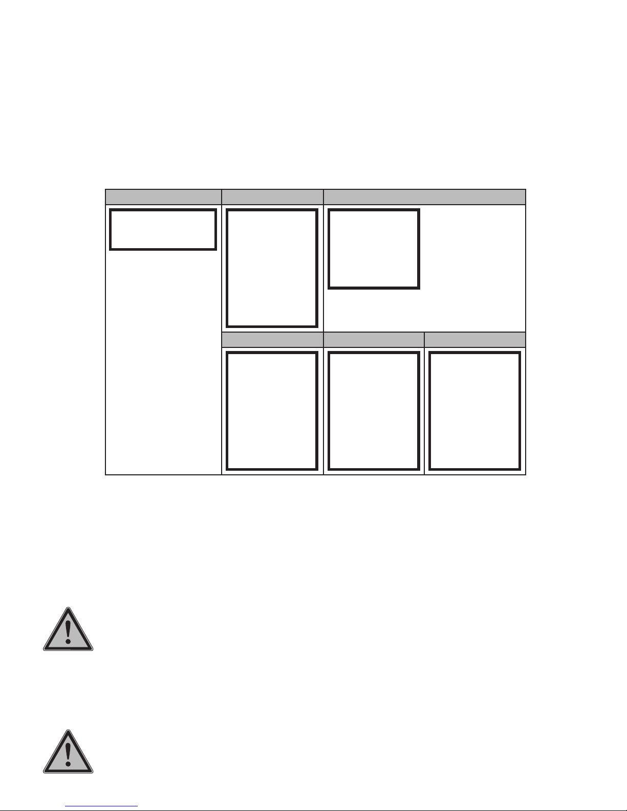
2 | Operating Manual GW 702 | Table of Contents
Table of Contents
1. General and Safety Instructions................................................................................................................................3
2. Before start-up...........................................................................................................................................................5
2.1 Proper intended use .......................................................................................................................................... 5
2.2 Scope of delivery ............................................................................................................................................... 5
2.3 Start-up procedure ............................................................................................................................................ 5
2.4 Part numbers .................................................................................................................................................... 5
3. Functional range........................................................................................................................................................6
3.1 Measurement amplifier GW 702......................................................................................................................... 6
3.2 Sensor.............................................................................................................................................................. 6
3.3 Power supply backup system (accessory)............................................................................................................ 6
4. Dimensioned drawings..............................................................................................................................................7
5. Technical data............................................................................................................................................................8
6. Assembly and Installation.......................................................................................................................................11
6.1 Measurement amplifier GW 702....................................................................................................................... 11
6.2 Sensor............................................................................................................................................................ 12
6.3 Wiring diagram................................................................................................................................................ 13
6.4 Drill template................................................................................................................................................... 14
7. Operation..................................................................................................................................................................15
7.1 Setting parameters .......................................................................................................................................... 15
7.2 Menu Overview ............................................................................................................................................... 16
7.3. Code.............................................................................................................................................................. 16
7.4 Language........................................................................................................................................................ 16
8. Configuration ...........................................................................................................................................................17
8.1 Sensors .......................................................................................................................................................... 17
8.2 Sensor Slope................................................................................................................................................... 18
8.3 Sensor Test ..................................................................................................................................................... 18
9. Operating Modes......................................................................................................................................................19
10. Relays.....................................................................................................................................................................20
10.1 Action in the event of an alarm or fault............................................................................................................ 20
10.2 Configuration................................................................................................................................................. 21
10.3 Relay Test ..................................................................................................................................................... 21
11. Analogue Output and Interface .............................................................................................................................22
11.1 Analogue output ............................................................................................................................................ 22
11.2 Interface ....................................................................................................................................................... 22
12 Check function........................................................................................................................................................22
13. Maintenance ..........................................................................................................................................................23
13.1 Replacing the sensor ..................................................................................................................................... 23
13.2 Calibrating the sensor.................................................................................................................................... 23
13.3 Functional test of the sensor with test gas application...................................................................................... 24
13.4 Replacing the fuse......................................................................................................................................... 24
13.5 Display Contrast ............................................................................................................................................ 24
13.6 Power supply backup system (accessory)........................................................................................................ 24
13.7 Disposal........................................................................................................................................................ 24
14. Service ...................................................................................................................................................................25
15. Spare parts.............................................................................................................................................................26
Device revision ............................................................................................................................................................26
Index.............................................................................................................................................................................27
Warranty claim.............................................................................................................................................................28
CE declaration of conformity......................................................................................................................................29
General and Safety Instructions | Operating Manual GW 702 | 3
1. General and Safety Instructions
1.1 General
This operating manual contains basic instructions to be followed during installation, operation and main-
tenance. It is therefore essential that the Operating Manual be read by the installation technician before
installing and commissioning the pump/system, as well as by the relevant operating personnel/operating
company of the unit. The Operating Manual must remain accessible at the dosing pump/system for refer-
ence at all times. Besides the general safety instructions in this "Safety" section, the special safety instruc-
tions in the other sections are also to be followed.
1.2 Identification of safety instructions in the operating manual
This operating manual contains essential safety instructions. Failure to observe this information may endan-
ger other people and the unit. The safety instructions are identified by the following symbols:
WARNING!
Refers to a potentially hazardous situation. Failure to follow this instruction may lead to death or severe
injury.
CAUTION!
Refers to a potentially hazardous situation. Failure to follow this instruction may lead to minor injury or dam-
age to property.
ATTENTION! or NOTICE!
Failure to comply with this safety instruction may result in damage to the device and endanger its operation.
IMPORTANT!
This refers to additional information to facilitate operation and ensure the smooth running of the equipment.
Notices attached directly to the unit, such as e.g. cable markings must definitely be observed and kept in
completely legible condition.
1.3 Personnel qualifications and training
The personnel employed for operation, maintenance, inspection, and installation must be suitably qualified
for this work. The responsibilities, areas of competence and personnel supervision must be clearly defined
by the operating company. Personnel who do not have the required know-how must be duly trained and
instructed. If necessary, this can also be done by the manufacturer/supplier on behalf of the operating
company. In addition, the operating company must also ensure that the relevant personnel are fully familiar
with and have understood the contents of the operating manual.
1.4 Important safety instructions
Basic safety precautions should always be followed when installing and using this electrical equipment.
These include the following:
READ AND FOLLOW ALL INSTRUCTIONS!
WARNING!
To reduce the risk of injury, do not permit children to use this product unless they are closely supervised at
all times.
WARNING!
Risk of electric shock. Connect the device only to a SCHUKO socket outlet protected by a ground fault circuit
interrupter (GFCI). Contact a qualified electrician if you cannot verify that the connector is protected by a
GFCI.

4 | Operating Manual GW 702 | General and Safety Instructions
Do not bury the cable. Secure the cable to avoid damage by lawn mowers, hedge trimmers and other equip-
ment.
WARNING!
To reduce the risk of electric shock, replace the cable immediately if damaged.
WARNING!
To reduce the risk of electric shock, do not use an extension cable to connect the device to the power sup-
ply; use an appropriately located socket.
KEEP THESE INSTRUCTIONS IN A SAFE PLACE!
1.5 Hazards due to failure to follow safety instructions
Failure to follow the safety instructions may endanger not only persons, but also the environment and the
device. Failure to follow the safety instructions may invalidate any damage claims.
Non-compliance with the safety instructions may give rise to the following hazards:
• Failure of major functions of the device.
• Danger to persons due to electrical, mechanical and chemical effects.
1.6 Safety awareness at work
The safety instructions contained in this operating manual must be observed. The operating company is
responsible for ensuring compliance with local safety regulations. Any faults that could affect safety must be
rectified immediately.
1.7 Safety instructions for the operating company/operator
A safe and ecologically beneficial disposal of process materials as well as replacement parts must be
ensured. (Legal requirements must be observed)
Risks from electric power must be excluded (for further details, refer to the VDE1) regulations and the
requirements of the local public utilities as well as section 1.4).
1) VDE = Association of German Electrical Engineers
1.8 Safety instructions for inspection, maintenance and installation work
The operating company must ensure that all maintenance, inspection and installation work is carried out by
authorised and duly qualified personnel, who have read and understood this operating manual.
Before carrying out installation and maintenance works, always make sure that the unit is disconnected
from power supply. The device must be prevented from being switched on again during the above work.
Only in this state may additional modules be mounted or removed and connections be made. Non-compli-
ance can result in damage to the unit and invalidate the warranty. All safety and protective equipment must
be reattached and activated immediately after the work has been completed.
1.9 Unauthorised modification and production of spare parts
The device may only be modified or converted in consultation with the manufacturer. If errors and hazards
result during operation due to incorrect configuration of the unit, any liability is excluded.
Use only the manufacturer's spare parts and sensors. Otherwise the warranty is invalidated.
Before start-up | Operating Manual GW 702 | 5
2. Before start-up
2.1 Proper intended use
The device is intended for the following purpose only: monitoring and displaying combustible and/or toxic
gases as well as oxygen. Operating safety is guaranteed only if the device is used for its intended purpose.
All other types of use are prohibited and will invalidate the warranty. The operating conditions described in
chapter 5 "Technical Data" must be observed!
2.2 Scope of delivery
IMPORTANT!
Carefully unpack the product and any accompanying accessories, so that no small parts are left inside the
packaging. Compare the delivery content with the delivery note immediately. If there are any discrepancies,
determine the cause.
The scope of delivery includes:
• Measurement amplifier GW 702
• 1 or 2 sensor elements (depending on version)
• 1 or 2 sensor holders, incl. 10 m cable (depending on version)
• 2 or 4 pipe clamps d25 (depending on version)
• Operating Manual
2.3 Start-up procedure
• Reading the operating manual
• Assembly and installation (section 6)
• Checking the function (see chapter „12 Check function“ on page 22).
2.4 Part numbers
Part No. Description
23600250 Gas warning device GW 702 for chlorine gas, 1 sensor
23600251 Gas warning device GW 702 for chlorine gas, 2 sensors
23600252 Gas warning device GW 702 for chlorine dioxide, 1 sensor
23600253 Gas warning device GW 702 for chlorine dioxide, 2 sensors
23600254 Gas warning device GW 702 for ozone, 1 sensor
23600255 Gas warning device GW 702 for ozone, 2 sensors

6 | Operating Manual GW 702 | Functional range
3. Functional range
The gas warning device is a stationary measuring, control and warning device that is in continuous opera-
tion and is used to measure toxic gases. It consists of several components that act as a single unit. It is both
reliable and easy to assemble and maintain.
The gas warning device is part of the safety system for gas conducting systems and can be used with the
following gases:
Measuring gas
Chlorine gas (Cl2)
Chlorine dioxide (ClO2)
Ozone (O3)
Table 3.1: Measuring gas, other gases on request
Case of application: Chlorine Gas
The sensor is installed in the chlorine gas room; at a freely accessible location approx. 30 cm above the
floor. Chlorine gas is heavier than air and descends when it escapes. The sensor detects escaped chlorine
gas. The changed electrical behaviour of the sensor is registered by the measurement amplifier. On the
measurement amplifier this is indicated as chlorine content in the air. If the alarm thresholds set have been
exceeded, alarm conditions are displayed or relays switched to notify the relevant persons.
3.1 Measurement amplifier GW 702
The measurement amplifier GW 702 is the central control unit and is installed where it can be accessed by
operators. It allows measurements to be checked and alarm thresholds set.
It evaluates the electrical behaviour of the sensor. The digital display shows the gas content of the air in the
monitored room.
The configuration of the measurement amplifier is possible without sensor connected.
3.2 Sensor
The sensor consists of
• Sensor holder with 10 m cable
• Sensor element
It has a robust and corrosion-proof housing for industrial applications.
IMPORTANT!
The length of the cable must neither be extended nor shortened.
The sensor is an electronic measuring cell that works according to the electro-chemical principle. The sen-
sor element on the sensor holder can be replaced easily.
3.3 Power supply backup system (accessory)
The backup system is a uninterruptible power supply (battery) that feeds the gas warning device system in
the event of a power failure. This supply will keep the device working for approximately 10 hours.
Dimensioned drawings | Operating Manual GW 702 | 7
4. Dimensioned drawings
Fig. 4.1: Measurement amplifier GW 702
Fig. 4.2: Sensor holder
380
380
210
Fig. 4.3: Power supply backup system (accessory)

8 | Operating Manual GW 702 | Technical data
5. Technical data
Measurement amplifier GW 702
Supply voltage 230 V AC +6/-10 %, 50/60 Hz
alternatively 110 V AC, 50/60 Hz
Power consumption 10 VA
Fuse 230 V: T(S) 63 mA, 5 x 20 mm
110 V: T(S) 125 mA, 5 x 20 mm
Display LCD display
• 2 x 16 characters, lit
• Display of measured value, switching states of relays, status information
of sensor and alarm
• Menu language German, English, French and Spanish
Controls Keypad with 5 keys
Relay 3 contacts, 6 A, 250 V AC, potential-free
Max. 550 VA ohmic resistive load (with RC protective circuit, suppression
element)
• Relay 1, fixed assigned sensor 1 and sensor 2
• Relay 2, fixed assigned sensor 1 and sensor 2
• Relay 3 (alarm), freely assignable sensor 1 and / or sensor 2
Analogue output 0/4 … 20 mA, galvanically isolated
max. working resistance 500 Ω
to be assigned sensor 1 or sensor 2
Number of sensors Max. 2
Alarm thresholds 2 limits, pre-configured, freely adjustable
Chlorine (Cl2) Chlorine dioxide (ClO2) Ozone (O3)
Limit 1 2 ppm 0.2 ppm 0.2 ppm
Limit 2 9.5 ppm 1 ppm 1 ppm
Digital input 1
Interface RS 485 (option)
Signal generator -
Dimensions (W x H x D) 165 x 160 x 80 mm
Installation Wall assembly
Housing material ABS
Protection class IP 65
Weight ~ 1.0 kg
Cable entry point PG connections
3x M12 x 1.5 (cable diameter 3 … 6 mm)
3x M16 x 1.5 (cable diameter 5 … 10 mm)
Connections Spring terminals for cable up to max. 1.5 mm2
Operating temperature 0 … 50 °C
Storage temperature -20 … +65 °C
Air humidity 0 … 90 % rH, non-condensing

Technical data | Operating Manual GW 702 | 9
Sensors
Measuring gas Chlorine (Cl2) Chlorine dioxide (ClO2) Ozone (O3)
Measuring range 0 … 9.99 ppm 0 … 1 ppm 0 … 1 ppm
Measuring principle Electro-chemical cell. Two or more electrodes arranged in an electrolyte.
An electro-chemical reaction takes place at the electrode. The sensor
supplies a measuring current, which is proportional to the corresponding
gas concentration in the air. In the measurement amplifier this current
is calculated with the corresponding sensor slope and displayed as
measured value in ppm.
Reaction time approx. 30 s
Dimensions (L x ø) 135 x ø 33 mm
Housing material PVC
Protection class IP 54 (except for gas inlet)
Weight approx. 0.2 kg
Cable 10 m
Ambient temperature -10 … +40 °C
Storage temperature -10 … +40 °C
Air humidity 10 … 90 % rH, non-condensing
Air pressure 900 … 1100 hPa
Service life 2 years, depending on the operating conditions
10 | Operating Manual GW 702 | Technical data
Power supply backup system (accessory)
Override time max. 10 h
Changeover time 2 … 6 ms
Power supply 220 / 230 / 240 V AC, 50/60 Hz
Mains output supply 230 V AC ±10%, 50/60 ±1 Hz
Output rated current 2.2 A
Protection • Overload
• Full discharge
• Short circuit
• Overtemperature
Charge time 8 h
Battery 12 V DC, 7 Ah, maintenance-free, 3 … 5 years service life
Interface USB, RS 232
Ambient temperature 0 … 45 °C
Storage temperature 0 … 45 °C
Air humidity 0 … 90 % rH, non-condensing
Housing Steel sheet, powder-coated, lockable
Dimensions (W x H x D) 380 x 380 x 210 mm
Protection class IP 66
Weight approx. 18 kg
Assembly and Installation | Operating Manual GW 702 | 11
6. Assembly and Installation
ATTENTION!
Electrical connections must only be performed by specialist personnel in accordance with relevant installa-
tion requirements.
ATTENTION!
Make sure the device is de-energised when working on it. The power supply must only be switched on after
assembly and electrical connections have been completed.
IMPORTANT!
Note the power supply specified on the rating plate.
IMPORTANT!
Where possible, a continuous cable from sensor to the measuring input should be used. An extension of the
cable by plugs or terminal sockets increases the risk of faults caused by contamination, humidity or exces-
sive transition resistances.
ATTENTION!
Input, output and control lines and cables must always be kept separate. In particular, they must be routed
away from power circuit lines!
NOTE!
All cables must be routed to protect them from mechanical damage. Strain relief must be provided near the
cable entry point.
Stray interference will falsify the measurement. Power supply and measuring lines at close proximity should
only cross at a 90° angle. The permissible length of the measuring cables must be adhered to with regard
to the sensor used. When measuring ensure that the (plug) connections are clean and dry and that the lines
do not become brittle due to sharp buckling. The shielded cables normally used for such measuring lines
must be of the quality specified.
6.1 Measurement amplifier GW 702
The electrical installation for the gas warning device must contain a separating device (e.g. an automatic
circuit breaker) to ensure reliable separation from the power supply.
The device is designed for a fixed installation connected to a power supply of 230 V /AC. The device cor-
responds to protection class I in accordance with EN 60335 and must be connected to a protective earth
conductor (PE).
When connecting to the relays, note that inductive loads must be dejammed. If this is not possible, the strip
relay contact on the device terminal must be protected by an RC protective circuit / suppression element.
For DC voltage the relays or contactor coil must be dejammed with a freewheeling diode.
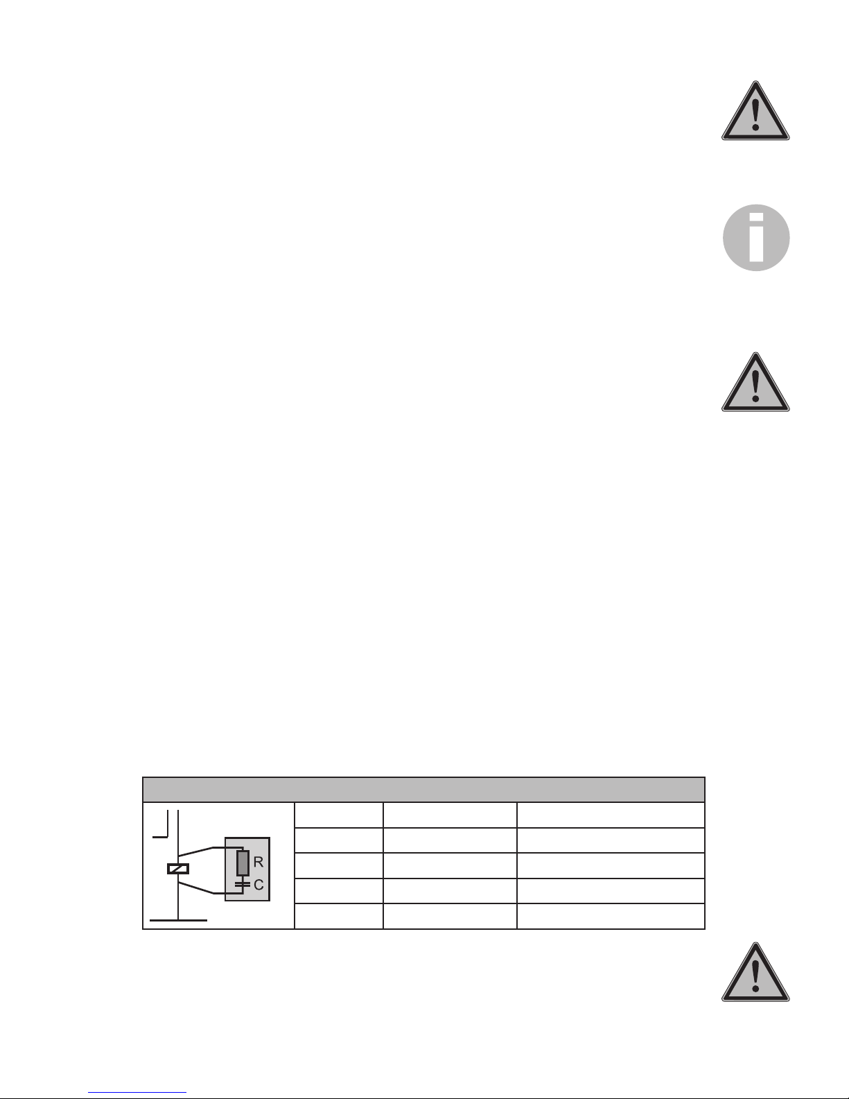
RC protective circuit / suppression element
Current Capacitor C Resistor R
< 60 mA 10 nF 260 V 390 Ohm 2 Watt
< 70 mA 47 nF 260 V 22 Ohm 2 Watt
< 150 mA 100 nF 260 V 47 Ohm 2 Watt
< 1 A 220 nF 260 V 47 Ohm 2 Watt
ATTENTION!
The assembly location must be selected so that the device is not subject to any mechanical load or chemi-
cal exposure in any way.

12 | Operating Manual GW 702 | Assembly and Installation
• First, remove the terminal cover.
• Prepare three drill holes (max. M5).
• Take into account at the top hole, that you can suspend the device
or push it under.
• To suspend it, set the top hole 120 mm above the two lower
holes.
• To push it under, the distance must be 135 mm.
• In both cases the screw must protrude at least 3 mm.
• Suspend the device on the top screw or push it underneath.
• Fix it with the two lower screws.
• Re-attach the terminal cover or proceed directly to the connec-
tions.
6.2 Sensor
• Up to 2 sensors can be connected to the measurement amplifier
GW 702.
• The connection of a sensor takes place by means of the shielded
3-wire cable attached to the sensor holder.
IMPORTANT!
The length of the cable must neither be extended nor shortened.
• All input and output wires and cables must be shielded. The
shielding must be applied on one side only.
• The gas inlet of the sensor must be kept clear of dust and
contamination.
• The wall mounting is carried out with the sensor opening facing
down, close to the ground (at a height of approx. 30 cm).
• During assembly make sure that the sensor remains accessible for
maintenance work.
• Keep a minimum distance of 10 cm between the sensor opening
and other fixtures.
aUnscrew the O-ring of the sensor holder.
bTake the sensor element from the separate packaging and remove
the transport protection. (shorting jumper).
cFit the sensor element into the sensor holder without force. Note,
that the correct seating position is indicated by a groove. Ensure that the
connecting pins are not bent. Check the correct seating of the seal and
screw on the union nut again.
dMount the completed sensor perpendicular with two mounting
brackets, with the sensor element facing down, about 30 cm above the
ground. Ensure that the sensor is not subjected to any strong wind, heat
or direct sunlight and that the sensor element can not get wet at any
time.
a
b
c
d

Assembly and Installation | Operating Manual GW 702 | 13
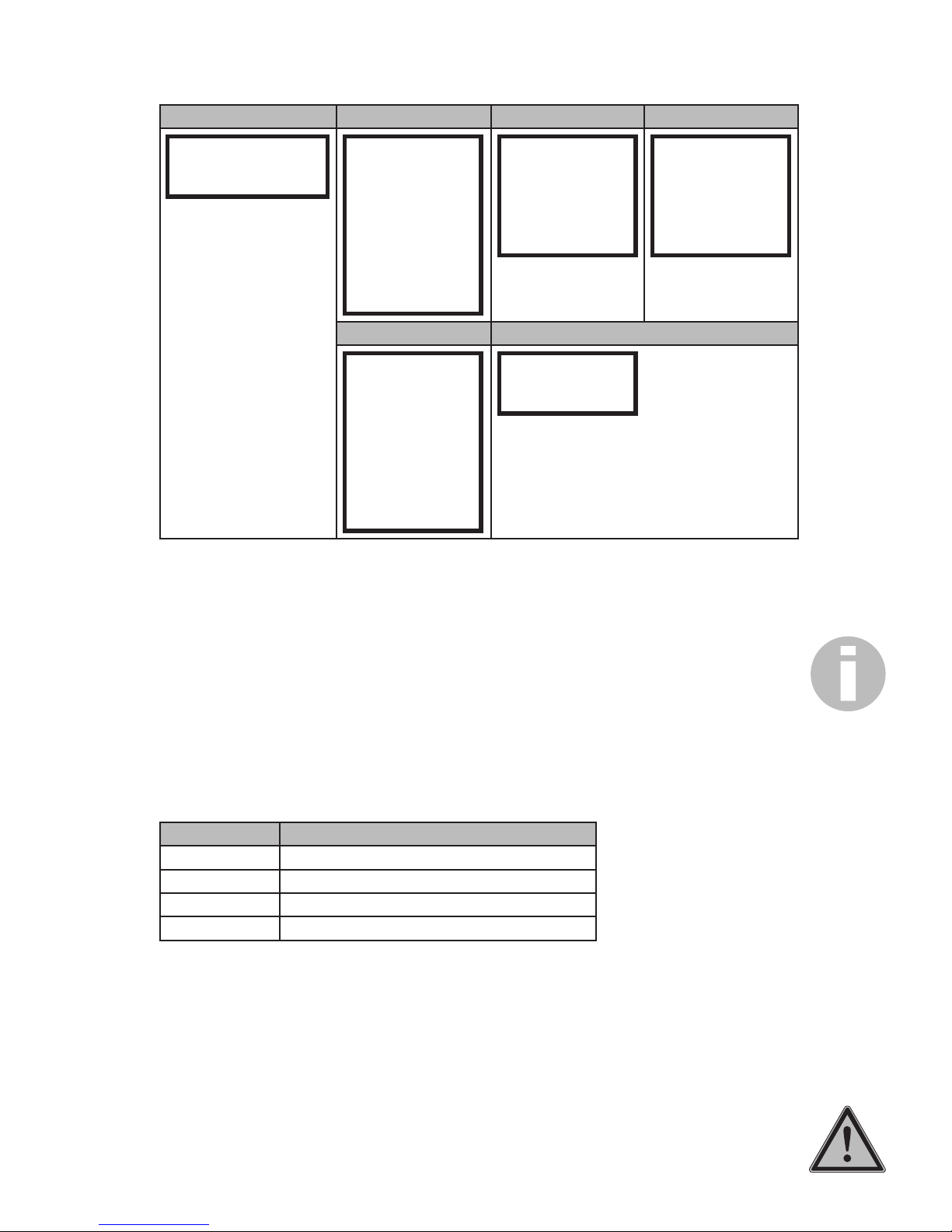
6.3 Wiring diagram
- + + -
1 2 3 4 5 6 7 8 11 12 13 14 15 16 17 18 19 20 21 22
23 24 25 26 27 28 29
1. Sens. 2. Sens. 0/4 ... 20
mA Rel. 1 Rel.2 Rel.3 L N PE
RS 485
Dig.
IN
A
yalpsiD
+ -
10
9
24 V DC
Terminal Connection Note
1 Sensor 1 Shielding
2 green (GN) Measuring electrode
3 brown (BN) Reference electrode
4 white (WH) Counter electrode
5 GND Ground
6 Sensor 2 Shielding
7 green (GN) Measuring electrode
8 brown (BN) Reference electrode
9 white (WH) Counter electrode
10 GND Ground
Display Display contrast Trimmer for adapting the display contrast
11 Analogue output + 0/4 … 20 mA, max. working resistance 500 Ω
12 -
14 / 15 Relay 1 Make contact (N.O.), configurable
16 / 17 Relay 2
18 / 19 Relay 3 (Alarm)
20 … 22 Power supply
23 RS 485 (option) A (-) Interface
24 B (+)
A Jumper plugged = load resistor activated
26 Digital input + Potential-free
27 -
28 24 V DC Output for switch
29 GND Ground
Fig. 6.1: Wiring diagram for measurement amplifier GW 702
14 | Operating Manual GW 702 | Assembly and Installation
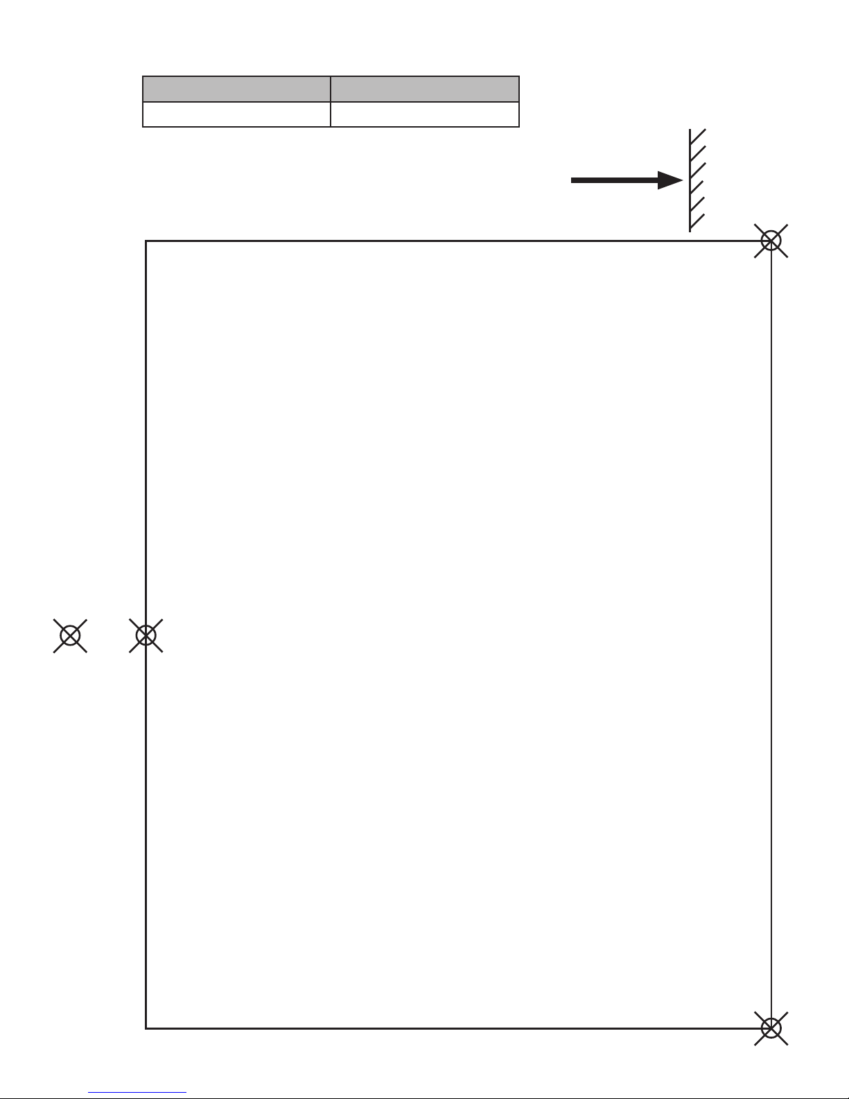
6.4 Drill template
Width x height
Measurement amplifier GW 702 151 x 120 + 15 mm

Operation | Operating Manual GW 702 | 15
7. Operation
aOrientation aid
bMeasured value sensor 1
cMeasured value sensor 2
dStatus display
eKey left ()
fKey up ()
gKey down ()
hKey right ()
i"ESC" key
After switching on, the device first indicates the measured values of sensor 1 and if applicable sensor 2. Any
possible alarm messages present are indicated in the second line.
Move in the menu with the help of the operating keys:
With the key you switch from the display of the measured value to the main menu.
With the keys and you scroll up and down.
The key is used to select a menu or a parameter.
The key is used to exit a menu and save data.
For better orientation there are various triangles visible in the display. They are intended to serve as orienta-
tion aid and specify, in which direction you can move from your respective position.
The "ESC" key brings you back to the measured value display at any time.
7.1 Setting parameters
1. When selecting a parameter the current setting is displayed.
2. Switch to the next alternative by pressing the key .
3. When you have paged through all alternatives, with a renewed press of the key the original setting
is displayed again.
Selection of alternatives
Often for a parameter you must only select between various alternatives. For this you only need the key
. With that you page from one alternative to the next, until you arrive at the starting point again or have
reached the required alternative.
With these parameters, any change becomes effective immediately. You do not need to save the setting
extra.
1. Select the parameter by pressing the key .
2. A double triangle appears behind the number and indicates, that the number can now be changed with
the keys and .
3. When you have set the required value, save your setting by pressing the key . The double triangle
disappears - the new value is saved.
Enter password
058 Code
Enter password
058 Code
Enter password
062 Code
GW 702
0.09 ppm 0.01 ppm
Sens. 1 Sens. 2
e f g h i
a b c d
16 | Operating Manual GW 702 | Operation
Setting numerical parameters
Numerical parameters can basically only be changed when a double triangle is visible behind the number.
This double triangle first becomes visible when one selects the number with the key .
Change the number with the keys and . A short key press increases or decreases the last digit by 1.
If you keep the key pressed longer, the numerical value begins to run and keeps changing until you release
the key.
Save your setting by pressing the key .
The double triangle disappears.
NOTE!
If you do not wish to save, instead of key press the "ESC" key.
7.2 Menu Overview
To switch from the measured value display to the main menu, press the key . Select menu item with key
. Start the menu with key .
Measured value display Main menu Basic settings Service
0.09 ppm 0.01 ppm
Sens. 1 Sens. 2
Preselect M1
Preselect M2
Enter password
Sensor test
Basic settings
Service
Sensor 1
Sensor 2
Analogue output
Language
No. of RS 485
Select Alarm
Product Info
Analogue Inputs
Relay Test
Erase Settings
• In the main menu you will find all functions that are used regularly.
• The menu Basic Settings contains the parameters that are set during start-up.
• In the menu Service you will find all functions for service and maintenance.
7.3. Code
Before you can undertake any settings, you must first enter the corresponding password code:
Measured value display Main menu Enter password
Code Access to the parameters in the menus
11 Preselect M1, Preselect M2, Sensor Test
86 Basic Settings, Service
others no access
7.4 Language
There are various languages available for the device. Code 86 is required for the setting.
Measured value display Main menu Basic Settings Language
Presently the languages German, English, French and Spanish are installed.
Configuration | Operating Manual GW 702 | 17
8. Configuration
Measured value display Main menu Preselect M1 / M2 Sensor Info
0.09 ppm 0.01 ppm
Sens. 1 Sens. 2
Preselect M1
Preselect M2
Enter password
Sensor test
Basic settings
Service
Sensor Info
Limit value 1
Limit value 2
Turn-on delay
Sensor slope
nA/ppm
Basic settings Sensor 1 / 2
Sensor 1
Sensor 2
Analogue output
Language
No. of RS 485
Select Alarm
Sensors
---------
The GW 702 can be operated with two sensors. When delivered the devices are preset to one or two
sensors. If you subsequently connect a second sensor, you must then activate Sensor 2 in the menu Basic
Settings.
IMPORTANT!
The gas sensors do not need to be calibrated. For the adaptation the slope is printed on the housing of
every sensor. This value is to be set in the main menu.
The function of the sensor is controlled automatically and electronically at specified intervals. In addition a
sensor test can be triggered manually at any time.
8.1 Sensors
Selection options for Sensor 1 and Sensor 2:
Selection Sensor for measuring gas
------ No sensor connected
Chlorine Chlorine gas (Cl2)
Chlorine dioxide Chlorine dioxide (ClO2)
Ozone Ozone (O3)
1. In the menu Basic Settings, select the menu item "Sensor 1". The current sensor type for Sensor 1 is
displayed.
2. Switch to the next alternative by pressing the key . Press the key until you have found the required
sensor type.
3. Exit the menu item with the key or ESC.
To set up Sensor 2 proceed as for Sensor 1.
NOTE!
The menu items "Preselect M2" and "Sensor 2" only appear with Sensor 2 activated. The measured value
display adapts likewise.
18 | Operating Manual GW 702 | Configuration
8.2 Sensor Slope
Every sensor element has the sensor slope printed on the label at works. This is to be adapted in the main
menu.
1. In the main menu, select the menu item "Preselect M1".
2. Select the menu item "Sensor Info". The current slope of the sensor is displayed.
3. Press the key and set the value specified on the sensor element with the help of the keys and
. Confirm with the key .
To set up Sensor 2 proceed as for Sensor 1.
8.3 Sensor Test
Measured value display Main menu Sensor test
0.09 ppm 0.01 ppm
Sens. 1 Sens. 2
Preselect M1
Preselect M2
Enter password
Sensor test
Basic settings
Service
Test Interval
h
Basic settings Select Alarm Alarm Sens.Test
Sensor 1
Sensor 2
Analogue output
Language
No. of RS 485
Select Alarm
Alarm Sens.Test
Value 1 Sens. 1
Value 2 Sens. 1
Value 1 Sens. 2
Value 2 Sens. 2
Direction
Alarm Sens.Test
On
Automatic Sensor Test
The device automatically checks electronically the signal of the sensor. The time interval between two suc-
cessive tests can be specified in hours in the main menu under "Sensor Test".
All switching functions of the sensor are disabled during the approx. 5 sec. test. In the display the message
"Sensor Test" is displayed. If a sensor is electrically faulty or not connected, the error message "Fault Sen-
sor 1" or "Fault Sensor 2" appears.
If you have activated the Alarm Sensor Test in the Basic Settings under "Select Alarm", the alarm relay, relay
3, also switches if the test is unsuccessful.
NOTE!
With a setting of zero hours, "0 h", the function is deactivated.
Manual Sensor Test
In addition a sensor test can be triggered manually at any time.
1. If the device is not in the measured value display, press the key "ESC".
2. Press the key .
3. Press the key to start the sensor test.
NOTE!
The sensor test is not accessible if an alarm is present.

Operating Modes | Operating Manual GW 702 | 19
9. Operating Modes
Operating states of the measurement amplifier GW 702.
Power-up phase
The connected sensor can deliver undefined values to the measurement amplifier GWZ 702 directly after
the system has powered up. This situation can lead to false alarms. All alarm messages are therefore
blocked for approx. 20 seconds after power-up or after a voltage interruption with a start delay.
Data logging
The data logging of the measurement amplifier GW 702 takes place automatically. The status is not indi-
cated in the display. The measured values of the sensors are visible over the menu Service (see section 13).
Sensor test
The device automatically checks electronically the signal of the sensor. The time interval between two suc-
cessive tests can be specified in hours in the main menu under "Sensor Test". (see section 8.3)
Alarm
Two alarm thresholds can be set, Limit Value 1 and Limit Value 2. When the alarm thresholds are exceeded,
instead of the measured value display the display indicates "Erase Alarm, press key ".
With key the alarm is acknowledged manually and the relay is switched.

20 | Operating Manual GW 702 | Relays
10. Relays
With three relays external devices can be controlled or information can be forwarded.
• Two limit values / alarm thresholds can be set per sensor.
• On reaching limit value 1, of sensor 1 or sensor 2, relay 1 is switched. This is not self-locking and
returns when the level falls below limit 1 again.
• On reaching limit value 2, of sensor 1 or sensor 2, relay 2 is switched. This is self-locking and does not
return when the level falls below limit 2 again.
• Relay 3 (Alarm) can be assigned to all four limit values at the same time: Limit value 1 and 2 of sensor
1 and of sensor 2. In the standard setting the limit values 2 of sensor 1 and sensor 2 are switched on.
The limits are pre-set depending on the model, see table 8.1.
NOTE!
CODE 86 is necessary for changes to the parameters and settings.
Limit Value Chlorine gas Chlorine dioxide Ozone
1 2 ppm 0.2 ppm 0.2 ppm
2 9.5 ppm 1 ppm 1 ppm
Tab. 10.1: Preset limit values for each measuring gas
Relay Limit value Delay time Self-
locking
Acknowledgement Use
Relay 1 1 No delay No Can be manually acknowl-
edged immediately
Optical signal generator
Relay 2 2 Yes Can be acknowledged
immediately externally via
digital input.
Can only be acknowledged
manually when the level falls
below limit 2.
Sprinkler with acknowl-
edgement via door
contact.
Relay 3
"Alarm"
-, 1 or 2
(Standard: 2)
No Can be manually acknowl-
edged immediately
Acoustic signal
generator
Tab. 10.2: GW 702 measurement amplifier relays
Example
If relay 2 activates the sprinkler, and a door contact is connected to the digital input, then in case of alarm
the sprinkler will be switched off as soon as the maintenance personnel enters the room. The display shows
“Door Contact”. If limit value 2 is still exceeded when the door is closed, relay 2 switches again.
10.1 Action in the event of an alarm or fault
Limit value 1
When limit value 1 is exceeded there is a minimum gas concentration present. Appropriate action must be
taken immediately.
CAUTION!
Repair work may only be started when the concentration has dropped below limit value 1.
Limit value 2
When limit value 1 is exceeded the endangered area and all surrounding rooms must be evacuated. The
actions listed in the health and safety regulations and chlorine alarm plans must be taken. If a limit value is
exceeded, the message "Limit value exceeded" appears in the display.
Table of contents


